Holiday Lights

For this project, I used yellow, red, and green lights that would turn on to their designated colored switches, and programmed them all to blink in a coordinated pattern with each other. Mostly, when making this project, I just kept thinking about Christmas. And while I couldn’t have snow or presents, I could at least program a tiny version of Christmas lights, while listening to carols during the project for a partial effect.

Apart from the finickiness of the switches and getting the wires to line up on the breadboard, the project was relatively easy to execute.

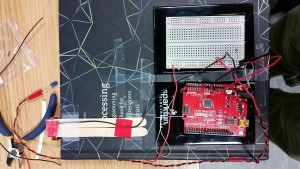
Initially, I tried to remember everything we learned from Wednesday’s class on programming and switches using photos I took from the class. Once I figured out how to turn on one yellow light with three switches, it became smooth sailing from there on what my errors were and how to fix them.

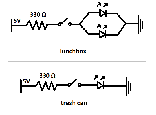
For this project, I used two red, two green, and two yellow lights, and the pairs were wired in parallel with each other so that they’d both turn on to the same switch input.

When you press the green button, the two green lights will light up at a specific pattern shown below in my coding. Likewise, when pressing the red button, the red lights would light up at a slightly faster speed, to light up whenever the green lights were off. And finally, when pressing the yellow button, the yellow lights will turn on when the other two lights are off. When pressing all three switches, the lights essentially light up in the sequence: green, then red, then yellow.

In order to make the lights work in parallel, the long ends are stuck in the same pin hole, and the short ends are put in the same row as 330 ohm resistors connected to ground. The switches are connected to the ground with a wire, and then a 10K ohmm resister in the row connected to the RedBoard.

When programming, I basically had three sections, with each switch connected to the designated color lights. Below is the chart I used to identify which switch went to which pin since it got confusing after a while with the wiring.

Switch in pin 3 turns on pin 7 green lights
Switch in pin 5 turns on pin 6 red lights
Switch in pin 4 turns on pin 2 yellow lights

Below is a video of how it works, and a copy of my coding:

CODING:

void setup() {
// put your setup code here, to run once:
//SWITCH Green
pinMode(3,INPUT);
// SWITCH Yellow
pinMode(4,INPUT);
// SWITCH Red
pinMode(5,INPUT);
//Red
pinMode(6,OUTPUT);
//Green
pinMode(7,OUTPUT);
//Yellow
pinMode(2,OUTPUT);

}
void loop() {
// put your main code here, to run repeatedly:

if(digitalRead(3) == HIGH){
digitalWrite(7,HIGH);
delay(250);
digitalWrite(7,LOW);
delay(750);
} else {
digitalWrite(7,LOW);

}

if(digitalRead(5) == HIGH){
digitalWrite(6, HIGH);
delay(100);
digitalWrite(6,LOW);
delay(500);
} else {
digitalWrite(6, LOW);
}

if(digitalRead(4) == HIGH){
digitalWrite(2,HIGH);
delay(50);
digitalWrite(2,LOW);
delay(250);
}else{
digitalWrite(2,LOW);
}
}

Please close the door behind you

My roommate is a very considerate person, yet he has a habit of leaving our room door open when he goes to the common room. To be frank, I don’t mind open doors in the daytime. But since I am a light sleeper and get awaken by the slightest rise in light or sound intensity, my roommate’s trips to the common area in the nighttime disrupt my sleep. This is why my first class assignment for Intro to IM features a switch that turns on the LED when the door gets open.

Continue reading “Please close the door behind you”

Status Indicator

This week, I made a combination of multiple switches and LED lights into a status indicator. The basic idea is to tell the user if they have successfully pressed a button by looking at the blinking lights. I got inspired to create this device while I was playing a game called Limbo. In Limbo, our protagonist is allowed to do three kinds of moves: forward move, backward move, and jump. Since I was playing on iPad, a touchscreen device, I had to move my fingers rightward, leftward or upward to make the moves. Sometimes, I failed to jump over a barrier because I swept across the screen so softly that the screen did not detect my finger movement. I wish there were signals telling me that I did not trigger the jump move. I thought that a physical button would be much easier to control than to sweep across the screen. Therefore, I created this device to tell the users if they have successfully pressed the button by the status of the LED lights.  Continue reading “Status Indicator”

Games!

Disclaimer: things in bold are little nuggets of knowledge that might come in useful. And notes to self, so I don’t make dumb mistakes again.

I love videogames. And colorful blinking lights, obviously. Given that I can’t make a full-blown videogame just yet, I decided to start with something simpler (but challenging given that this is just my second project). The goal: build and program a memory game (Simon).

Step 1 was making the LEDs actually turn on. Four buttons acted as inputs, and the LEDs were connected as four outputs. I could have as well made the LEDs turn on via the physical switches, but that would have defeated the purpose of the asignment. Nothing too different from what we did in class. It was simple enough to code, but it didn’t work out at the first go. My brain forgot to plug the outputs to ground (way to go – brain-five!). You can see the result here: https://youtu.be/yzMvNNp7sp4

And then the fun part started. Continue reading “Games!”

Cheers!

20150904_143206

With the task of turning on LED lights without physically pushing the switch with my finger, I chose to extend out the two wires that connect the two LED lights. When the two ends of the wires touch, both of the LEDs light up, like seen in the picture above.

I applied this very simple concept to the act of “cheering” of two people bumping their glasses together. I connected the two ends of the wires to conductive tape and covered two plastic cups with it. Thus electricity flows all around the surface of the two cups and when the tow cups are in contact, the two LEDs light up.

20150904_165820

One challenge I faced was figuring out how to connect the LEDs in parallel so that they light up brighter than they do when they are connected in serial.  I haven’t been able to figure out how to do so, thus the lights are half as bright as it could be when they are connected in parallel.

Little bit interactive drum


20150906_220238

You might not understand what I made (oh but look at the title of this post!) from the video and the photo, but that’s because it’s a model of the real product. So imagine the pen is a wood stick and the copper sheet is the main body of a drum, there we have a little bit interactive drum that lights up when a player beats the drum!

Alright, thank you for watching and/or reading.

Tableware–Chopsticks and Spoon

IMG_0001 IMG_0002

My circuit which I only added chopsticks and a spoon into is quite simple. To make the light on, we only need to make sure that the voltage assigned to the light will be around its rated voltage. In addition, having a loop is quite important.

We can’t use common switch, so we’ll try something new. At first, I was going to find something which is made of metal that can conduct electricity. Then I chose my necklace and used it as conductor in my circuit, however, the light was still off and it didn’t work at all. Maybe the necklace has a quite large resistance, which leads to the light does not have enough voltage to be on. Or the necklace’s material does not have a good conductive in the circuit.

The second time, I chose nail clippers. When I cut it, I thought the top of the nail clippers can be closed to form a loop, maybe it can be a part of my circuits. Nevertheless, the light will always be on when I use the nail clippers as a connection.

The third time, I had a very simple idea by using chopsticks and spoon. Luckily, they naturally became a close circuit with GREAT conductive ability.


Recycle!

So as to be caring, environmentally friendly citizens, my roommates and I have agreed to use a seperate trash bin for plastic. However, banana peels and remnants of humus kept landing in the recycling bin, despite my persistance in placing the ‘Plastic’ label back on it again and again. As the label proved to be an inefficient solution, I thought a warning light could solve the problem.

Although I was aiming for a light that goes up each time someone opens the trash can, I started out with a smaller project, a lunchbox. First, I fixed two small pieces of conductive fabric to the ends of two longer wires with conductive tape (so that each wire had one end with the fabric on it, and one end ‘open’). Then the conductive fabric parts were fixed to the back of the lunchbox so that they would touch when the box is opened (see video).

Happy that my idea works, I made two longer wires with conductive fabric at their ends and I soldered two long wires to the two ends of a LED for my trash bin. Having disassambled the bin, I fixed one of the fabric pieces on its bottom, and the other one at the end of the pedal (in a way that they would touch when the pedal is stepped upon).


The sound of the following footage is a happy accident, and not part of my work (unfortunately).

See the two circuits in the picture below.

im

Books!


I love reading, so the first thing that came to mind for the assignment was (naturally, of course) a booklamp! Nobody wants to use their filthy hands to press a darn button and turn on a lamp, so why not make it turn on automatically when you open the book? Voilà, the next great invention of the XXI Century. Thank me later, I’m busy getting my speech ready for when I pick up my Nobel Prize.

My first attempts consisted in a simple switch: close switch, turn on LED. Simple in paper. The idea was to have the opening motion of the book push two pieces together such that they touched (and closed the circuit) on the back of the book. But not even the aid of wooden sticks, string and magnetic tape was enough to make my vision come true, as it was hard to make both pieces actually touch each other. :c

Back to the drawing board. then, I remembered a little circuit Luis made while messing around paying attention in Wednesday’s class. In essence, it acted as a NOT logic gate: closing the switch would provide a path with least resistance, reducing the current flowing through the LED and turning it off. Problem solved (thanks, Luis!)

.2015-09-03 14.56.22

I built my switch over this concept: opening the book would open the switch, turning the LED on thanks to this makeshift NOT gate. By repurposing the wooden sticks and using some copper tape, I built a little structure on top of the book that would close the circuit as long as the book remained closed. I curled up the pieces of tape into circles such that the shape’s slight spring force would keep the two sides of the switch in contact. The rest is just regular wiring and a resistor.

2015-09-03 14.50.00

And this is the end result (at the bottom, because I can’t move videos around :c). Yay! 😀