Inside Your Mind – Interactive Fluid Typography Experience and User Testing

As I was experimenting with m project, I built Inside Your Mind – a second-person psychological narrative experience created in p5.js. I felt like with the creativity I developed in the class Tinkercad would not be enough to show my ideas, altough I tried to make a project on Tinkercad I did not open fully with it, so I chose to do my interactive experinec in p5. The project moves away from game mechanics and goals, and toward something more expressive and open-ended: a guided journey through four emotional stages of the mind, rendered through fluid particle typography and sound.

The experience opens with a kinetic typography intro sequence a personal greeting, a typewriter reveal, a search bar that types “inside your mind” — before transitioning into the main particle world. From there, users navigate different stages of mind, noise, overthink, break and finally silence.

User Testing

User testing was conducted with participant who experienced the full interactive sequence from the intro through all four stages. My little brother.  Participant were observed interacting freely with no instructions given beyond “explore it.”

The response was overwhelmingly positive.

Tester consistently described the experience as something they hadn’t encountered before, not a game, not a website, something in between that felt genuinely immersive. My brother spent more time in the experience than expected, going back and forth between stages to compare how the particles moved differently in each one. The fluid typography was the element that resonated most strongly. Tester were drawn to how the text was simultaneously readable and alive. The sound design was a notable highlight. Tester immediately noticed that each stage sounded different, and several remarked that the cursor sounds made the experience feel tactile, like they were touching something. The wind sound in Stage 1, the water drops in Stage 2, the glitch crackle in Stage 3, and the bell chimes in Stage 4 each reinforced the emotional tone of that chapter which made it more cohesive.

Link to user testing video: https://drive.google.com/file/d/1y8koBlJ7WqWSgiGLDeGFhjZYJn5P-0Ib/view?usp=drivesdk

Areas noted for potential refinement:

I am considering to add an introduction to the experience explaining more about the interactivness, I am inspired by motion design, lately have been watching different motion design ad proposals for brands and I enjoyed the animations, so I would want to implement it to my project by learning and applying it.

Final Project: Flame Keeper

Flame Keeper is a browser-based game controlled by a physical Arduino. A potentiometer and a push button are the only inputs. There is no keyboard, no mouse, no touchscreen. Your hands are on hardware, and what happens on screen responds directly to what you do with them.

The goal is simple: keep a candle flame alive as long as possible. The flame slowly dies if you neglect it and gets destroyed quickly when wind gusts hit. Your job is to manage both threats at the same time using two very different physical actions.

Demo Video

Concept

A candle flame is fragile. It responds to the air around it, flickers under pressure, and goes out if conditions get bad enough. I wanted to recreate that fragility as a game mechanic where the player feels like they are genuinely tending to something.

The project is meant for anyone who picks it up with no instructions. The two inputs are immediately physical and tactile. Turning a knob and pressing a button are things people already know how to do. The challenge is learning what those actions mean on screen, and then staying coordinated under pressure.

It is a single-player survival game. There is no finish line. You survive as long as you can and your best time is saved so you can try to beat it.

How It Works

The system has two parts: an Arduino that reads sensors and sends data, and a p5.js sketch running in the browser that receives that data and runs the game.

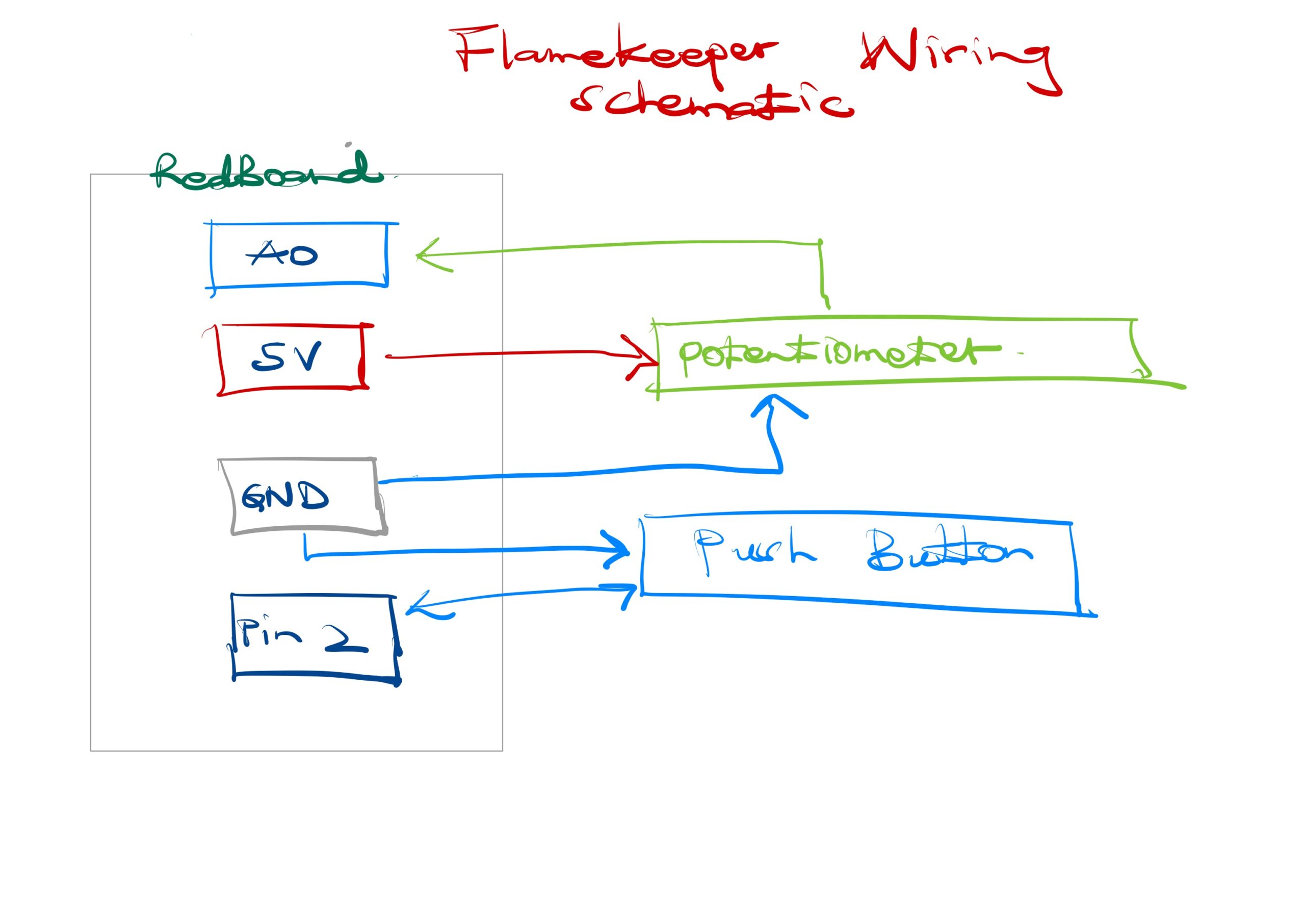
The Arduino reads a potentiometer on pin A0 and a push button on pin 2. Every 30 milliseconds it sends the potentiometer value as POT:value over serial. When the button is pressed or released it sends PRESS or RELEASE. The browser connects to the Arduino using the Web Serial API, available in Chrome and Edge. No app or driver is needed beyond a USB cable.

Inside the game, the potentiometer value maps to a cursor on a horizontal bar. A green zone moves slowly back and forth across that bar. If the cursor is inside the green zone, the flame heals. If it drifts out, the flame slowly loses health. Every 2 to 4 seconds a wind gust arrives. During a gust the flame loses health rapidly unless the player holds the button. Holding the button raises a shield that blocks all gust damage. Difficulty increases over time as gusts come more frequently.

Interaction Design

The two inputs are intentionally asymmetric. The potentiometer requires continuous attention and fine motor control. The button requires a fast reaction to a visual cue. During a gust the player must do both at once, which is where the tension of the game lives.

Feedback is layered so the player always knows what is happening without reading text. The flame shrinks visually as health drops. The screen edges pulse red when damage is being taken. Wind lines fly across the screen during gusts. Animated rings appear around the flame when the shield is active. A status pill at the top of the screen confirms the current threat and whether the shield is up.

The start screen shows both controls and what they do before the game begins, so no explanation from me is needed. The game over screen shows the player’s score and their all-time best, which gives a reason to replay.

Arduino Source Code

Full source code is on GitHub: github.com/EnockMagara/IM_FINAL

const int BUTTON_PIN = 2;
const int POT_PIN    = A0;

bool wasPressed = false;

void setup() {
  pinMode(BUTTON_PIN, INPUT_PULLUP);
  Serial.begin(9600);
}

void loop() {
  bool pressed = (digitalRead(BUTTON_PIN) == LOW);

  if (pressed && !wasPressed)  Serial.println("PRESS");
  if (!pressed && wasPressed)  Serial.println("RELEASE");
  wasPressed = pressed;

  Serial.print("POT:");
  Serial.println(analogRead(POT_PIN));

  delay(30);
}

Wiring Schematic


How This Was Made

The game runs entirely in the browser using p5.js 1.9.3 and the p5.sound addon, both loaded from CDN. The Web Serial API handles communication between the browser and the Arduino with no additional libraries.

The flame is drawn each frame using layered ellipses with positions driven by Perlin noise, which gives it organic flickering motion. The glow effect is a series of concentric ellipses drawn from the outside in with decreasing opacity. The shield uses sine-wave-animated rings. All color is in HSB mode so hue shifts naturally as flame health changes from red to amber to gold.

The sweet spot bar maps the raw potentiometer value (0 to 1023) to a pixel position on screen. The green zone has a target position that slowly lerps toward a new random target every four seconds, creating the moving challenge.

Audio uses two p5.Oscillator instances. A sine wave plays as an ambient hum tied to flame health. A sawtooth wave plays during gusts. Both are initialized on the first user click to satisfy browser autoplay policy.

Best score is stored in localStorage so it persists across page reloads without a server.

Libraries used: p5.js, p5.sound. Fonts: Cinzel and Cinzel Decorative from Google Fonts. Web Serial API documentation from MDN. AI (GitHub Copilot) was used throughout development for debugging serial communication, structuring the game loop, and designing the UI layer.

What I Am Proud Of

The physical-to-digital mapping feels genuinely tight. When you turn the potentiometer, the cursor on screen moves exactly as fast as your hand does. There is no noticeable lag. That responsiveness is what makes the interaction feel real rather than simulated.

I am also proud of how the difficulty curve works without any explicit levels. The gust interval shrinks by five frames every time you survive a gust, so the game gets harder the longer you last without me having to design separate stages.

The start screen and the game-over card both came together better than I expected. Having the controls explained before the game starts removed the need for me to stand next to it and explain anything, which was the main lesson from user testing.

Areas for Future Improvement

The potentiometer-to-cursor mapping is linear, which means the sweet spot is equally difficult everywhere on the bar. A nonlinear mapping that makes the center zone slightly easier and the edges harder would create more interesting tension.

I would add a second visual reading of flame health beyond the bar. Right now the flame shrinks as health drops, but that change is subtle. A visible glow radius that shrinks more dramatically would communicate danger faster.

The button currently has one function: shield during gusts. A second mechanic tied to a short button tap versus a long hold would add depth without adding more hardware.

The game has no sound design beyond two oscillators. Real flame crackling and wind sound effects would make the experience significantly more immersive.

Reflection

The biggest thing I learned is that physical input is unforgiving in a way that keyboard input is not. A keyboard always registers. A breadboard button that is rotated 90 degrees reads as permanently pressed and the game never starts. Debugging hardware and debugging software at the same time is a different skill from debugging software alone.

User testing taught me that what is obvious to the maker is not obvious to the user. I knew what the sweet spot bar meant because I built it. My tester had never seen it before. Adding one line of explanatory text on the start screen solved the confusion completely. It cost almost nothing to add and made the project function without me in the room.

If I had two more weeks I would add a two-player mode where one person controls the potentiometer and the other controls the button, forcing coordination between two people instead of one person managing both inputs alone.

Week 14 – Final Project! – Megan

Music Producer — Final Project

“Music gives a soul to the universe, wings to the mind, flight to the imagination, and life to everything.” — Plato

Concept

I truly love music. I actually realized, while looking at my past projects, that I have implemented music in many of then as a core element. I think it’s maybe because of my surroundings and how I grew up playing so many instruments, and for my final project, I wanted others to feel this unique connection to music too. I wanted to give a space for users to experiment with sound and visuals so that they would want to create music, which is very different than only listening to it. So, that is how my project was born.

“The only way to do great work is to love what you do.” — Steve Jobs

In general, I wanted to build something that actually feels like a creative tool and not just a demo. The idea is that you are a music producer. You start by recording your own voice, and then you build a whole song on top of it using different instruments like piano, drums, and bass, all controlled through physical buttons connected to an Arduino. Everything you play gets layered and looped, and at the same time the system generates a live visual artwork based on what you are creating.

I wanted to make something where every single action has a visual response, so that by the end you do not just have a song, you have something that looks like a living piece of art. The kind of thing where even if you have no idea how to make music, you can still produce something that feels like yours.

It is designed for anyone who wants to experiment with sound and visuals in a fun and intuitive way. The controls are simple enough that you do not need to be a musician, but expressive enough that if you are, you can actually do something interesting with it.

How It Works

Interaction Design

The whole experience is split into three modes: Piano, Drums, and Bass. In each mode, the four Arduino buttons trigger different sounds, piano notes, drum hits, or bass notes. The potentiometer controls the playback speed of any loops you have selected. A green LED on the Arduino lights up when you are recording and goes red when you stop.

On the screen you have a recordings panel that you can toggle open and close, recording buttons, and mode selectors. The center of the screen always shows a Siri-like wave visualization that responds to everything playing. And depending on which mode you are in, a different kind of art generates in the background as you play. Subtle drifting lines for piano, glowing expanding circles for drums, and thickening colored waves for bass.

The flow is: record your voice, pick a mode, play sounds on top, record the whole thing as a loop, loop it, and keep building on top of that.

Arduino

The Arduino does only one thing and that is reading the physical inputs and sending them to p5.js. It does not make any decisions about what the sounds mean. It sends the state of all four buttons and the potentiometer value every 50 milliseconds, formatted as b1,b2,b3,b4,pot. It also listens for messages back from p5 to control the LEDs. LED:1 turns the green on and LED:0 goes back to red.

I kept the Arduino side as clean and minimal as possible on purpose. So that the user gets that p5.js is the brain and Arduino is just the hands.

You can find the full Arduino source code here

p5.js

The sketch handles literally everything else: the audio system, the visuals, the UI, the serial communication, and the art generation. It has multiple screens (menu, instructions, main), a full recording and playback system using p5.SoundRecorder and p5.SoundFile, an FFT analyzer for the wave visualization, a particle system for the art, and a styled HTML button system injected directly from JavaScript.

You can also see the full p5.js source code here

How This Was Made

The starting point for the audio visualization was the Sound Visualization: Frequency Analysis with FFT video by Daniel Shiffman on The Coding Train. I had never used p5.FFT before and that video really broke it down in a way I could actually follow. From there I understood how fft.waveform() gives you the time domain signal and fft.getEnergy() gives you the overall loudness, which is exactly what I needed to make the wave lines spread based on how loud the audio is. I spent a lot of time with that one and went back to it probably like four or five times throughout the project.

For understanding how p5.SoundRecorder and p5.SoundFile worked together I went back to The Coding Train’s p5.Sound library series starting from episode 11.1. The documentation alone was not enough for me, I needed to see it in action to understand the difference between what the recorder does versus what the SoundFile stores and when it is actually ready to use.

For the HTML buttons inside p5, like styling them with CSS classes and using createButton() and addClass(), I found The Coding Train’s p5.js DOM tutorials really useful. I did not know you could inject a style tag directly from JavaScript in setup and have it affect your buttons in real time. That one I kind of figured out by going through the p5.js reference library and experimenting a lot, but the DOM series gave me the foundation to even know that was possible.

For the particle system, the piano lines, the drum circles, I referenced The Coding Train’s Nature of Code series on particle systems for how to structure a particle with a life, a decay, and properties that change over time. I had seen it before but applying it here in a way that felt musical and not just random took a lot of trial and error honestly.

For the serial communication between Arduino and p5.js I followed what we learned in class.

I also used ChatGPT AI, mainly for debugging. A big portion of the time I spent on this project was debugging, and having something I could explain the problem to and get a clear answer helped a lot. I always made sure I understood what it was suggesting before implementing it, because if I did not understand it I could not fix the next thing that broke on top of it.

What I’m Proud Of

The Mode System

The thing I am most proud of conceptually is how the same four buttons completely change meaning depending on which mode you are in. In piano mode they are notes, in drums mode they are different drum hits, in bass mode they are bass lines. And all of that switches with one click, no lag, no confusion. Building that felt simple in theory but getting the visual art to also switch correctly, and making sure the wave visualization responded differently in bass mode, that took a lot of coordination between different parts of the code. This is the core of the whole interaction design and I think it works really well.

The Recordings Panel

The recordings panel was one of the more technically satisfying things I built. It is a slide-in panel inside the canvas, not a separate screen, where you can see all your recordings, click to play or stop them, double click to rename them, and delete selected ones. What makes it tricky is that all the interaction has to be calculated manually because it is drawn on the canvas and not a real HTML element. So I had to make sure the coordinates in drawRecordingsPanel() matched exactly with the hit detection in mousePressed(), otherwise clicking a recording would trigger the wrong one or nothing at all.

// y has to match exactly between drawing and clicking
let y = 196 + i * 46;
if (mouseX < 252 && mouseY > y - 14 && mouseY < y + 24) {

Also managing the selectedRecordings array, tracking which ones are playing, and deleting them in descending order so the indexes do not shift mid-loop, that took me more debugging than I expected and I was very happy when it finally worked correctly.

The Voice Wave

The wave visualization is honestly the thing I am most proud of technically. The idea is that all 9 lines overlap in the center when it is quiet and spread apart as the audio gets louder. I had to figure out a math system where each line gets a t value from -1 to 1, and the amplitude of that line is abs(t) times baseAmp, so the outermost lines spread the most and the center line never moves. Then I flip the direction for the top half versus the bottom half so they mirror each other like a reflection.

let t   = map(k, 0, N - 1, -1, 1);
let amp = abs(t) * baseAmp;
let dir = t >= 0 ? 1 : -1;
And in bass mode the lines that belong to the note you are pressing get thicker using lerp() so the thickness transitions smoothly instead of snapping. Getting that to feel right took a lot of tweaking. At first it looked too dramatic, then too subtle. I think where I landed feels good because it is noticeable without being distracting.

The Art Per Mode

Making every sound trigger a different visual response was something I really cared about from the beginning. For piano it is thin drifting lines that appear across the screen and slowly fade. For drums the circles are sized by drum type, the kick spawns big glowing circles and the hihat spawns tiny ones. For bass the wave lines thicken in the color that belongs to the note you are pressing. None of it is random in a meaningless way, every parameter was chosen to match the feeling of that sound. That intentionality is something I am really proud of.

Areas for Future Improvement

Honestly one of the biggest things missing right now is the ability to export your final song as an audio file. You can loop everything and listen to it but there is no way to actually save what you made and share it with someone, which feels like a pretty big missing piece for a tool that is supposed to be about music production.

I would also love to add volume control per recording. Right now all selected recordings play at the same level, which means if you stack too many loops it gets muddy and hard to hear what is what. Being able to raise or lower individual loops would make it way more usable as an actual production tool.

The piano art could also be a lot more interesting. Right now the lines just drift horizontally and fade, but I wanted them to feel more like a magic keyboard that reacts specifically to which note you are pressing, not just that a note was pressed. I did not get there in time.

And if I had another two weeks I would probably add some kind of BPM sync so that the loops actually stay in time with each other instead of playing freely. Right now if you start two recordings at slightly different moments they drift out of sync pretty fast, which limits how musical the final result can actually be.

Overall I am really proud of this project. It is the most complex thing I have built so far and it actually works the way I imagined it when I first wrote down the concept. That does not always happen so it feels good when it does.

SCHEMATIC

IMAGES

VIDEO DEMO

Final Project: MindFlash

Concept

My final project was is a memory-based reaction built with Ardruino. The game displays a growing sequence of coloured LEDs and the user is supposed to repeat the exact sequence by correctly pressing the corresponding buttons. With each successful round, the game becomes more challenging by increasing the length of the sequence by one. There are three difficulty levels of this game: easy, medium and hard. The difficulty mode determines how long the sequence is displayed for. The higher the level, the shorter the display time of the sequence. The level of the game is controlled with a potentiometer.

The motivation behind MindFlash comes from my interest in memory games and sequences. I also wanted explore how a user can recall sequential information in real time. Throughout this course, there have been a lot of readings and discussions on user feedback and making designs with users at the center of the design. This idea shaped my development of the game and I placed much emphasis on the feedback and interaction of the user such as giving each button its own distinct tone, flashing the corresponding LED on every press, and using a countdown sequence before each round. Every interaction is designed to keep the player informed and engaged.

Link to Project

MINDFLASH

Demo of Project

Implementation

Interaction design

MindFlash is designed around the principle of continuous and immediate feedback at every stage of interaction. When a player presses a button, the corresponding LED lights up and a unique tone plays simultaneously, creating a sensory confirmation that their input was registered. Each of the four buttons has its own distinct pitch, so players can begin to associate sounds with colors over time. Difficulty is controlled through a potentiometer, with three levels indicated by a bank of LEDs, giving the player a clear and persistent visual indicator of their current challenge setting. The game opens with a startup test and a countdown sequence, easing the player in rather than dropping them straight into action. A correct sequence is rewarded with an ascending two-tone chime, while wrong inputs trigger a distinctly different falling sound, making success and failure immediately distinguishable without the player needing to look away from the LEDs. The game over state further reinforces failure through a flashing all-LED pattern.

Sketch

Ardruino code

/*
  MINDFLASH GAME
  
  OUTPUTS
  2  - Green LED
  3  - Yellow LED
  4  - Red LED
  5  - Blue LED
  8  - Level LED 1
  9  - Level LED 2
  10 - Level LED 3
  12 - Piezo buzzer
  INPUTS  
  A0  - Potentiometer
  A1  - Button (S2)
  A2  - Button (S4)
  A3  - Button (S1)
  A4  - Button (S3)
*/

// PIN DEFINITIONS
const int LED_PINS[]   = {2, 3, 4, 5};       
const int BTN_PINS[]   = {A1, A2, A3, A4};   
const int LVL_LEDS[]   = {8, 9, 10};
const int BUZZ_PIN     = 12;
const int POT_PIN      = A0;
const int NUM_COLORS   = 4;
const int MAX_SEQ      = 20;

// BUTTON TONES 
const int BTN_TONES[]  = {415, 310, 250, 210};

// GAME STATE
int sequence[MAX_SEQ];
int seqLen   = 1;
int flashDur = 500;

// SOUNDS 
void beep(int freq, int dur) {
  tone(BUZZ_PIN, freq);
  delay(dur);
  noTone(BUZZ_PIN);
}
void correctSound() {
  beep(1000, 100); beep(1300, 200);
}
void wrongSound() {
  beep(330, 250);
  beep(220, 250);
  beep(147, 550);
}

// BUTTON FEEDBACK (light + sound together)
void buttonFeedback(int btnIdx) {
  tone(BUZZ_PIN, BTN_TONES[btnIdx]);   // start tone
  digitalWrite(LED_PINS[btnIdx], HIGH);
  delay(150);
  noTone(BUZZ_PIN);                    // stop tone
  digitalWrite(LED_PINS[btnIdx], LOW);
  delay(50);
}

// LIGHTS
void allLedsOff() {
  for (int i = 0; i < NUM_COLORS; i++) digitalWrite(LED_PINS[i], LOW);
}
void allLedsOn() {
  for (int i = 0; i < NUM_COLORS; i++) digitalWrite(LED_PINS[i], HIGH);
}
void flashLed(int idx, int dur) {
  tone(BUZZ_PIN, BTN_TONES[idx]);      // play tone during sequence flash too
  digitalWrite(LED_PINS[idx], HIGH);
  delay(dur);
  noTone(BUZZ_PIN);
  digitalWrite(LED_PINS[idx], LOW);
  delay(200);  
}

// READ DIFFICULTY 
void readMode() {
  int pm = analogRead(POT_PIN);
  if (pm >= 700) {
    digitalWrite(8,HIGH); digitalWrite(9,LOW);  digitalWrite(10,LOW);
    flashDur = 700;
  } else if (pm >= 350) {
    digitalWrite(8,HIGH); digitalWrite(9,HIGH); digitalWrite(10,LOW);
    flashDur = 500;
  } else {
    digitalWrite(8,HIGH); digitalWrite(9,HIGH); digitalWrite(10,HIGH);
    flashDur = 300;
  }
}

// SHOW SEQUENCE 
void showSequence() {
  delay(1000);
  for (int i = 0; i < seqLen; i++) flashLed(sequence[i], flashDur);
  delay(300);
}

// WAIT FOR ONE BUTTON PRESS
int waitForButton() {
  while (true) {
    for (int b = 0; b < NUM_COLORS; b++) {
      if (digitalRead(BTN_PINS[b]) == HIGH) {
        delay(40);                                
        while (digitalRead(BTN_PINS[b]) == HIGH); 
        return b;
      }
    }
  }
}

// GET USER INPUTS & VERIFY 
bool getUserInputs() {
  for (int i = 0; i < seqLen; i++) {
    int btn = waitForButton();
    buttonFeedback(btn);
    if (btn != sequence[i]) return false;
  }
  return true;
}

// COUNTDOWN 
void countdown() {
  for (int i = 3; i > 0; i--) {
    allLedsOn();
    beep(800 + (3 - i) * 150, 150);
    delay(700);
    allLedsOff();
    delay(200);
  }
  // GO!
  allLedsOn(); beep(1400, 200); allLedsOff();
  delay(400);
}

// GAME OVER 
void showGameOver() {
  wrongSound();
  for (int b = 0; b < 4; b++) {
    allLedsOn();  delay(300);
    allLedsOff(); delay(300);
  }
  delay(800);
}

// SETUP 
void setup() {
  Serial.begin(9600);
  for (int i = 0; i < NUM_COLORS; i++) {
    pinMode(LED_PINS[i], OUTPUT);
    pinMode(BTN_PINS[i], INPUT);   
  }
  for (int i = 0; i < 3; i++) pinMode(LVL_LEDS[i], OUTPUT);
  pinMode(BUZZ_PIN, OUTPUT);
  // startup test
  allLedsOn();
  digitalWrite(8,HIGH); digitalWrite(9,HIGH); digitalWrite(10,HIGH);
  beep(1000, 400);
  delay(600);
  allLedsOff();
  digitalWrite(8,LOW); digitalWrite(9,LOW); digitalWrite(10,LOW);
  randomSeed(analogRead(A5)); 
}

// MAIN LOOP 
void loop() {
  readMode();
  // wait for any button press to start
  bool started = false;
  for (int b = 0; b < NUM_COLORS; b++)
    if (digitalRead(BTN_PINS[b]) == HIGH) { started = true; break; }
  if (!started) return;
  // debounce the start press
  delay(50);
  while (digitalRead(BTN_PINS[0]) == HIGH ||
         digitalRead(BTN_PINS[1]) == HIGH ||
         digitalRead(BTN_PINS[2]) == HIGH ||
         digitalRead(BTN_PINS[3]) == HIGH);
  allLedsOff();
  seqLen = 1;
  readMode();
  countdown();
  while (seqLen <= MAX_SEQ) {
    sequence[seqLen - 1] = random(0, NUM_COLORS);
    Serial.print("Round "); Serial.println(seqLen);
    showSequence();
    if (getUserInputs()) {
      correctSound();
      seqLen++;
      delay(500);
    } else {
      showGameOver();
      seqLen = 1;
      break;
    }
  }
  allLedsOff();
  delay(500);
}


How It’s Made

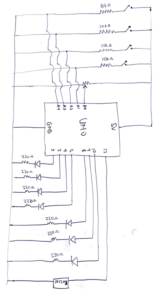
For this project, the inputs are push switches and a potentiometer. A potentiometer was connected to the 5V power source, an analog read pin and ground. The analog read pin reads the value of the potentiometer to control the level of the game. 4 push switches were connected in parallel to the 5V power source, an analog read pin and a pull down resistor of 10kΩ resistor to ground. The analog pins read the digital inputs of the push switches and that is used as the logic for matching the sequences.

The outputs of the project are a buzzer and sets of LEDs. The LEDs were connected to digital pins, a 330Ω resistor and ground. There are two sets of LEDs for this project. Set A is a set of 3 red LEDs and these LEDs indicate to the user the level of the game. The code reads the value of the potentiometer and maps it to one of the three level and this is reflected by the red LEDs. Easy mode lights up one LED, medium lights up two LEDs and hard lights up three LEDs. Set B is a set of 4 LEDs: red, yellow, blue, green. A random sequence is generate out of these colors and the user is supposed to match this using the push switches. The final output is a buzzer which is connected to a digital pin and ground. The buzzer makes sound for a countdown to start the game, makes a success sound, wrong sound and sounds specific to each color.

The pressing the push button lights up the corresponding LED bulb and makes a sound specific to that color. Chat GPT was used to generate the frequencies of sounds for the countdown, success sound, wrong and game over sound, and the sounds corresponding to each color.

Part of the project I’m proud of

The part of this project I’m particularly proud of is the code behind this project. The most difficult part of the project was writing my idea of the project into a working code and figuring it out made me very proud. The highlight of the code were the functions I made for the game.

void readMode() {
  int pm = analogRead(POT_PIN);
  if (pm >= 700) {
    digitalWrite(8,HIGH); digitalWrite(9,LOW);  digitalWrite(10,LOW);
    flashDur = 700;
  } else if (pm >= 350) {
    digitalWrite(8,HIGH); digitalWrite(9,HIGH); digitalWrite(10,LOW);
    flashDur = 500;
  } else {
    digitalWrite(8,HIGH); digitalWrite(9,HIGH); digitalWrite(10,HIGH);
    flashDur = 300;
  }
}

This is the function that controls the level of the game. The reason this is the highlight of the whole project for me is that writing this code was a breakthrough moment for me. Once I figured this part out, everything else seemed to follow and I was able to implement my ideas.

Reflection

Making this project was actually very fun. A new layer of complexity was added when implementing my ideas because as aside the code, I also had to figure out the connections of the circuits. I found myself placing LEDs at almost every point to check if the connections I had made were right in the testing phase. The LEDs were my debuggers for this project. I also played around a lot with the delay function in the project to ensure a smooth user interaction

The user testing opened me up to things I missed during my testing of the program and changed how I thought about the whole project. It made me add more feedback for the user especially being in a virtual space where a user could not physically feel a button, adding these feedbacks improved the overall project and I hope these feedbacks will be enough for a user in a virtual space.

Future improvements for this project is introducing a scoring system which is based on the time the user presses the buttons. This can expand the project from just testing memory to testing memory and reaction. The scoring system can also be used to create a leaderboard and it will be a fun game to play among friends.

Week 13: User Testing for Final Project

I had a slight change of plans for my final project, but I’ll still be using the same components (buttons and sound sensor), except for the ultrasonic distance sensor which I have swapped to use the photoresistor sensor instead. Initially, I wanted to do a Philippine-style Jeepney game, but I found that it would take too long to make the graphics and would cause for more complicated game mechanics as well as the Jeepney physical controller being more time-consuming. My new idea is a Philippine-style ice cream Sorbetes game, which is a rhythm game, similar to guitar hero. On p5.js, there will be four lanes with different colors and in the game, they’re the different ice cream flavors. The four lanes represent four different buttons on the Arduino and you have to click it when there’s that colored-circle falling down. The player earns more money (Pesos), the more they catch and they get three lives for missed ones.

USER INTERACTION VIDEO

I made my mom play the game and it was pretty clear to her as it has very simple and quite known mechanics. The game has clear functions that let you know when you catch or didn’t catch ice cream, I still do wanna add sound effects to make it better in this aspect, though. As per the Arduino, although she said that it was registering her moves well, she did find it a bit overwhelming with the wires and the buttons were too small and sometimes would disconnect from the breadboard.

The interaction between p5.js and Arduino worked really well, the buttons clicked right on time and it reflected on the p5.js. The game is quite a simple rhythm game and pretty easy to follow. However, at the time of filming, I didn’t have the photoresistor or sound sensor to test out yet. I will be adding more mechanics to make it more challenging using the two sensors. The controller is also a huge part of my project and I’m working on designing and ordered the things I’ll need for it, thanks to the stipend given. I got female-to-male jumper wires, bigger buttons, and some decorative pieces for the controller.


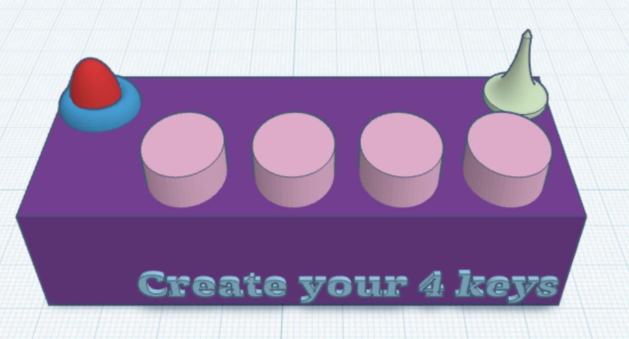
Create your 4 keys – Final project

Concept:
Create Your 4 Keys is an interactive music experience that allows participants to create their own rhythms and sound patterns using only four buttons. Each button acts like a musical key that plays a different note when pressed. The potentiometer allows the user to control and change the pitch of the sounds, making the notes lower or higher. I wanted to explore the idea of creating a simple music instrument for example Pianos usually have (from what I’ve seen) a lot of keys and sometimes it feels overwhelming, especially for people who are not musicians -like me and just want to learn!

So I started asking myself what can someone create with only four keys? Instead of focusing on every key and sound, I wanted to focus on only 4 keys for this project for experiments, rhythm, repetition, and just playing and having fun overall! Even with a limited number of buttons, the participant can still create many different patterns depending on the order, timing, and pitch of the notes they create.

The project of course is designed for anyone, even people with no musical background, because the interaction is meant to feel fun. Once the participant presses a button, the system responds instantly with sound which shows the action and feedback. The potentiometer also shows the interaction because it changes how the notes sound in real time, participants can change it and make it sound different.

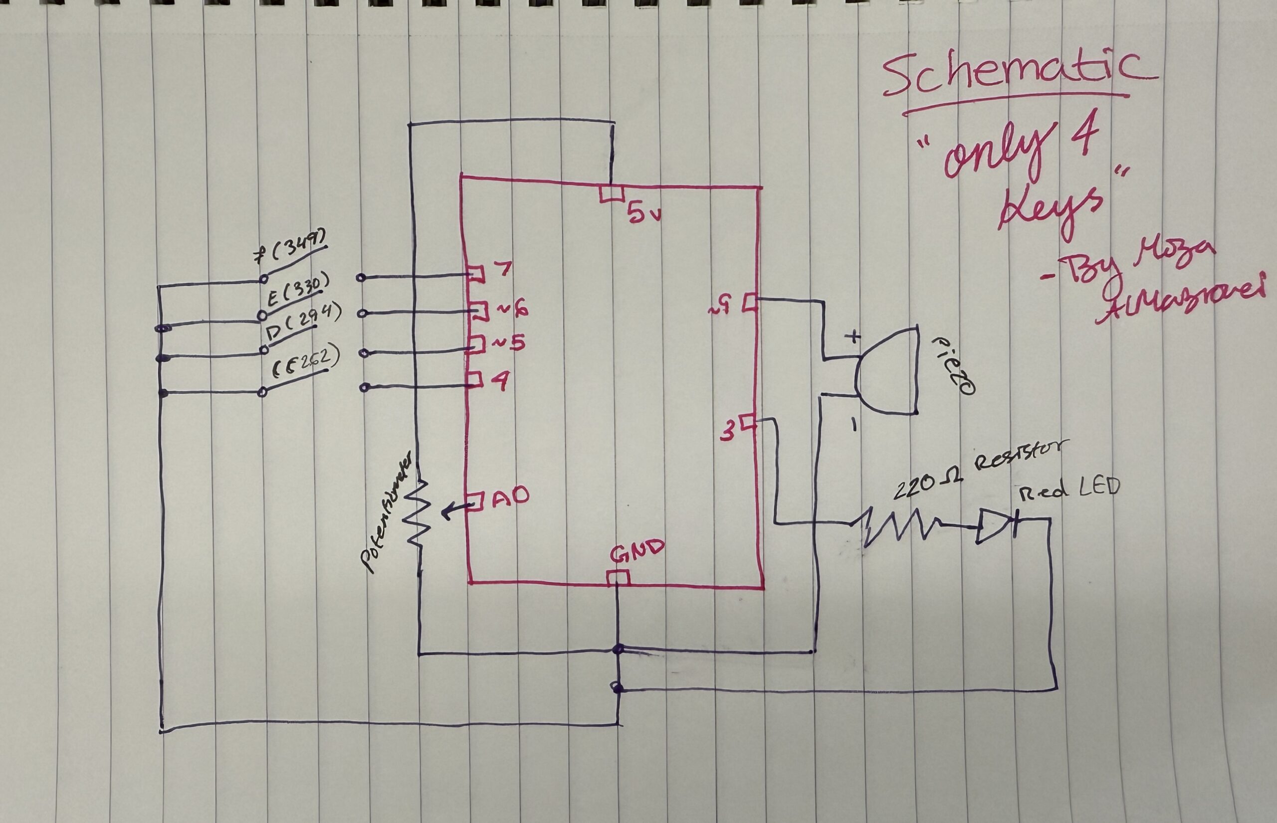
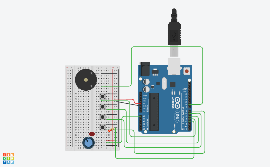
Hand-drawn schematic:

How this was made:
Schematics became easy for me to draw now after so many tries and practices in the old projects we created!!!

Image: Link to TC and Link to the video demo

How this was made:
I really wanted to create something on tinkercad using sound! and I did! I really love how it turned out because not only can I personally explore and try different things but also I can create different music, sounds, etc.
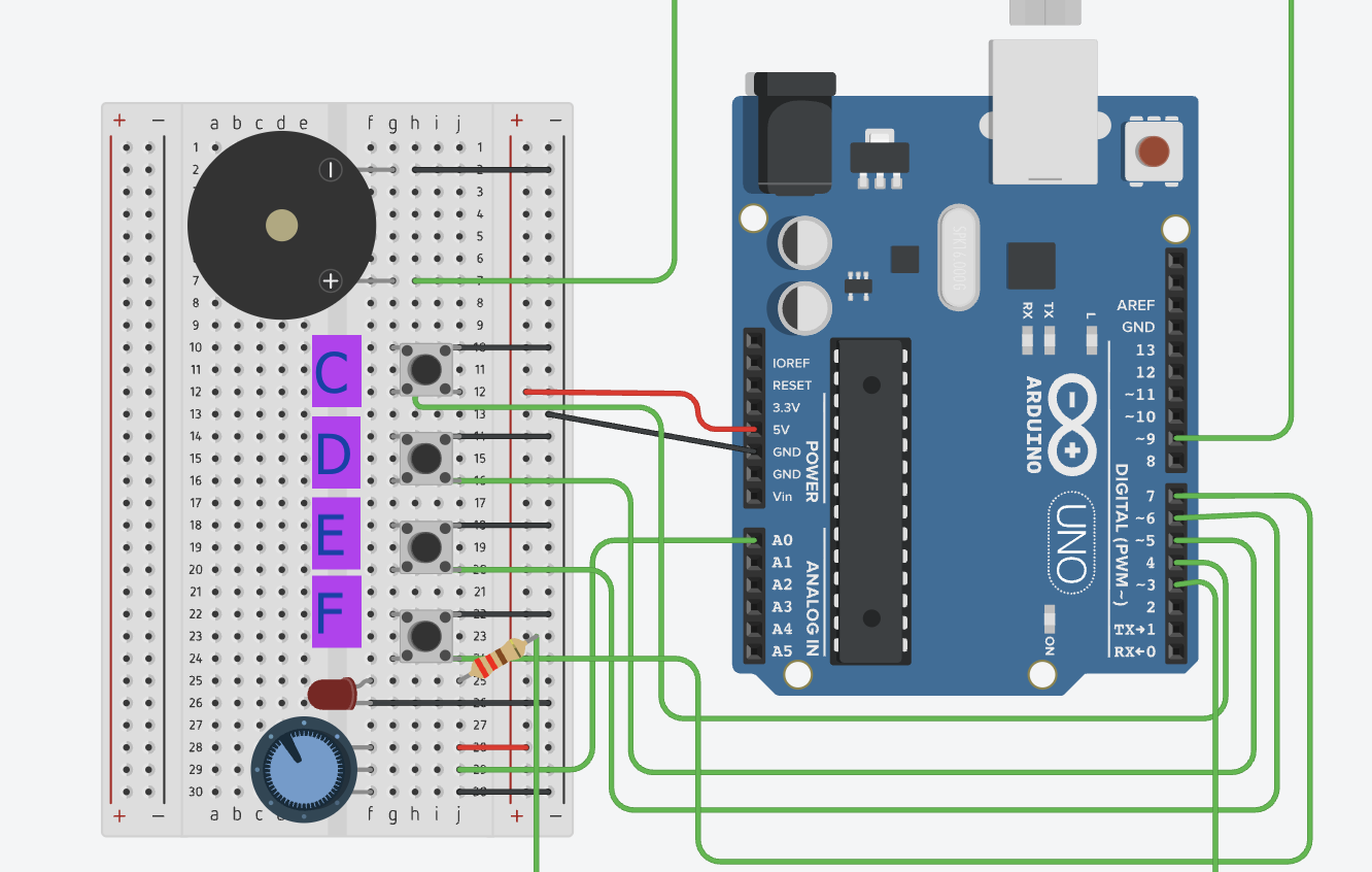
I started by building my project based on the the past projects I created and everything I learned. I wanted to improve and create something conceptually stronger and fun! I added the Piezo by connecting the positive side (h7) to pin ~9 using a green wire. I specifically used pin ~9 because it’s a PWM pin, which we learned in class is important for creating different sound frequencies and tones overall. Then I connected the negative side of the piezo (h2) to the negative side using a black wire. After making sure the GND was connected to the negative side and the 5V was connected to the positive rail, I moved on to the buttons. I added 4 buttons across the middle of the breadboard to act like mini piano keys. Each button plays a different note: Button 1 plays Note C, Button 2 plays Note D, Button 3 plays Note E, and Button 4 plays Note F. I connected one side of each button to the negative rail with black wires, while the other side connected to digital pins 4, 5, 6, and 7 using green wires. I also lined them up because I wanted the interaction to feel similar to pressing keys on a real keyboard or piano and also because of my actual design plan. For my final touch, I added a red LED as a visual indicator so that the interaction feels more alive instead of only relying on sound. I also placed the anode in f25 and the cathode in f26 then I connected a 220Ω resistor from the same row as the anode to Pin 3, and connected the cathode row to the negative rail with a black wire. THEN I shifted the potentiometer a little to the side so there would be enough space for the buttons while still keeping it close enough to work as the “tuning” dial for the notes. (overall the hardest part is always the placement because when we learn in class everything looks small but on the tinkercad it looks way bigger!)

Code:

// C++ code
//

void setup() {
  pinMode(9, OUTPUT); //the piezo speaker
  pinMode(3, OUTPUT); //red light
  
  //all the buttons
  pinMode(4, INPUT_PULLUP); //button 1=Note C
  pinMode(5, INPUT_PULLUP); //button 2=Note D
  pinMode(6, INPUT_PULLUP); //button 3=Note E
  pinMode(7, INPUT_PULLUP); //button 4=Note F
}

void loop() {
  int sensor = analogRead(A0);
  //changing the dial to a small number for the pitch
  int multi = map(sensor, 0, 1023, 1, 4); 

  //checking each button
  if (digitalRead(4) == LOW) {
    tone(9, 262 * multi); //play C
    digitalWrite(3, HIGH); //light turns on
  } 
  else if (digitalRead(5) == LOW) {
    tone(9, 294 * multi); //play D
    digitalWrite(3, HIGH);
  } 
  else if (digitalRead(6) == LOW) {
    tone(9, 330 * multi); //play E
    digitalWrite(3, HIGH);
  } 
  else if (digitalRead(7) == LOW) {
    tone(9, 349 * multi); //play F
    digitalWrite(3, HIGH);
  } 
  else {
    noTone(9); //silence when nothing is pressed
    digitalWrite(3, LOW); //light off
  }

  delay(10); //slow 10ms delay
}

How this was made:

For my code, in the setup first I highlighted pin 9 because that’s for the Piezo, my speaker which is the most important part of the project. I also set up pin 3 as an output for my Red LED, which is for the visual signal whenever a note is played and it becomes lighter and darker based on the button pressed. Then I set up pins 4, 5, 6, and 7 for my buttons while using INPUT_PULLUP so I wouldn’t have to add any extra resistors or wires on the breadboard since I can easily use Tinkercad’s built-in resistors. Then I created a loop and used analogRead(A0) to first check the sensor and then inside, because the dial gives a number from 0 to 1023, I used the map function (which I learned from ARDUINODOCS) to change that number into a small number that goes from 1 to 4. I called this multi (short for multiply) which allows me to change the pitch higher just by turning the dial. For the music, I used the if/else because again its familiar -p5.js. Because I wanted to create keys, I followed the musical notes of button 1 = 262 (a C note) and it goes on (of course I checked the music notes to do this). Inside each if statement, I also added digitalWrite(3, HIGH) so that the Red LED (connected with a 220Ω resistor to protect it) lights up at the exact same time the sound plays. I basically ended the code with else { noTone(9); digitalWrite(3, LOW); } so when no button is pressed, the sound stops and the light turns off. Like always, I added a 10ms delay at the bottom just to keep the loop from running too fast and making the sound glitchy.

Resources:

I just took tips from class, from youtube, from Professor Mang and Professor Aya’s notes!!

My creativity! Link to TC and Link to video

How this was made:
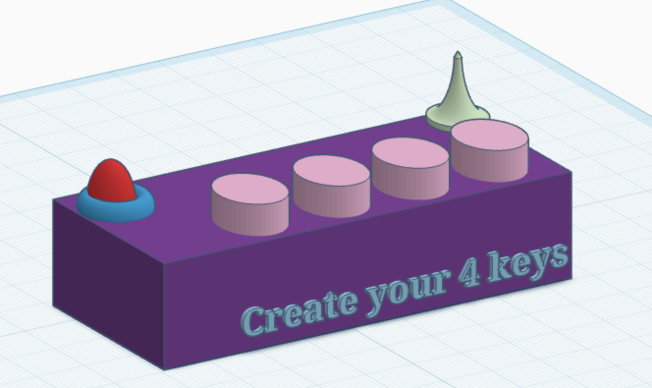
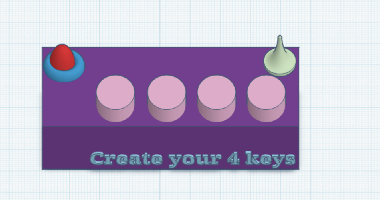
So of course, because I don’t have the actual kit 🙁 I had to use Tinkercad, and at first I was honestly sad because I felt limited when it came to creativity and design. But after Professor Mang told us that we could actually design the setup ourselves, I started exploring more inside Tinkercad and tried creating what I imagined the project would look like. Of course it’s still a bit different from how I would make it physically, but honestly that’s okay.

Overall what can you play -my experiment:

Mary Had a Little Lamb: E-D-C-D-E-E-E then D-D-D then E-E-E
Hot Cross Buns: E-D-C then E-D-C then C-C-C-C, D-D-D-D
Ode to Joy: E-E-F-F-E-D-C-C-D-E-E-D-D

Final reflection:
Honestly, I’m really proud of how this project turned out. At the beginning, everything felt confusing and overwhelming, especially because I didn’t have the physical Arduino kit and had to use Tinkercad -also with everything happening in the country 🙁 so overall the process wasn’t easy at all!

At first, I felt limited and thought it would make the experience less creative, but then I realized I could still experiment, design, and create something personal even in a simulation. Comparing myself from when I first started struggling through simple tutorials to now building an interactive project with buttons, sound, LEDs, and pitch control, I can honestly see how much I improved throughout the semester. What makes me happy  is that this project feels connected to me personally. I’ve always loved music, so creating my own mini “instrument” with only four keys was actually really fun. I also want to start finding a new hobby and learn piano! I also like that the project is simple but still allows people to experiment and create different patterns depending on how they interact with it. Even though it only has four buttons, it still allows people to show their creativity and curiosity.

I think one of the biggest things I learned from this project is that interaction design is not just about making something work technically, it’s about making the experience feel clear, engaging, and enjoyable for the person using it. I first did my project draft but after my sister played around with it she gave me feedback that allowed me to focus on specific user designs for my final. For future improvements, I would definitely want to expand the project by adding more notes, different sound effects, stronger visual feedback. Overall, I’m really happy I pushed myself further with this final instead of staying with something too simple, and I honestly want to keep experimenting more with Arduino and interactive design in the future.

Interactive Fluid Typography Experience Idea

For my final project, I will create an interactive fluid typography experience built in p5.js. For my midterm I made a game, so for the final I want to move in a different direction away from rules and goals, and toward something more expressive and open-ended. The project will let users interact with text that behaves like a physical, fluid material, responding to their cursor and input in real time. Letters and words will be broken down into particles that scatter, stretch, and reform based on mouse movement and clicks. The user won’t be trying to win anything, they’ll explore what happens when language loses its fixed shape.

Tools & Approach

  • p5.js for rendering and interaction

  • Font path decomposition to turn letters into manipulable point clouds

  • A particle system with spring forces so letters distort and snap back

  • Smooth morphing between words or phrases over time

Why This Project

This is a natural evolution idea from my midterm project, I’ve explored interactivity through game mechanics, now I want to explore it through pure experience design. Typography as material.

Final Project: My Secret Combination

“My secret combination, it’s a mystery for you.” Kalomira at the Grand Final of the Eurovision Song Contest 2008

Concept:

For my Final Project, I was very much inspired by my love for escape rooms. I love going to them and trying to figure out their unique puzzles. One thing I’ve always noted in escape rooms is that usually, you’re tasked to complete a few puzzles, and you’ll get a code, for which you twist the numbered padlock to escape. I wanted to take that concept and flip it, where you have to twist the dial, in order to get the code and escape.

Which is why, for my Final Project, I’ve created a game, which asks the player to figure out and enter the correct combination in order to win. The player needs to spin the potentiometers (which will be referred to as dials from this point onwards) and see at what value do the LEDs turn on. With all three LEDs, the player will get the secret code and can use to win! This project was mainly designed as a proof of concept of flipping the classic escape room idea, and hopefully escape room makers can implement it in the future!

Demo of the Final Project:

Design:
Link to the Tinkercad!

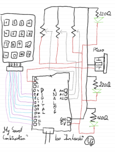
Hand Drawn Schematic:

How does the Project work:

For the beginning of the code, we need to create our own custom Digital Keypad, using the Keypad.h library. For this section a special mention and credits goes to Domingo Martinez, for explaining the code and helping me understand how to use the library. Using the keypad library, we can make a 2D array where we can define each key of the keypad. And then we can use the Keypad function to create our own keypad based on the number of columns, rows and also the aforementioned 2D array.

//Adding in the relevant library for the Keypad
#include <Keypad.h>

//Defining the number of Rows and Columns for our Keypad
//Credit to Domingo Martinez for explaining the code for Keypads: https://youtu.be/sPhcOm3FdOQ
const byte ROWS = 4;   
const byte COLS = 4;   

//Creating a 2D Array for our Keypad as that's how it is structured
char hexaKeys[ROWS][COLS] = {  
  {'1','2','3','A'},  
  {'4','5','6','B'},  
  {'7','8','9','C'},  
  {'*','0','#','D'}  
};  

//Here we're saying to which pins the Keypad is connected to
byte rowPins[ROWS] = {13,12,11,10}; 
byte colPins[COLS] = {9,8,7,6};     

//Creating our own custom Keypad Map
Keypad customKeypad = Keypad(makeKeymap(hexaKeys), rowPins, colPins, ROWS, COLS);

Then we need to define the pins which we’re using for the LEDs, Piezo and the Dials. I’ve discovered you can define multiple of them in a list so I went with that approach. Also I took the liberty of creating our secret code here, being the target numbers, and also the last dial values. These numbers will be updated constantly as the user twists the dials and saves them so that the program can later use them.

//Here we can define some constants for each of our connected pins
const int dials[3] = {A0, A1, A2};
const int leds[3] = {5, 4, 3};   
const int piezo = 2;

//This will be the secret code the player needs to get
const int targetNumbers[3] = {4, 7, 2}; 

//This is a list which will update based on the values that the user gets from twisitng the dials
int lastDialValues[3]   = {0, 0, 0}; 
String enteredCode = "";

Created a small function for the Piezo, as we need to dynamically update its frequency, duration and tone, for our different sounds.

//A simple function just to define the sound for the Piezo
void tonePiezo(int freq, int duration) {
  tone(piezo, freq);
  delay(duration);
  noTone(piezo);
}

Within the Setup function, I’ve defined the serial communication, and to constantly loop in order to check the output for the LEDs and the Piezo. Also wrote a little starting message for the player in the serial monitor and kinda gives off a notification to the user that the game has started.

//Our main setup function, starting off with the serial communication
void setup() {  
  Serial.begin(9600);
  
  //A for loop which checks for each LED its output as we want to constantly update
  for (int i = 0; i < 3; i++) {
    pinMode(leds[i], OUTPUT);
  }
  pinMode(piezo, OUTPUT);
  
  //Just prints a text saying the user can start to crack the code
  Serial.println("Unlock the Code!! Twist dials to find the code.");
}

Now, we get our handy loop function. In the first part of it, I’ve created a big for loop as I want it constantly check each of the three potentiometers and see their values update. Firstly, we read the Dials’ values, then we create mapped values for each dial, using the map function. This will simply take the values of the dials, and turn them into numbers from 1 to 9, so they can be used for our keypad later. As the user twists the dial, the code checks the current mapped dial value with the previous one and updates the serial monitor with some text accordingly. This is so the user is aware what the current value of the dial is. The finally, if the mapped dial value is the same as one of the target number values, or our code, then the LED will flash, indicating to the user that they’ve gotten it correct.

//Here is where the meat of it will happen,
void loop() {  
  //Using a for loop to check for all three Potentiometers
  for (int i = 0; i < 3; i++) {
    
    //We read each potentiometer and get its value
    analogRead(dials[i]); 
    delay(5);
    int dialValue = analogRead(dials[i]);
    
    //Then we map its value using the map function
    int dialMap = map(dialValue, 0, 1023, 1, 9);
    
    //Now for each Dial, we just check if its the same as the previous value and update it with the current value
    if (dialMap != lastDialValues[i]) {
      Serial.print("Dial ");
      Serial.print(i + 1);
      Serial.print(" is now at: ");
      Serial.println(dialMap);
      lastDialValues[i] = dialMap; 
    }
    //If the value that we are on the potentiometer is the same as the value of the secret code, then the LED turns on
    if (dialMap == targetNumbers[i]) {
      digitalWrite(leds[i], HIGH);
    } else {
      digitalWrite(leds[i], LOW);
    }
  }

Now the second part of the loop function is purely dedicated to the keypad. We take our custom keypad we built above and use it for various different things. Firstly we need to give feedback to the user that they’ve pressed a button on the keypad, which is done by virtue of the first if statement. Then we add that pressed key to our string, which is used for a few things in order to check if the played got the code or not. Firstly it checks for its length, which must be three for three dials. Then we check if the string is the same as the target numbers of our secret code. If the player got the right code, we output a victory message with a happy sound effect, if not, then a error message with a buzzing sound to indicate the player is wrong.

  //From the custom keypad we make a character from the key pressed, so it will displayed
char customKey = customKeypad.getKey();

//A simple if statement that prints out the key for the user, and also uses for the ente
if (customKey) {  
  Serial.print("Key Pressed: ");
  Serial.println(customKey);
  
  //This adds the character that came from the keypad to the string
  enteredCode += customKey; 
  
  //This is just a short sound from the Piezo which is meant to serve as like feedback for the user
  tonePiezo(500, 50); 
  
  //Checks if the code is 3 characters
  if (enteredCode.length() == 3) {
    //And here we check if the secret code is the same as what the user entered
    String secretCode = String(targetNumbers[0]) + String(targetNumbers[1]) + String(targetNumbers[2]);

    //Checks if the entered code is correct or not
    if (enteredCode == secretCode) {
      Serial.println("You have guessed the combination! You win!");
      playVictorySound();
    } else {
      Serial.println("That's wrong! Try again.");
      tonePiezo(200, 500); 
    }
    //Resets the player inputted code so they can try again
    enteredCode = ""; 
  }
}

This final part is our victory sound function. I’ve used Google Gemini for this part as I had no knowledge at all of how to create it. But it was useful to understand as the way it’s done is with a list that plays each sound frequency in order, with a bit of a delay between each sound so that the sounds can be propely heard.

//Plays a happy congratulatory sound
//Used Google Gemini to figure out the melody as I didn't understand how to make a melody 
void playVictorySound() {
  int melody[] = {262, 330, 392, 523}; 
  int duration = 150;
  
  //A for loop that goes through all the notes and plays them
  for (int i = 0; i < 4; i++) {
    tonePiezo(melody[i], duration);
    delay(50); 
  }
}

Parts that I’m quite proud of:

Honestly I think the part I’m most proud of was playing around with the keypad. I didn’t have any understanding intially as when I placed the keypad in, I actually I thought it would work automatically. But after watching that video that explained it I saw that you actually have to define a full on custom keypad for your own project. Also getting to know the map function was actually something I’m proud of to know now. In one of my previous projects, I’ve used the potentiometer but I needed to fiddle around with it in the code as it had a bit of noise. But understanding this, it really helped to have a specific concrete value for each part of the potentiometer and worked perfectly in the sense of making a keypad work functionally, with not much deviation.

Areas of Future Improvements:

I think probably the biggest area of improvement is implementing it in a p5js sketch so that it can look visually appealing. Of course the limitation in Tinkercad was definitely a factor but I think I could definitely build this and make a sketch in p5js so that the player can have a visual experience with it. Another approach I was going for initally was with an LCD panel, but I had a few issues in understanding the LCD panel on its own, and also I didn’t have enough pins on my Arduino so I can add it in. Definitely one possible way to improve it as while the serial monitor does do it justice, this would be a much more visually appealing way to go about it.

Reflecting on the Final Project:

I’m very pleased that the entire project in the end worked overall correctly and all parts that I’ve put worked synchronously. And I think getting rid of the buttons actually made more sense as there is an element of discovery for the player and I think giving a button to confirm it kinda ruins the magic of figuring out what the dial and subsequent LED lighting means. I’m quite gutted that I couldn’t implement the LCD panel into it due to issues I’ve had with it. If I had extra time, I could probably figure out some sort of way to implement it with some sort additional pins to the Arduino and get it working, but time is of the essence at the moment.

But this project has really taught me how escape rooms kind of balance an equilibrium of interactivity with the player, but also not being as very obvious and letting the player discover parts on their own. Even looking back at the puzzles I’ve done in escape rooms, I can understand clearly why the main aim is discovery of the puzzles and to have an interactive design so it sparks the curiousity for the player. For this project’s user testing, I believe I’ve gotten that approach, as my tester figured out some of the components. They were able to discover their functions and with a little curiousity, were able to figure out what was needed to be done to solve the puzzle.

Thoughts overall for this course:

While this section isn’t needed I thought I’d give a bit of a paragraph of thought for this introductory course. Going into it I had no idea what I’m getting myself into as I didn’t understand what Interactive Media represented. But I think the course really captured that idea of how with a little code, creativity and interacting with different tools, we can craft some fun experiences for anyone to enjoy. The readings as well gave me a very nice and different way of thinking when it comes to how we design and interact with various different products. Genuinely I really enjoyed this course and I want to extend a heartfelt thanks to Prof Mang for his support and constant love for getting us to become curious thinkers and interactive designers. Even with the course moving remotely, I think genuinely appreciate having supplementary options to still follow along and be a part of the course. I can only hope to take more Interactive Media courses in the future!

Signing off for Intro to IM, Spring 2026 with Prof Mang, I wish all of you an amazing summer break, and make sure to take care of yourselves, keep being curious and make sure to stay awesome always!

Ian Jarchevski

Full source Code:

//My Secret Combination
//Ian Jarchevski 04.05.2026
//Intro to IM, Final Project

//Adding in the relevant library for the Keypad
#include <Keypad.h>

//Defining the number of Rows and Columns for our Keypad
//Credit to Domingo Martinez for explaining the code for Keypads: https://youtu.be/sPhcOm3FdOQ
const byte ROWS = 4;   
const byte COLS = 4;   

//Creating a 2D Array for our Keypad as that's how it is structured
char hexaKeys[ROWS][COLS] = {  
  {'1','2','3','A'},  
  {'4','5','6','B'},  
  {'7','8','9','C'},  
  {'*','0','#','D'}  
};  

//Here we're saying to which pins the Keypad is connected to
byte rowPins[ROWS] = {13,12,11,10}; 
byte colPins[COLS] = {9,8,7,6};     

//Creating our own custom Keypad Map
Keypad customKeypad = Keypad(makeKeymap(hexaKeys), rowPins, colPins, ROWS, COLS);  

//Here we can define some constants for each of our connected pins
const int dials[3] = {A0, A1, A2};
const int leds[3] = {5, 4, 3};   
const int piezo = 2;

//This will be the secret code the player needs to get
const int targetNumbers[3] = {4, 7, 2}; 

//This is a list which will update based on the values that the user gets from twisitng the dials
int lastDialValues[3]   = {0, 0, 0}; 
String enteredCode = "";

//A simple function just to define the sound for the Piezo
void tonePiezo(int freq, int duration) {
  tone(piezo, freq);
  delay(duration);
  noTone(piezo);
}

//Our main setup function, starting off with the serial communication
void setup() {  
  Serial.begin(9600);
  
  //A for loop which checks for each LED its output as we want to constantly update
  for (int i = 0; i < 3; i++) {
    pinMode(leds[i], OUTPUT);
  }
  pinMode(piezo, OUTPUT);
  
  //Just prints a text saying the user can start to crack the code
  Serial.println("Unlock the Code!! Twist dials to find the code.");
}  

//Here is where the meat of it will happen,
void loop() {  
  //Using a for loop to check for all three Potentiometers
  for (int i = 0; i < 3; i++) {
    
    //We read each potentiometer and get its value
    analogRead(dials[i]); 
    delay(5);
    int dialValue = analogRead(dials[i]);
    
    //Then we map its value using the map function
    int dialMap = map(dialValue, 0, 1023, 1, 9);
    
    //Now for each Dial, we just check if its the same as the previous value and update it with the current value
    if (dialMap != lastDialValues[i]) {
      Serial.print("Dial ");
      Serial.print(i + 1);
      Serial.print(" is now at: ");
      Serial.println(dialMap);
      lastDialValues[i] = dialMap; 
    }
    //If the value that we are on the potentiometer is the same as the value of the secret code, then the LED turns on
    if (dialMap == targetNumbers[i]) {
      digitalWrite(leds[i], HIGH);
    } else {
      digitalWrite(leds[i], LOW);
    }
  }
    //From the custom keypad we make a character from the key pressed, so it will displayed
  char customKey = customKeypad.getKey();
  
  //A simple if statement that prints out the key for the user, and also uses for the ente
  if (customKey) {  
    Serial.print("Key Pressed: ");
    Serial.println(customKey);
    
    //This adds the character that came from the keypad to the string
    enteredCode += customKey; 
    
    //This is just a short sound from the Piezo which is meant to serve as like feedback for the user
    tonePiezo(500, 50); 
    
    //Checks if the code is 3 characters
    if (enteredCode.length() == 3) {
      //And here we check if the secret code is the same as what the user entered
      String secretCode = String(targetNumbers[0]) + String(targetNumbers[1]) + String(targetNumbers[2]);

      //Checks if the entered code is correct or not
      if (enteredCode == secretCode) {
        Serial.println("You have guessed the combination! You win!");
        playVictorySound();
      } else {
        Serial.println("That's wrong! Try again.");
        tonePiezo(200, 500); 
      }
      //Resets the player inputted code so they can try again
      enteredCode = ""; 
    }
  }
  
  delay(10); 
}
//Plays a happy congratulatory sound
//Used Google Gemini to figure out the melody as I didn't understand how to make a melody 
void playVictorySound() {
  int melody[] = {262, 330, 392, 523}; 
  int duration = 150;
  
  //A for loop that goes through all the notes and plays them
  for (int i = 0; i < 4; i++) {
    tonePiezo(melody[i], duration);
    delay(50); 
  }
}

for scrolling all the way down, here’s a cat spinning on a record player 😀


User Testing

I built the most part of my project, and now I just need to tune up the visual aesthetics of it on the screen, and to mount the controls up on the panel that is external to the breadboard.

I asked my mom to test my project, but I can’t say that the this is really representative because language was a bit of a barrier in understanding this experience.

However, I tested it anyways and I also gained some insight. It was obvious even on the breadboard with no labels at all that you need to click, rotate, tune and just keep doing something with the controls to run the experience. My mom sat down and immediately started tryng to hold, press, toggle, rotate different buttons and the potentiometer, so I think this is really obvious but I will need to label the buttons with “HOLD” or “PRESS ONCE” because it was not really intuitive.

I also noticed that she mostly was looking at the breaboard and controls and didn’t pay much attention to the screen or music there, probably waiting for some physical output. To fix that I think I will need to position the panel and the screen in a certain way, so the panel feels like the “keyboard” for the screen and the user understands that they need to look at the screen in order to understand what happens. Also, maybe having earphones as a part of the experience also will make the user pay more attention to the sound and audio changes.

The fact that it is a musical instrument that controls audio and some particles on the screen. It was not obvious that these particles produce the sound though. So, I realized I need to have some animation on the screen when the note is triggered so it is more obvious.

As I said, I don’t think my user was too focused, but this also gave me the insight of making the experience more isolated: to have screen and panel on in one place and close to each other, and offering headphones so the user is actually paying attention to the project and don’t ignore it.

Also, labeling the controls with “HOLD” or “PRESS ONCE” but maybe avoid labeling what they directly do and label it more vaguely. I feel like my mom was actually curious to figure out what each thing does so she kept tinkering with it so I guess this is a nice part of the experience I didn’t expect.

I needed to explain in the end what’s the idea of the experience, so I figured that maybe I need to run some “intro” on the screen, so the user gets the idea of what is happening, and then run the experience itself. And also more visual feedback would be a big change because it will give the user the idea of how what they do is impacting the sound I think.

I will work on the p5 visual part for now to make the design visually responsive, and add LEDs and button labels on the physical panel once new knobs and some additional equipment arrive.

Video on Google Drive

Week 13 – User Testing – Kamila Dautkhan

During the user testing, some people felt confused at the beginning. They didn’t understand that the big number in the center was the real, live Bitcoin  price updating from the internet. Some thought the sound was just random background music and didn’t realize their mouse movement was controlling the pitch and volume. They also didn’t know that the sound changing from smooth to rough was connected to market volatility. Overall, the project felt fun but needed clearer explanations about what the price, mouse controls, and sound changes actually represented. I think this experience clearly showed that without knowing its real market data, people enjoy it as a generative toy but miss the deeper meaning. Here is the video:

IMG_4224