PRESSYR – User Testing Reflection
VDO:
https://youtu.be/GeI6QWZyzsk?si=tPqhPQI3fib59SSb
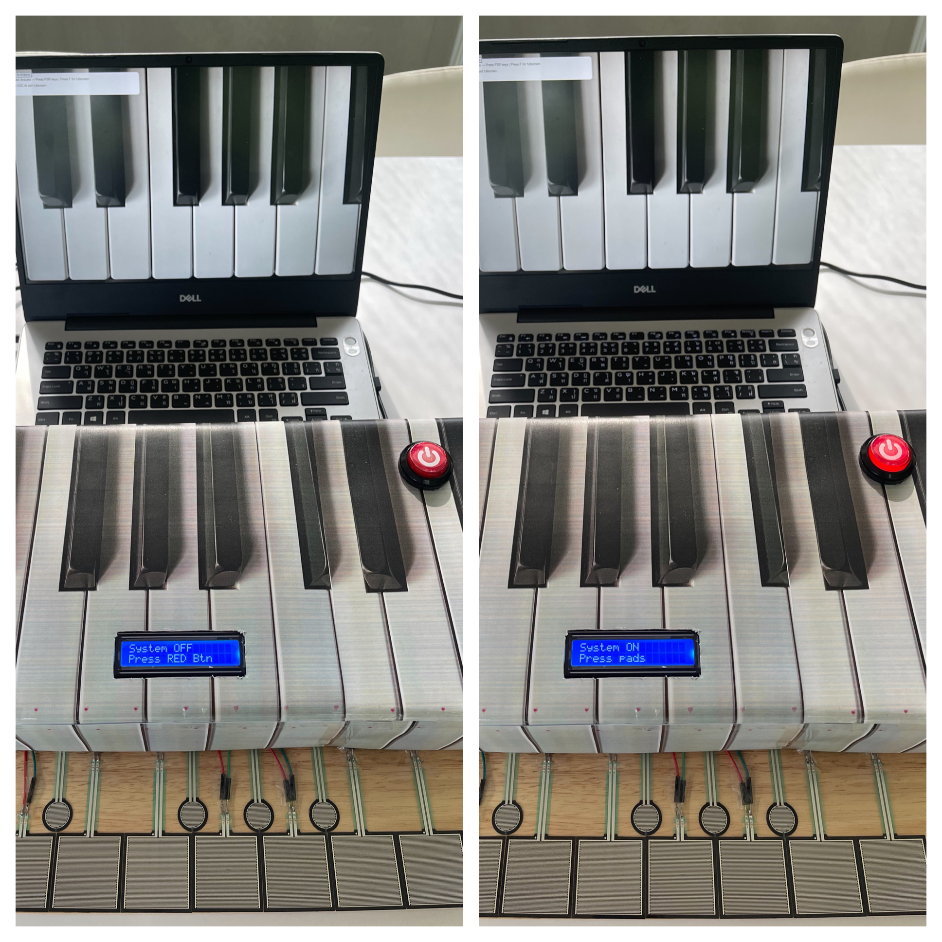
For my final project, I created an interactive piano-inspired instrument called PRESSYR using Arduino, FSR pressure sensors, a CD74HC4067 multiplexer, an I2C LCD display, an arcade power button, and a p5.js visual and sound interface. The project allows users to press pressure-sensitive pads to play musical notes while also generating sound and visuals on a computer screen.
User Testing Process:
I conducted user testing with four participants. During the testing session, I intentionally did not give them detailed instructions at first because I wanted to observe how naturally they could understand and interact with the project on their own.
One thing I noticed immediately was that almost every participant was initially confused about what the device actually was. However, most of them could somewhat guess that it was related to a piano or music instrument because the cardboard enclosure visually resembled piano keys. In addition, my house already contains a real piano, and everyone who participated already knew that I play the piano, so this context may also have influenced their assumptions.
The main confusion at the beginning was understanding what to press first and how to start interacting with the system. Fortunately, the LCD screen helped guide users by displaying “Press RED Button” when the system was off. This instruction helped participants understand that the red arcade button was the actual starting point for interaction.
After turning the system on, some participants were still slightly confused about what to do next. I think this happened for two reasons. First, the instructions on the LCD were written in English, and second, some participants did not immediately understand what the word “pads” referred to. Even so, after a short moment of exploration, every participant eventually understood that the pressure-sensitive pads were musical inputs that played notes like Do, Re, Mi, Fa, Sol, La, Ti, Do.
Observations During Interaction:
One interesting observation from the testing session was that participants rarely looked at the computer screen visualizations while playing. Instead, they focused almost entirely on the physical pads and their hand movements.
I believe this happened mainly because users had to concentrate on pressing the pads accurately and listening to the melody from each key being produced. Since the sound feedback already confirmed that the interaction was working, participants did not feel a strong need to constantly look at the screen. The laptop screen was also positioned slightly farther away from the pads, which may have reduced visual attention even more.
Although it is possible that the visual effects on the screen were not large or attention-grabbing enough, I personally think the stronger reason was that users naturally prioritized the physical interaction and audio feedback over the visual component.
What Worked Well:
Several aspects of the project worked successfully during testing:
– The arcade power button clearly communicated the ON/OFF state of the system.
– The illuminated LED inside the arcade button provided immediate visual feedback.
– The LCD instructions helped guide users through the interaction process.
– The pressure-sensitive pads successfully triggered sound and visuals consistently.
– Users eventually understood the interaction flow without requiring direct explanation.
– The piano-inspired physical design helped communicate the musical concept of the project.
Areas for Improvement:
Some participants commented that the pressure pads felt larger than actual piano keys. This feedback was valuable because it highlighted how the scale of the interaction affected the realism of the experience.
In future versions of the project, I would like to:
– Reduce the size of the pads to better resemble real piano keys.
– Improve the visual prominence of the p5.js animations so users notice them more easily.
– Add clearer visual labels or symbols for first-time users.
– Experiment with different layouts and materials for a more polished interaction experience.
– Explore using velocity-sensitive audio or multiple sound layers for more expressive musical interaction.
Reflection:
This user testing session helped me realize how important clarity and interaction flow are in physical computing projects. Even though the project technically functioned correctly, small design decisions such as wording, placement of instructions, and physical scale strongly affected how users understood the experience.
Overall, the testing process was extremely useful because it revealed areas where the interaction was intuitive and areas where users still needed additional guidance. It also helped me think more carefully about how people naturally approach unfamiliar interactive objects for the first time.