Exercise 1
Demo:
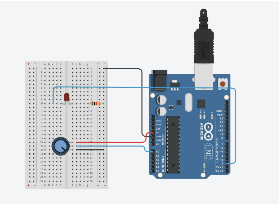
Schematic:
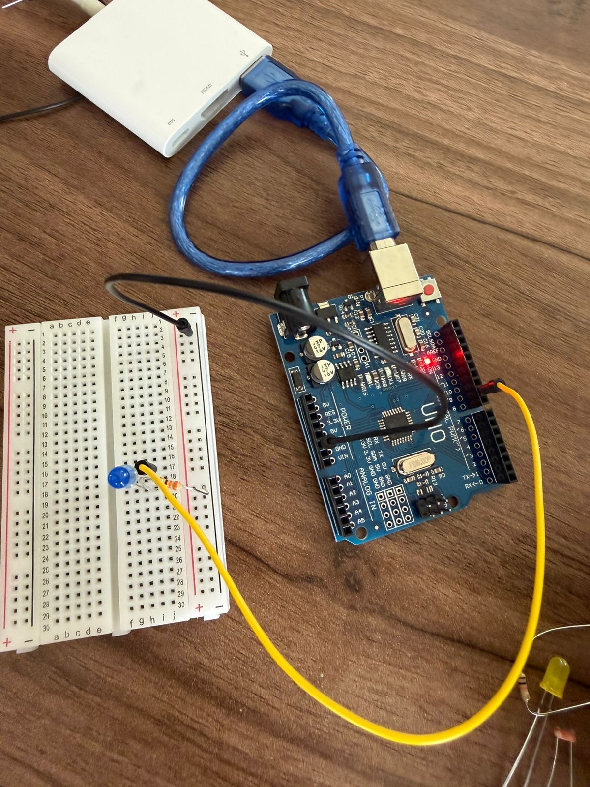
Implementation:
- Arduino
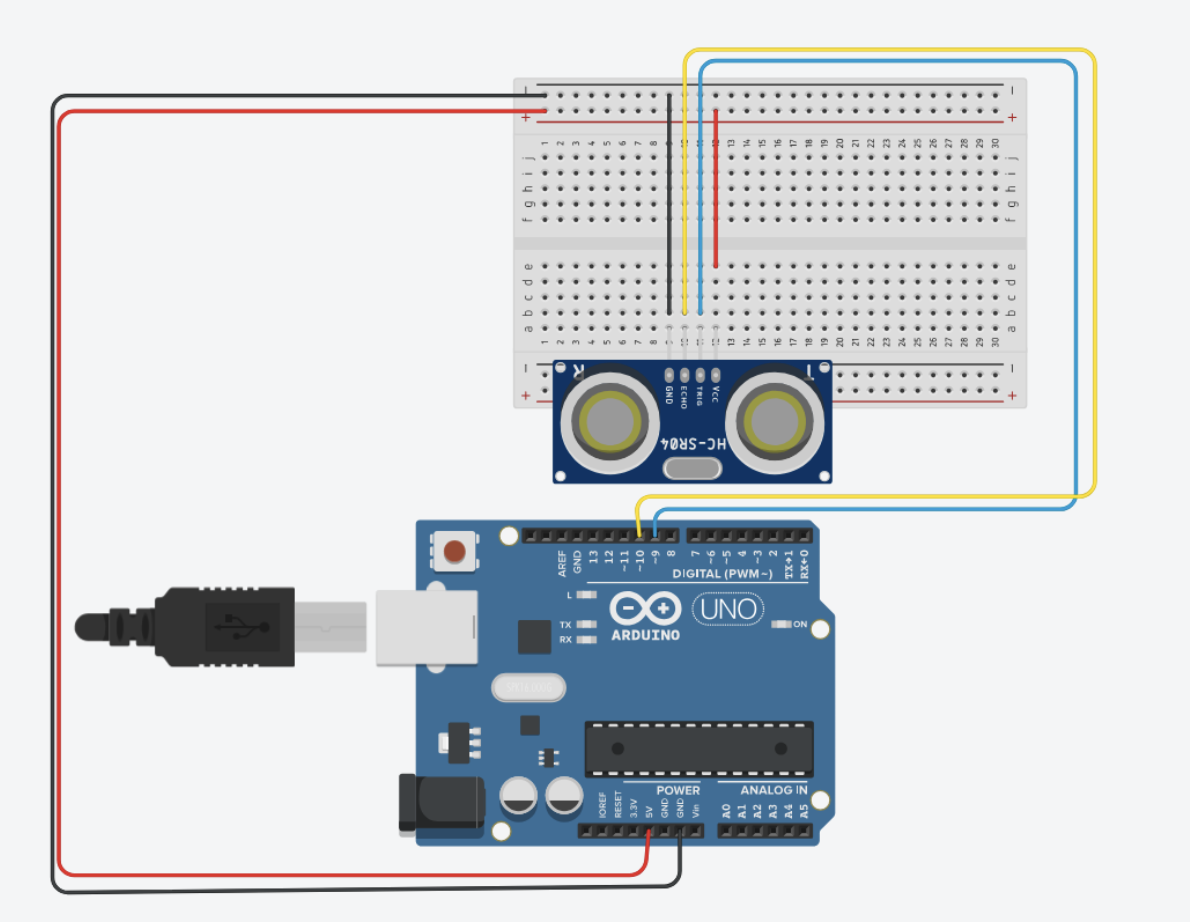
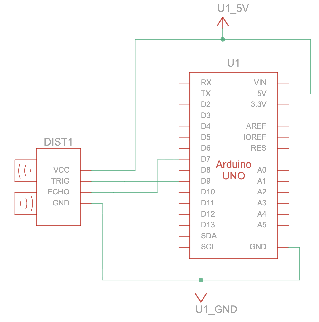
- I began by setting up a simple circuit with an ultrasonic sensor to control the circle’s position in p5 using my hand’s distance from the sensor.
- For the code, I used the same distance calculating code I used in one of my previous assignments that used the ultrasonic sensor. The only thing I changed is
void loop(){
//...
  Serial.println(mappedDistance);
//...
}
where I used println instead of just print, so that a new line is printed with every write to the serial monitor.
- p5:
- I used the same connection logic from the class example using the “click to connect” button. Then, I read from the serial monitor and convert the string it reads into a value. Then, I draw the ellipse and insert the x-value we read from Arduino into its appropriate place in the parameters.
Exercise 2
Demo:
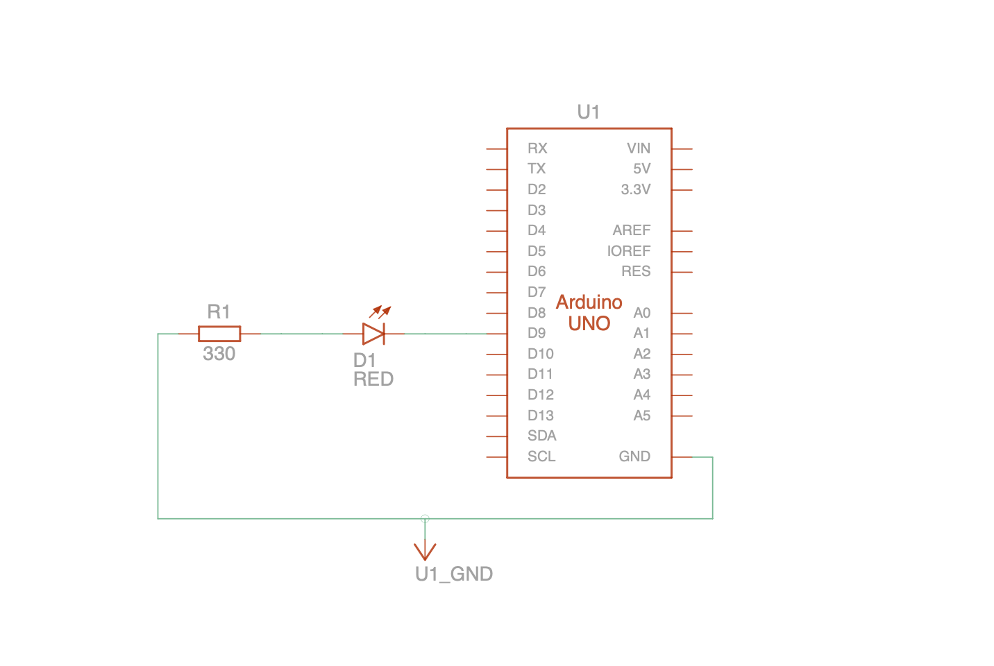
Schematic:
Implementation:
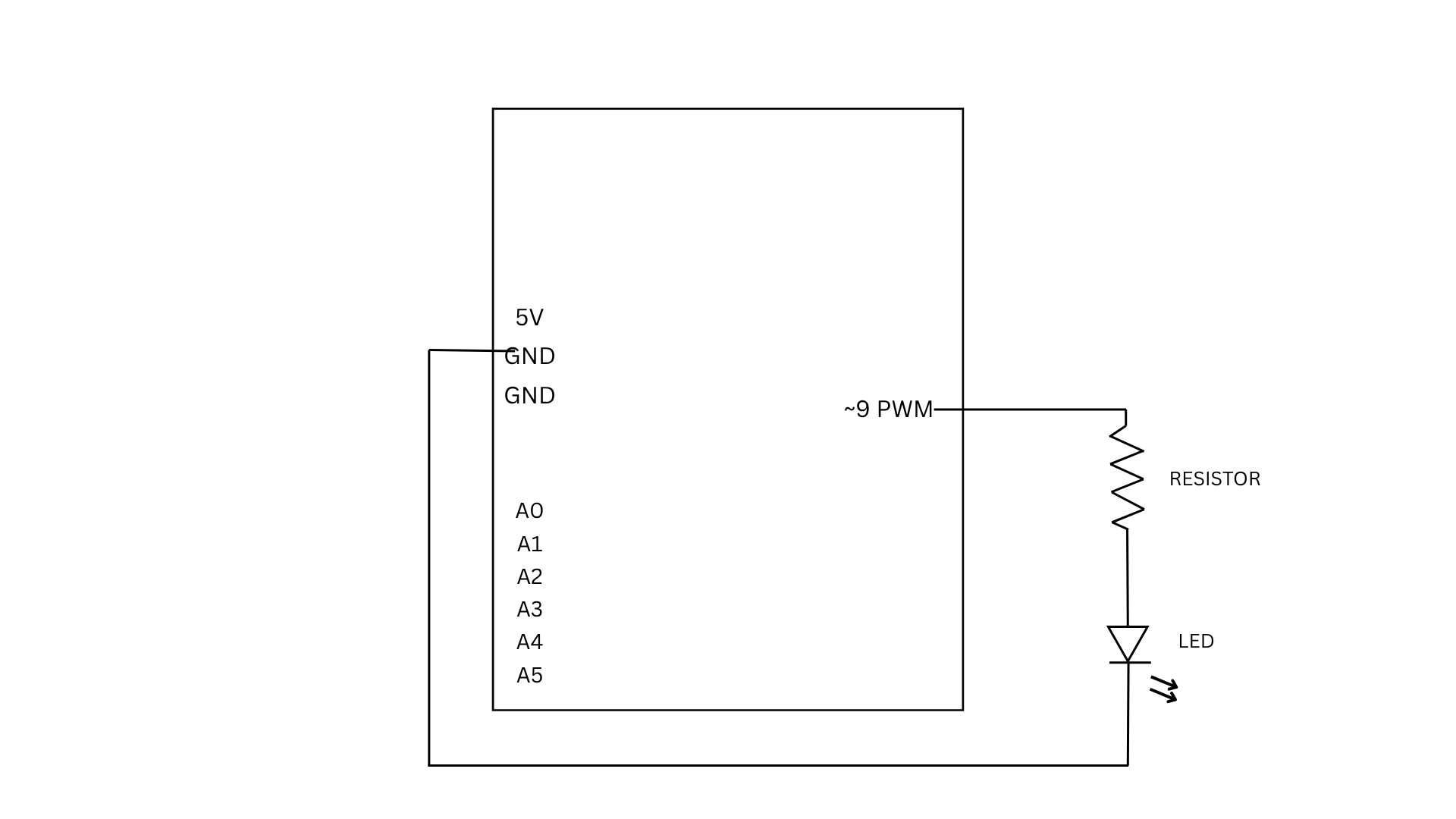
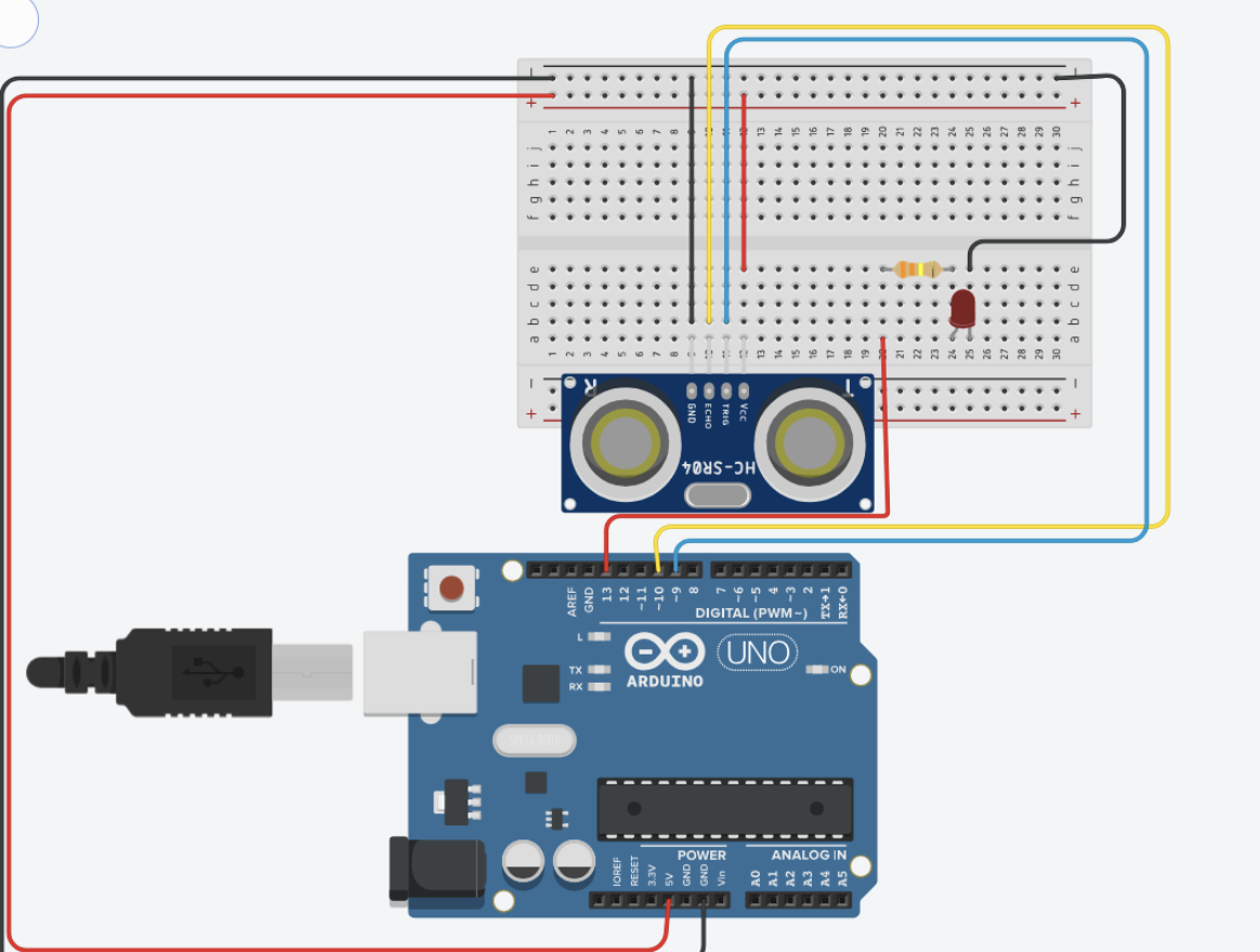
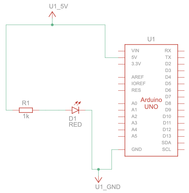
For this exercise, I used a slider on p5 to control the brightness of an LED on my Arduino.
- Arduino:
- I started by setting up a simple circuit with one LED light connected to pin 9
- For the code, it reads the incoming values from p5, then it constrains the incoming value to be between 0-255 to match the values for brightness, and then it analogWrites the value to the LED.
- p5:
- I used the createSlider() function to create a simple slider that controls the LED’s brightness. The slider ranges from 0-255 and by default sets to 127, the halfway point.
- I, again, used the connect button logic to prompt the browser to connect to the Arduino
- In the draw function, the slider’s value is read. If the port is open and the connection is established with the Arduino, then p5 sends the slider’s value as a string followed by a newline character “\n” so Arduino knows when a full value has arrived. It also displays the “Disconnect” text on the button if the port is open. If the port is closed, it shows “Connect to Arduino” on the button. The current brightness value is also displayed as text on the canvas
Exercise 3
Demo:
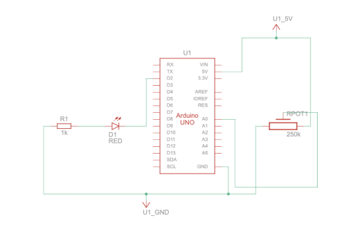
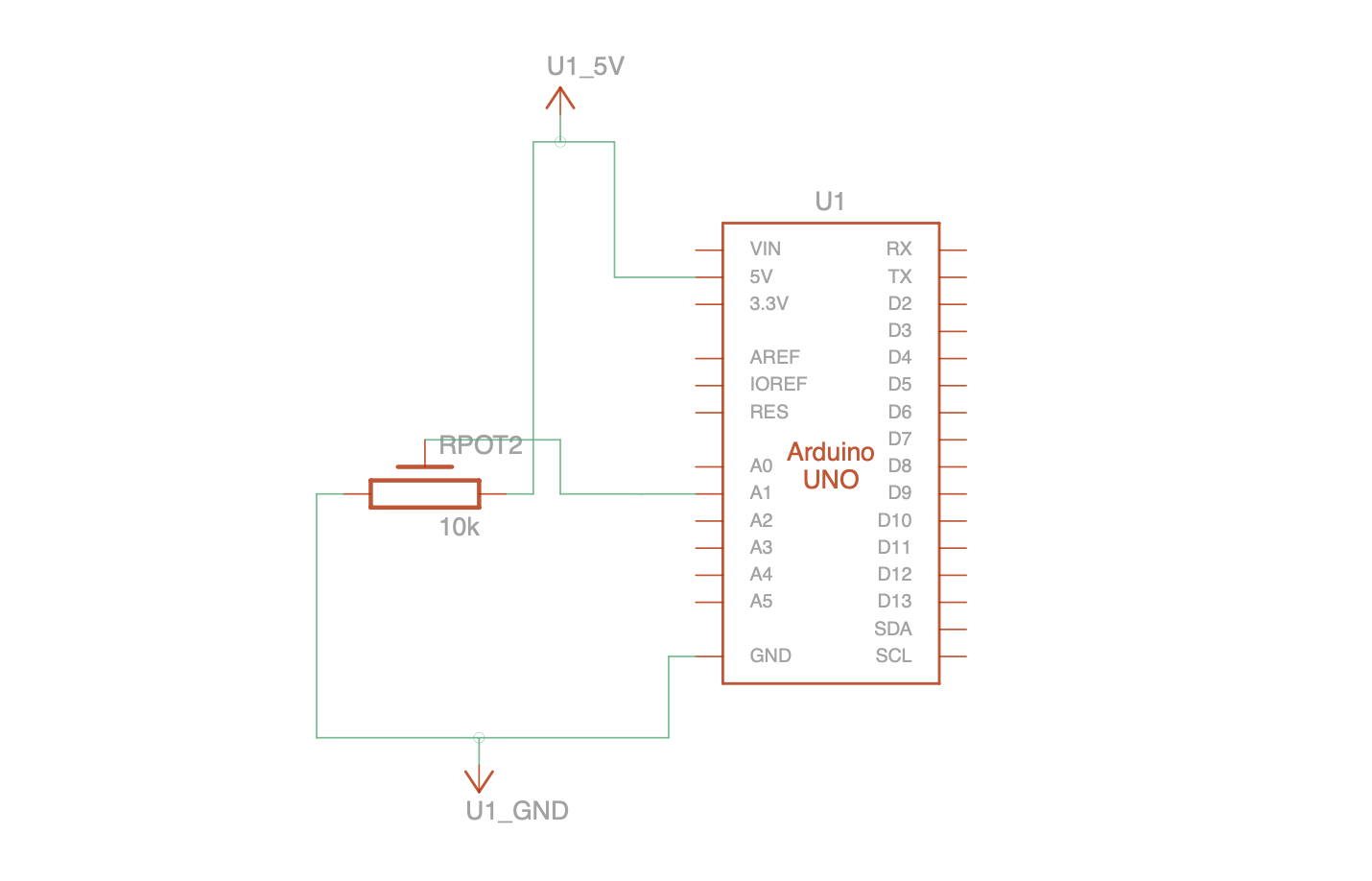
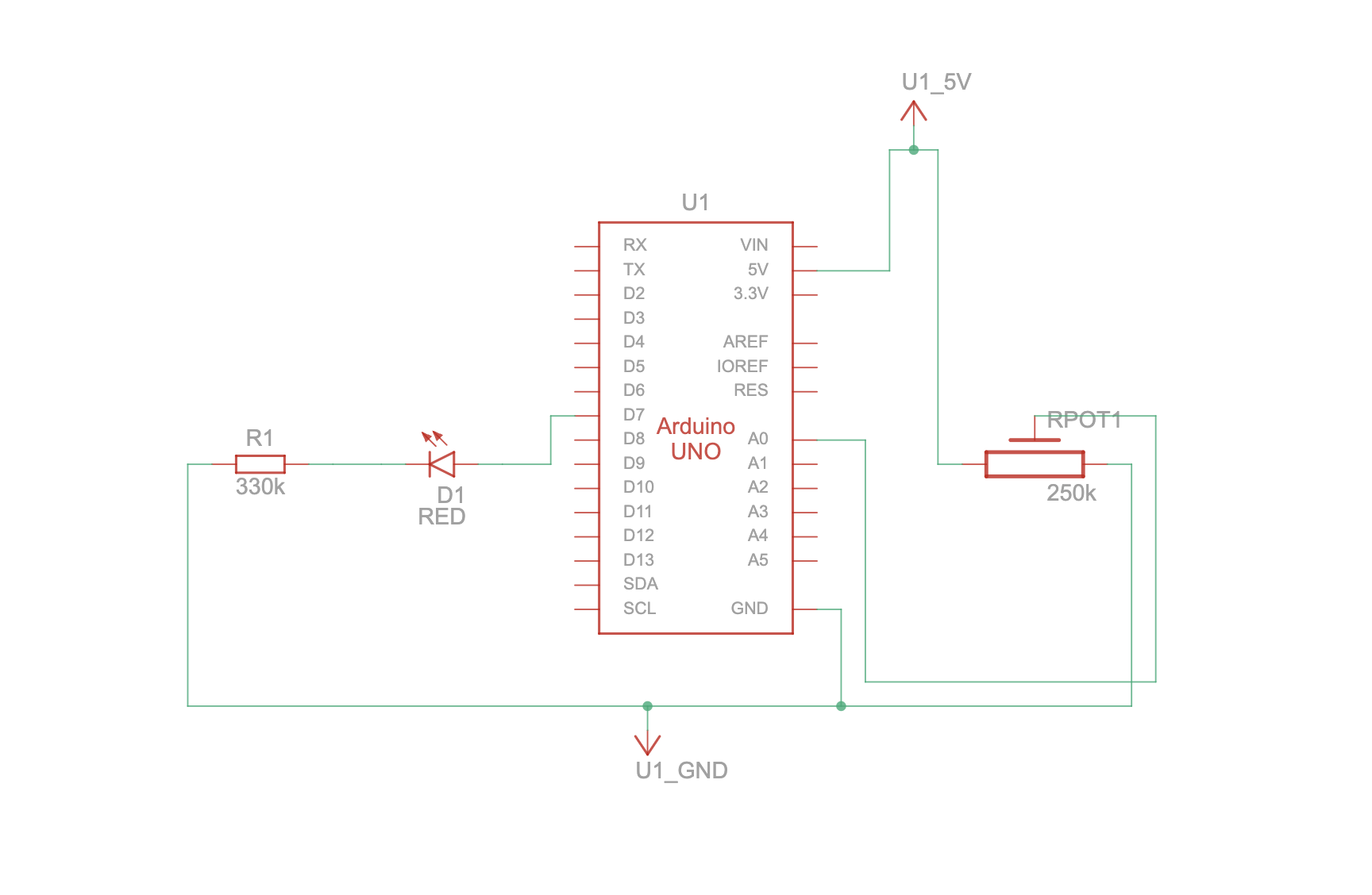
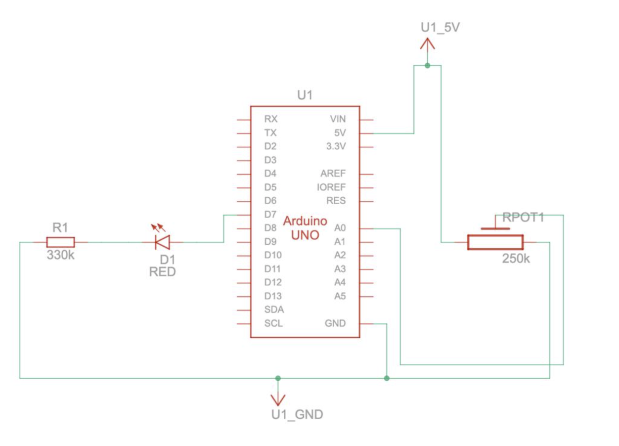
Schematic:
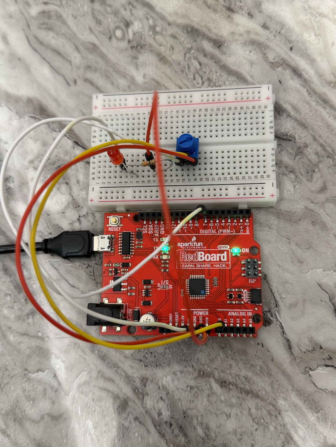
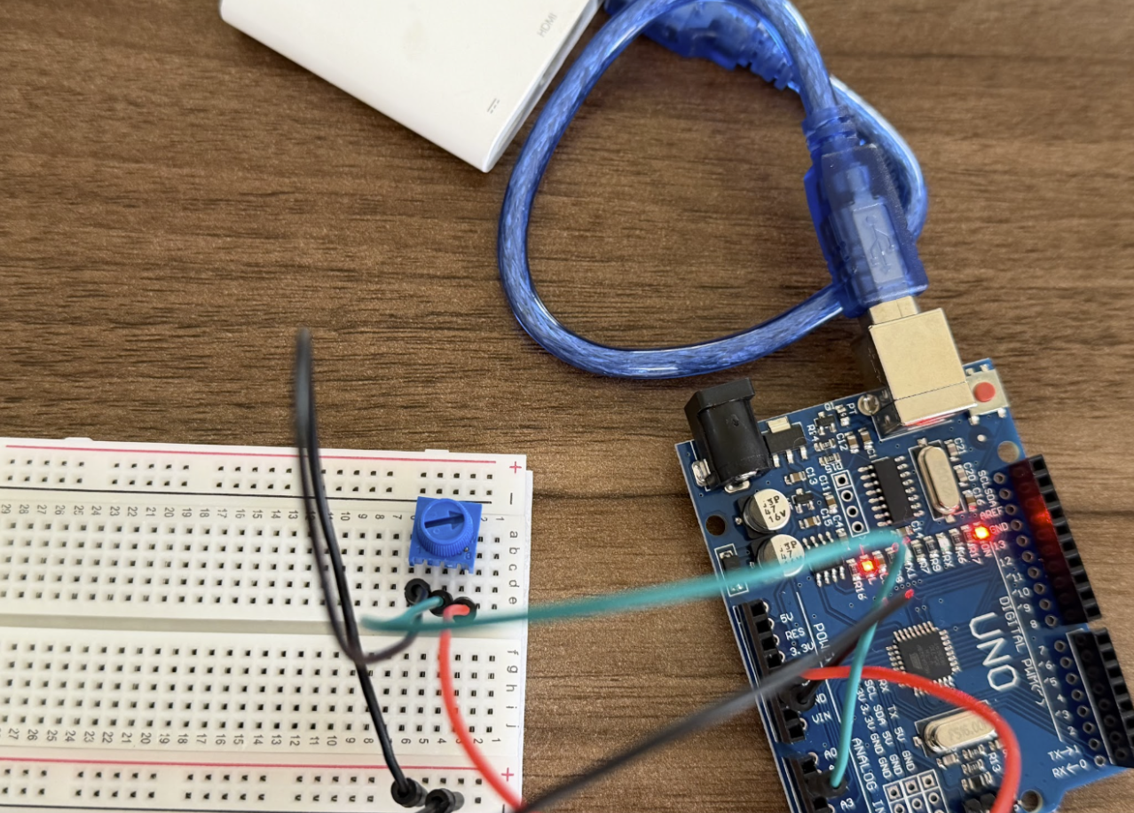
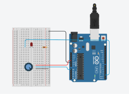
Implementation:
- Arduino
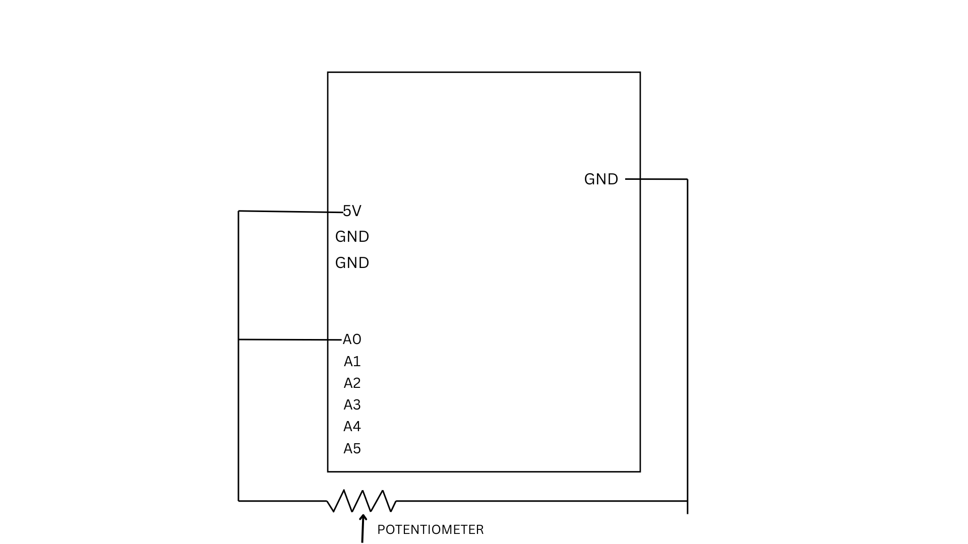
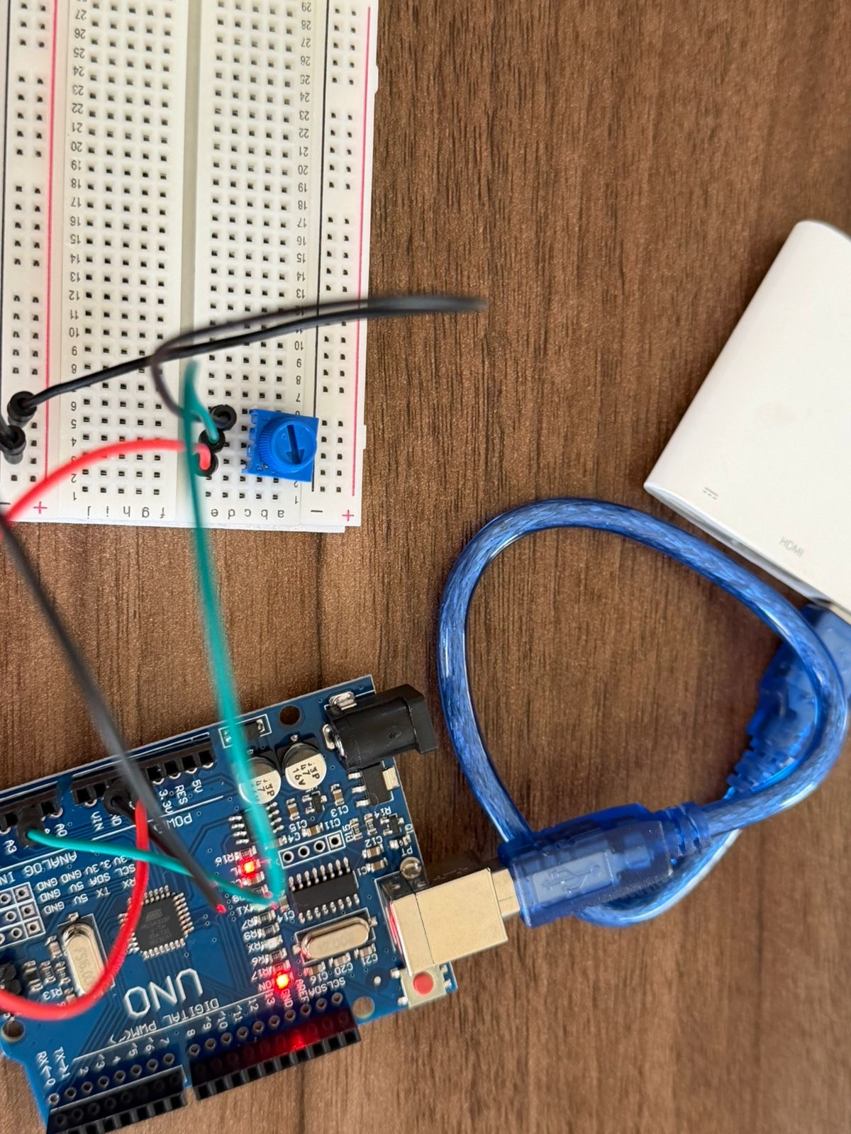
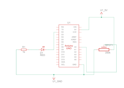
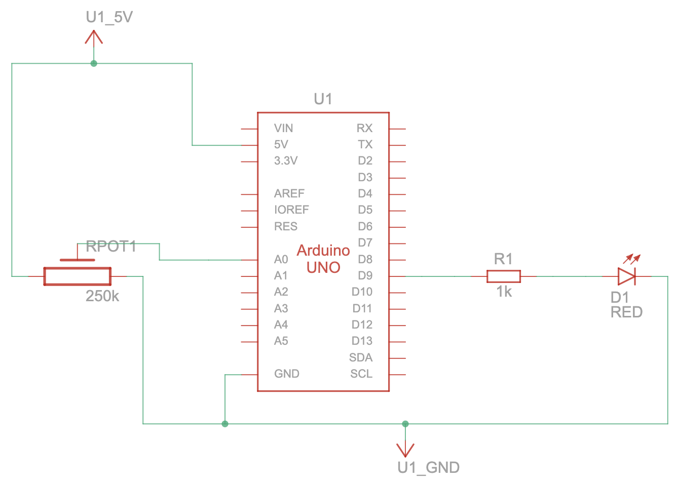
- For my circuit, I connected a potentiometer and an LED light to pins on the Arduino
- For the code, it can be divided into two main sections: sending information from the potentiometer to p5 and receiving information from p5 for the LED
- Potentiometer:
- It reads the potentiometer’s value
- It maps it from 0-1023 to -100-100 and divides my 100.0 to get a float value. This gives us a good range for the wind variable in the p5 sketch (-1 to 1)
- It prints the mapped value to the serial monitor using println() to send the data to p5
- LED:
- It checks if data has been received and reads it
- If the data reads ‘H’ for HIGH, then it turns on the LED, else if it’s ‘L’ for LOW then it turns off the LED
- Potentiometer:
- p5:
- For the wind, it reads the value through the port from Arduino and just sets the wind’s x value to the pot’s value
- For the ball, when it hits the bottom of the screen it sends an ‘H’ to Arduino to signal the LED to turn on, and when the ball is in the air it sends an ‘L’ to signal the LED to turn off.
Reflection
Due to the nature of the tasks and their specific requirements, I found it a bit difficult to get creative with my ideas for each exercise; however, they were an excellent way to familiarize myself deeply with serial communication and test my knowledge.