
Ideation
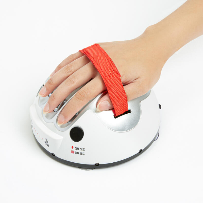
When I first started thinking about what to do for this project, I wanted to create something that was a bit playful (a bit gamified?), while also showcasing how analog and digital inputs can work together in a meaningful way. I landed on the idea of a “Human Lie Detector” — a lighthearted concept that mimics stress or honesty detection based on physical responses. This was inspired by an existing device that I often saw being used in Korean drinking games. For that machine, small electric shocks are sent the person who is attached to the machine based on the sweat produced by someone’s hand. Since I don’t intend to cause pain to any body I decided to use a sensor that could imitate the just of the lie detector idea. So, the pressure sensor became the core of the project, as it allowed me to measure subtle changes in finger pressure, which I imagined could simulate a person’s nervousness or calmness when answering a question. By combining this analog input with a digital button (to simulate the moment a person gives an answer), I could create a clear trigger point and decision logic for controlling the LEDs. The red and green LEDs became symbolic indicators: red for “lie” and green for “truth,” depending on how much pressure was applied.
Implementation
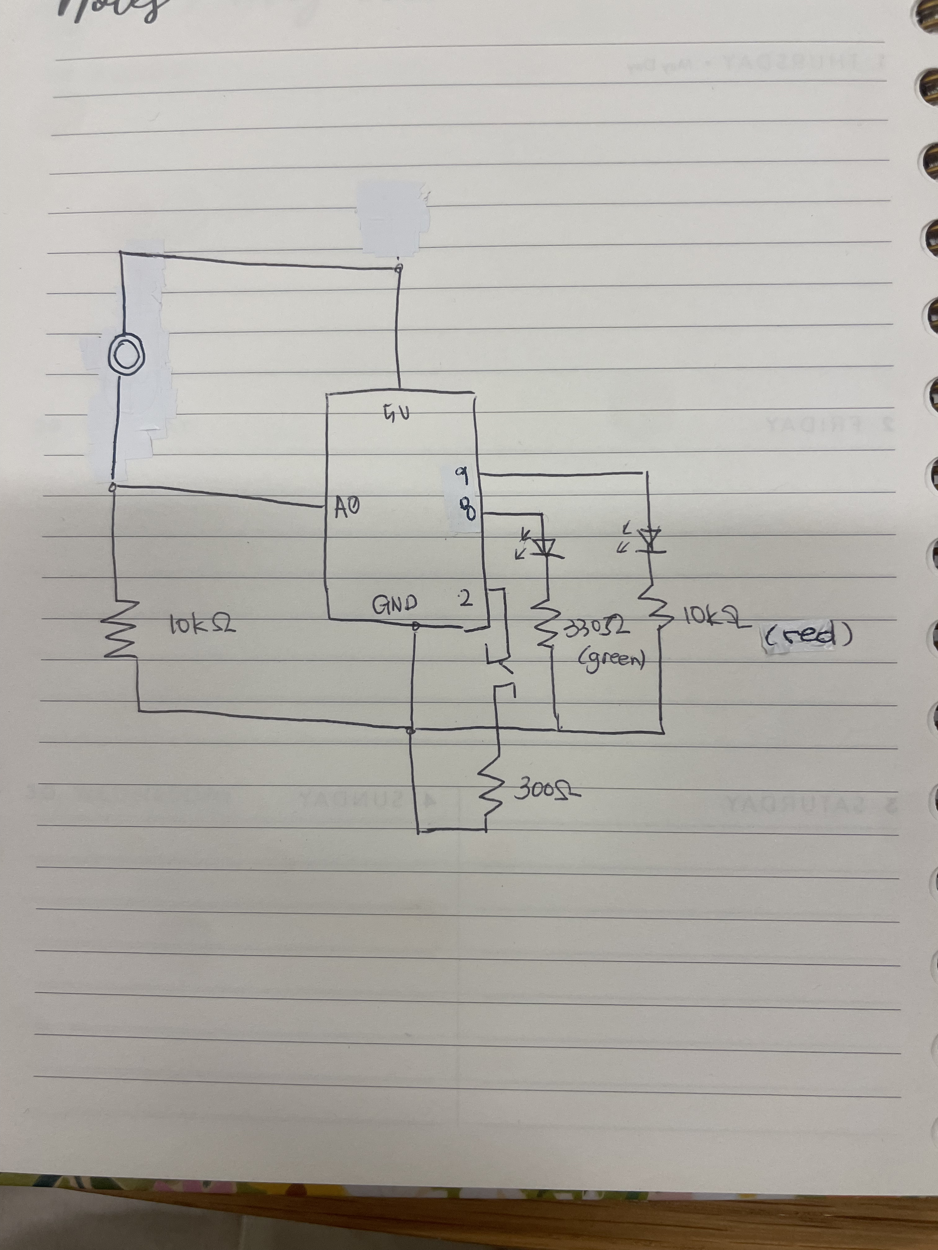
To bring the idea to life, I started by wiring up the core components: a pressure sensor, a pushbutton, and two LEDs (one red and one green). I used a 10k resistor to build a voltage divider circuit with the pressure sensor, allowing me to read its analog values through pin A0 on the Arduino. The pushbutton was connected to digital pin 2 and configured with Arduino’s internal pull-up resistor to simplify the circuit. For output, I connected the red LED to pin 8 and the green LED to pin 9. You can see the demo video below (sound ON):
IMG_0052
Here’s the schema I drew :

Code Highlights
One small but important part of my code was adding a mid-range threshold to control the green LED. At first, I noticed that the green LED would turn on even when there was barely any pressure on the sensor, just because the button was pressed. To fix this, I added a lower bound to the pressure range. So now, the green LED only turns on if the pressure is somewhere between a low (50) and high threshold (500). This simple change made the interaction feel a lot more accurate and intentional. It wasn’t a complex fix, but it solved an annoying issue and made the project work the way I wanted.
int threshold = 500;
int lower = 50;
.
.
.
if (buttonState == LOW) {
  if (pressureVal > threshold) {
    digitalWrite(redLED, HIGH);
    digitalWrite(greenLED, LOW);
  } else if (pressureVal > lower) {
    digitalWrite(redLED, LOW);
    digitalWrite(greenLED, HIGH);
  } else {
    digitalWrite(redLED, LOW);
    digitalWrite(greenLED, LOW);
  }
} else {
  digitalWrite(redLED, LOW);
  digitalWrite(greenLED, LOW);
}
initially wrong code:
if (buttonState == LOW && pressureVal > threshold) {
  digitalWrite(redLED, HIGH);
  digitalWrite(greenLED, LOW);
}
else if (buttonState == LOW && pressureVal < lower) {
  digitalWrite(greenLED, HIGH);   // always turned on green LED if button is pressed
  digitalWrite(redLED, LOW);
}
else {
  digitalWrite(redLED, LOW);
  digitalWrite(greenLED, LOW);
}
Reflection
Interestingly, the most challenging part of this assignment wasn’t the coding or wiring; it was actually drawing the schematic. I found it surprisingly difficult to sketch the circuit accurately without having the physical components in front of me. To overcome this, I brought the components to my workspace from the IM lab and started building the circuit first, using the multiple schematics we learned about in class as references. I looked closely at the examples for the LEDs, the button, and the pressure sensor, and then worked backwards from my working setup to draw the schema. While this might not have been the intended approach for the assignment, it turned out to be incredibly educational for me. I ended up researching circuit diagram symbols and layout conventions on my own, which gave me a much better understanding of how to read and create schematics. In a way, doing it “backwards” helped me build my confidence on circuit drawings. So next time, (hopefully) I’ll feel ready to start with the schematic before jumping into the circuit.