“Physical Computing’s Greatest Hits (and Misses)”
The review of recurrent project themes in educational settings captures the fine line between redundancy and innovation. Igoe’s encouragement for students to breathe new life into old ideas resonates with me, as it emphasizes the importance of creativity and personal expression in learning which is something that I feel strongly about. Personally, I find the discussion about the longevity and adaptability of simple projects like the Theremin and video mirrors particularly engaging. These projects, while simple, serve as a testament to the foundational skills being taught and the creativity they can unlock. The idea that a simple gesture, like moving your hand over a sensor, can create music or alter images is both magical and empowering. The section on video mirrors struck a chord with me; it’s described as the “screen-savers of physical interaction,” which is both amusing and apt. It underlines how some projects may lean more towards aesthetic value than interaction depth, but still hold significant educational value in terms of the skills they teach and their ability to engage viewers.
Moreover, Igoe’s mention of projects that have become almost iconic within the community, like the Drum Gloves and Mechanical Pixels, highlights an interesting aspect of physical computing: its blend of technology and tangible, interactive art. This intersection is where I see a lot of personal and academic growth potential, bridging the gap between technical skills and artistic expression.
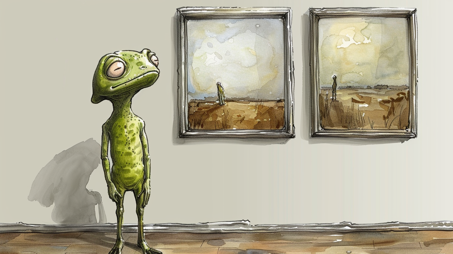
“Making Interactive Art: Set the Stage, Then Shut Up and Listen”
This article also resonates with me because it champions the idea that art is not just an artist’s expression but a dynamic interaction. The artist’s role shifts from being a narrator to a facilitator who sets up the environment and then steps back to let the audience interact and derive their own meanings. The author persuasively argues against the traditional view of art as a static expression, pointing out that interactive art should be more like a conversation or a performance that evolves. The analogy of the artist as a director who does not strictly dictate but rather guides actors (or participants, in this case) allows for a genuine, emergent experience. This perspective is enlightening as it underlines the shift from passive consumption to active engagement. I appreciate Igoe’s emphasis on the importance of simplicity and clarity in setting up interactive environments. The directive to “arrange the space” thoughtfully and to “remove anything extraneous” serves as a crucial guideline for creating an immersive and intuitive experience. This approach ensures that each participant’s interaction is meaningful and personal, rather than overshadowed by the artist’s own interpretations or expectations.
Moreover, the concept of listening to how people interact with the artwork—and the notion that these interactions might change over time—adds a layer of complexity to the creation and exhibition of interactive art. It suggests that the artwork is not complete upon its initial display but continues to evolve and resonate differently as people engage with it.