
Don’t Dim Your Light
Concept:
I wanted to work with LED lights and experiment with different objects to create a dimming effect. I was also inspired by lights and spotlights in general -ever since I was a kid but I also remember Professor Mang mentioning how lights work and function which made me think about it more because I always wondered the same thing too. For this project, I focused on creating a light setup that explores control and brightness through the use of a potentiometer (dial) and a push button. The user gets to decide when the light turns on and how bright it becomes. The idea connects back to choosing when to let your own light shine instead of dimming yourself for others.
Image: Link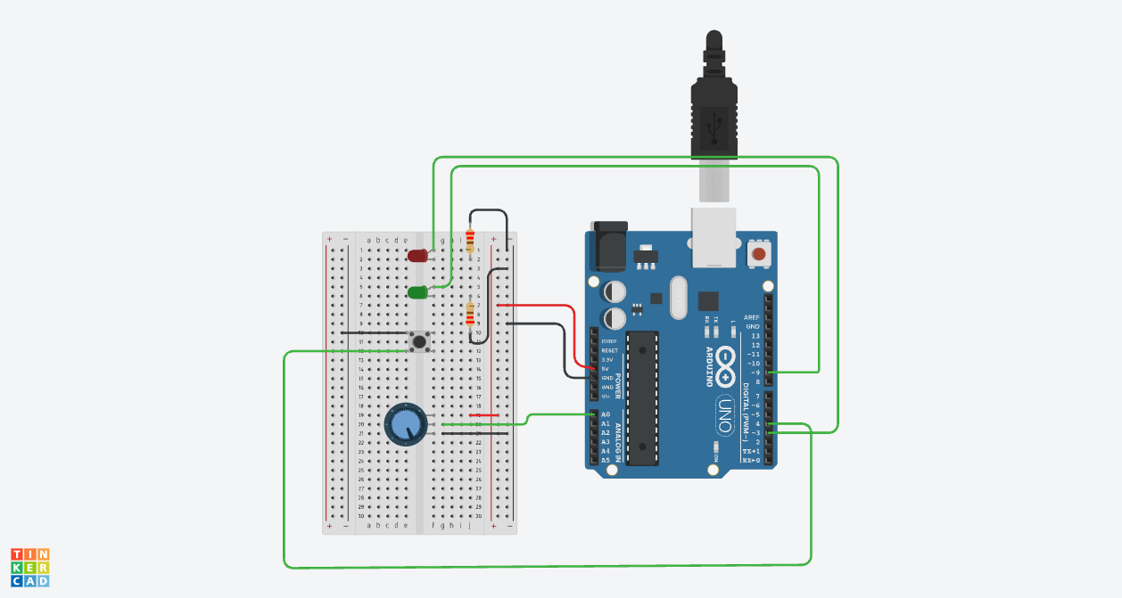
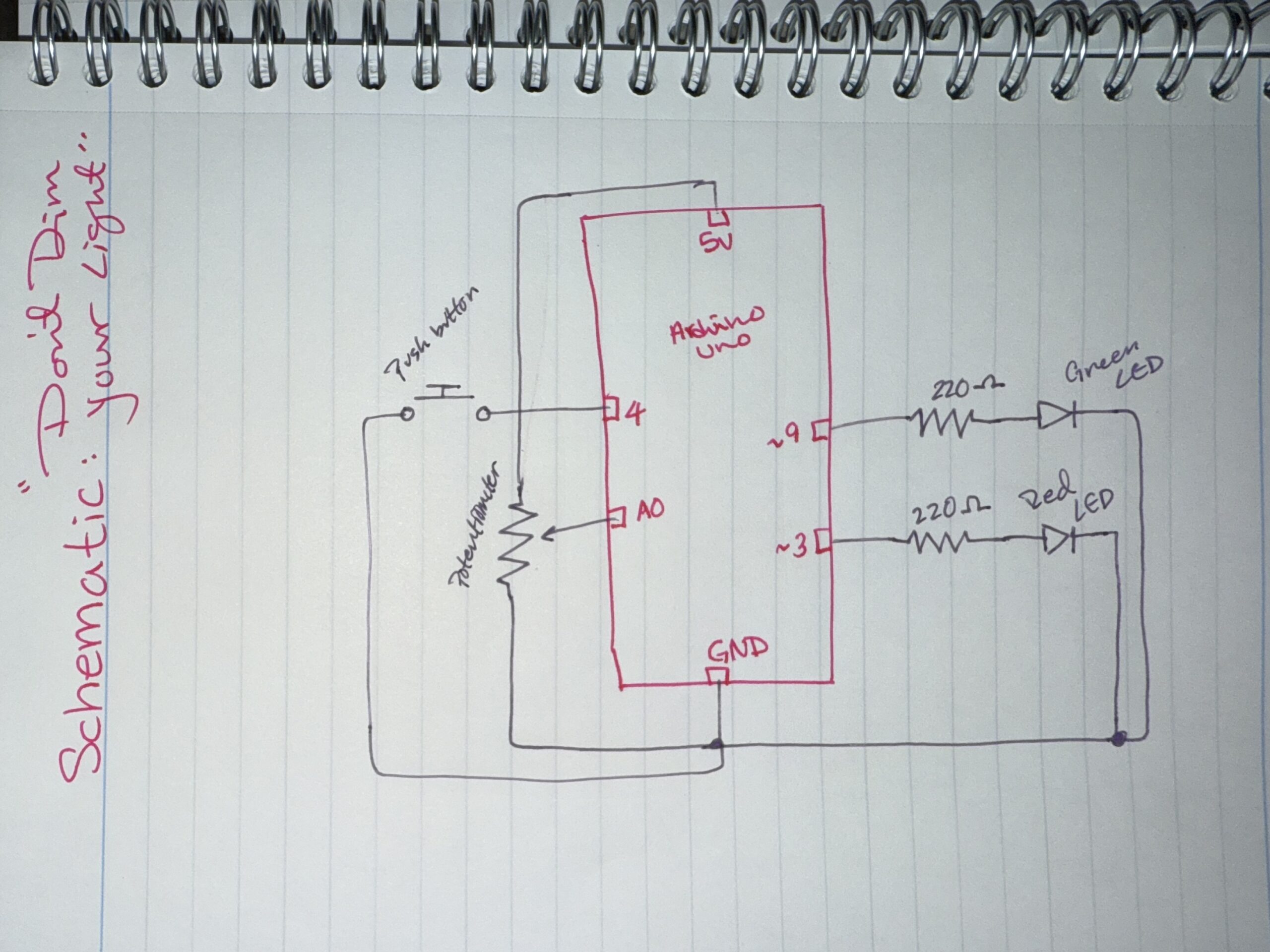
Hand-drawn schematic:
How this was made:
Setup: I started off by putting my resistors and LEDs on the breadboard and choosing the amount and colors of each which I used one red LED and one green LED with 220Ω resistors for both so I could protect the current and flow. After the LEDs were set and connected to Pins 3 and 9 so I could control their brightness, I focused on connected the push buttons and connecting the potentiometer to A0 and the push button to Pin 4. I also watched this video a while ago when we were first introduced to Tinkercad which I found was actually helpful: Tinkercad Circuit Diagram.
Code: While I was doing that, I also focused on the code, which surprisingly was the easiest part. I learned how to use analogRead() to read the potentiometer values and understand the overall idea of how to use the kit. I found out that the potentiometer gives values from 0 to around 1023, but the LED brightness only goes from 0–255 which is why I divided the value by 4 so the brightness would match correctly. For the [INPUT_PULLUP] code, I looked at this example (https://www.tinkercad.com/things/gfxVutEZ1QQ-inputpullup-example), which helped me learn and understand how to use the push button with the code. It made things easier because I didn’t need an extra resistor for the button since the code uses the Arduino’s built-in pull-up resistor.
full code
// C++ code
//
void setup()
{
  pinMode(3, OUTPUT); //the button pin for Red LED
  pinMode(9, OUTPUT); //the button pin for Green LED
  pinMode(4, INPUT_PULLUP); //the pushbutton to make it easy to wire
}

void loop() //for when the button is pressed
{
  int dialValue = analogRead(A0); //to read the dial
  int brightness = dialValue /4; //make the green light match

  if(digitalRead(4) == LOW) {
  analogWrite(9,brightness); //light brightness -green
  analogWrite(3,brightness); //light brightness -red
  } else {
    digitalWrite(3, LOW); //button will be off if not pressed
    digitalWrite(9, LOW); //button will be off if not pressed
  }

  delay(10); //Wait for 10 millisecond(s)
}
The hardest part out of all this was definitely the schematic. For some reason as a visual person I found this so confusing. I think because I’m used to thinking first, during, and after, the schematic required me to think and “brain dump” during the process, which is something I don’t usually do which is why I referred back to some Zoom call recordings and Collin’s Lab: Schematics. I also used an image of “cheat codes” to help me with the symbols since they’re different from the actual circuit.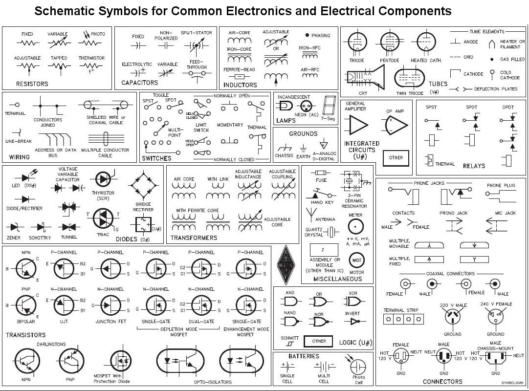
Overall, I did look at some research before experimenting by myself because its our first time doing this I didn’t want to mess anything up so I practiced, did some tutorials, looked over examples before I did my final work. I watched videos about each part I wanted to work with, like the buttons (Pushbutton Digital Input With Arduino in Tinkercad) and also the potentiometer (TinkerCad Potentiometer with LED).
Reflection:
Making the schematic was honestly the hardest part because it forced me to understand the circuit as a system instead of just colored wires connected together. At first I found it really confusing but I actually started to like writing schematics because they helped me understand Arduino better and made me understand my own project more clearly. For future improvements, I would like to make the LEDs react differently instead of both doing the same thing? so maybe one LED could fade in while a few others fade out, or I could add sound so the project feels more interactive and creates more of a sensory experience.