
Exercise 1:
P5 code:
https://editor.p5js.org/farahshaer/sketches/K1ETNJevI
Arduino code:
Process:
So for the first part, it was a one way communication between arduino and p5 with the idea of taking an input from a sensor on arduino and using that data to control the circle on p5. I used a potentiometer as my sensor because it gives a smooth range of values which makes it easier to control the movement on the screen. The arduino reads the values and sends it to p5 using serial.prin1n(). Then in p5 I used readUntil(“\n”) to receive the data and once I got that value I cleaned it using trim() and converted it into a number using int(). Then I map it from the sensor range to the width of the canvas so it can control the x position of the ellipse. As I turn the potentiometer, the circle moves left and right on the screen.
Exercise 2:
P5 Code:
https://editor.p5js.org/MariamAlameri/sketches/oWfNkocIc
Arduino Code:
Process:
The second exercise involved bidirectional communication between p5 and Arduino, where we were asked to control the Arduino from p5. I wanted to create a p5 sketch that allows the user to control the brightness of an LED on the Arduino board. I chose to use a slider in the sketch, as it provides an intuitive and suitable way to adjust brightness. I also referred to the exercises completed in class and adjusted them to meet the purpose of this assignment. In the Arduino code, I used two if statements to ensure that the LED responds when data is received from p5, and to constrain the brightness value within the range of 0–255 for proper PWM control. In the p5 sketch, I implemented the slider using createSlider, adjusted its position and appearance, and used port.write to send the brightness value to the Arduino, allowing accurate control of the LED.
Exercise 3:
Concept:
After completing the first two exercises and creating communication between the p5 sketch and the Arduino code and board back and forth, in this exercise we had to combine both. When the ball in the p5 sketch bounces on the ground, the LED on the board flashes on and off, and when we use the potentiometer, which is the analog sensor on our Arduino board, we control the wind in the sketch and move the ball left and right.
P5 Code:
https://editor.p5js.org/farahshaer/sketches/hAwlRZjXM
Arduino Code:
Demonstration:
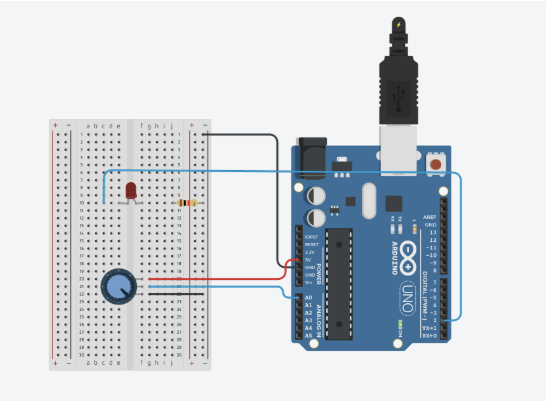
Circuit:
Schematic: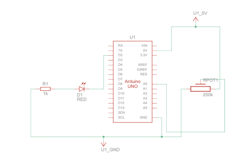
Code we’re proud of:
One part of the code that we are proud of is the bounce detection and how it connects to the Arduino:
//the bounce detection
  if (position.y > height - mass / 2) {
    //check if the ball hits the ground
    velocity.y *= -0.9; // A little dampening when hitting the bottom (reverse the direction when it hits)
    position.y = height - mass / 2; //keep it above the floor
    bounce = 1; //to mark that the bounce happened
  }
  //send to arduino
  let sendToArduino = bounce + "\n"; //send the bounce value 1 or 0 and the "\n" tells ardunio the message is done
  port.write(sendToArduino);
  // reset bounceafter it sends
  bounce = 0;
}
We are proud of this part because it turns the ball bouncing into a signal that affects something physical (the LED). It also only sends the signal once per bounce, which makes the interaction feel more intentional instead of constant.
Process:
So in this version of the gravity and wind example, I added serial communication so the sketch can interact with an Arduino on p5. Instead of controlling the wind using the keyboard like in the original example, the wind now comes from an analog sensor (like a potentiometer) connected to the Arduino. The Arduino sends that sensor value to p5, and I map it to a wind force so it pushes the ball left or right. I also added a bounce signal that goes the other way. Every time the ball hits the bottom of the canvas, I set a variable to 1 and send it to the Arduino. This tells the Arduino to briefly turn on an LED, then it gets reset back to 0 so the signal only happens once per bounce. Most of the original physics code stayed the same, but the main changes were adding serial setup, reading sensor data to control wind, and sending a bounce message back to control the LED.
For the Arduino side, I worked on the Arduino code to align with the p5 sketch we have and create serial communication from the Arduino board to the p5 sketch and vice versa. I set it up so the Arduino sends the analog sensor value from A0 to control the wind on the ball on the sketch, and receives a bounce signal from p5 when the ball hits the ground. When this signal is received, the Arduino briefly turns on an LED to indicate the bounce, and then resets the value so the LED only activates once every time it touches the ground. I also made sure the serial communication was properly structured so both inputs and outputs work smoothly together at the same time, allowing interaction between the physical sensor and the digital sketch.
Reflection:
This exercise helped us understand how bidirectional communication actually works, instead of just sending data one way. It was interesting to see how the Arduino and p5 sketch can influence each other at the same time. One challenge we ran into was getting the potentiometer to properly control the wind. Even though the LED response worked, the sensor input was inconsistent, which made it harder to debug whether the issue was in the Arduino code or the p5 code. This made us realize how important timing and serial communication structure are, especially when both sides are sending and receiving data continuously.
If we had more time, we would focus on possibly smoothing the wind movement so it feels less jumpy. We would also experiment with adding more physical outputs, like multiple LEDs or different types of sensors, to make the interaction more dynamic but we just wanted to stick with the assignment instructions for now to get a grasp of the concept.