
My concept:
For this week’s assignment, I worked on a small circuit that uses a button and a potentiometer to control two LEDs. The button works as a digital input, so the LED connected to it only turns fully on or fully off. The potentiometer is an analog input, so it gives a range of values, and that lets the second LED fade smoothly instead of switching instantly. Seeing both of them together helped me understand the difference between digital and analog in a very clear way. One is fixed, and the other changes gradually.
Code Snippet I’m Proud Of:
int potValue = analogRead(potPin);
int brightness = potValue / 4;
analogWrite(fadeLed, brightness);
This part made the most sense to me once I understood what PWM actually does just like how i learned on the slides. The potentiometer gives a value from 0 to 1023, but the LED only uses 0 to 255. When I saw the LED fade smoothly as I turned the knob, it finally clicked for me how analog control works.
Process
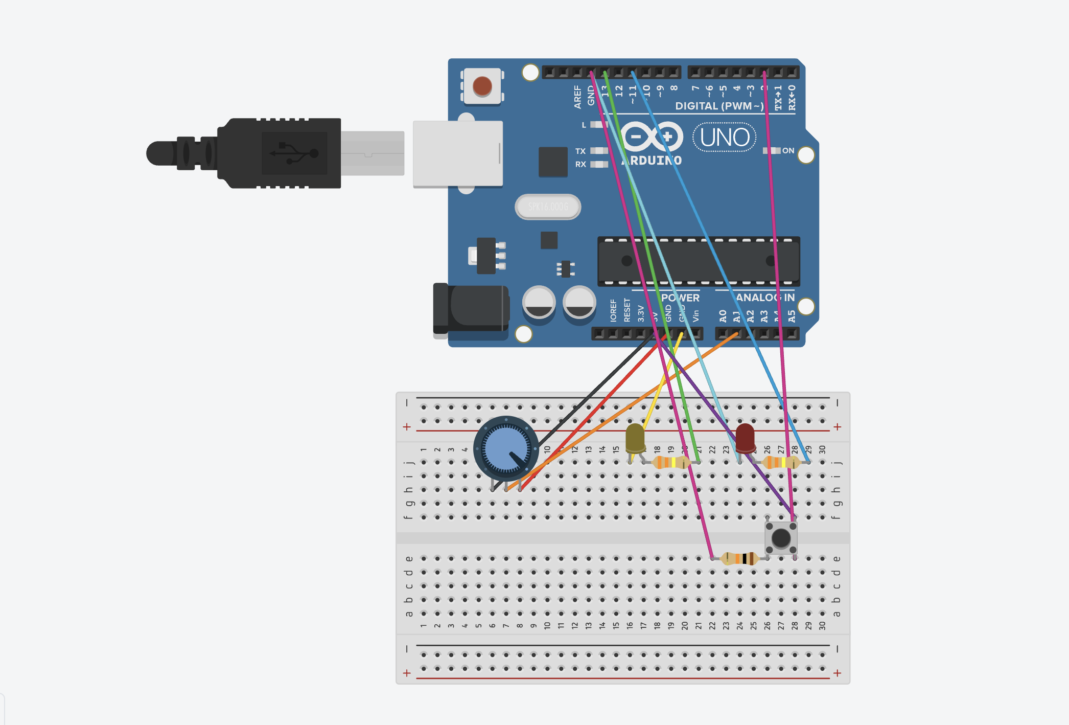
I started this assignment by deciding which inputs and outputs I wanted to use. Since the goal was to work with both analog and digital inputs, I chose a pushbutton for the digital part and a potentiometer for the analog part. I wanted each one to control a different LED so I could clearly see the difference between the two types of signals.
I began by setting up the breadboard and making sure it had power. I connected the 5V pin from the Arduino to the positive rail and the GND pin to the negative rail. After that, I wired the button to pin 2 and added the 10k resistor to ground so it could work as a pull‑down. Then I connected the potentiometer to A1 and made sure the middle pin was going to the analog input. Once both inputs were connected, I added the two LEDs with 330 resistors to protect them.
At first, I tried to test everything on the physical Arduino, but the board started acting in a way that it wasn’t working and connecting to the laptop and kept shutting down, the green light would blink for a second and then everything will go off, and I wasn’t able to find the cable option on the ports shown to connect the code with my arduino, so that’s why it wasn’t working. After a lot of troubleshooting, I realized the problem was not my code or my wiring. The board itself was not responding properly. Because of that, I moved the project to Tinkercad so I could finish the assignment without dealing with hardware issues I could not fix. In Tinkercad, the circuit worked the way it was supposed to, and it helped me understand the logic more clearly.
My tinkercad:
Sketch: 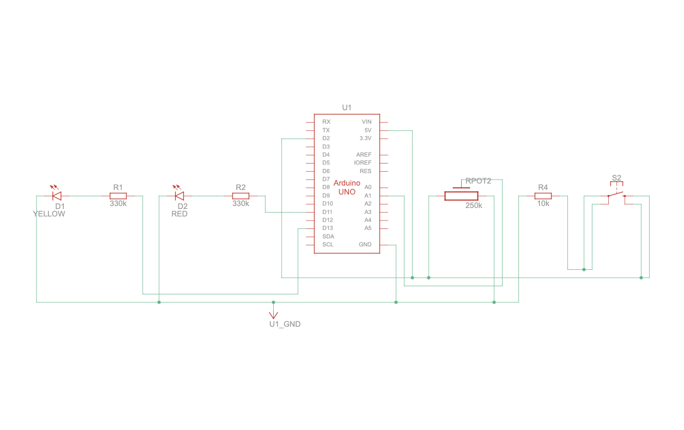
My circuit:
My code:
int buttonPin = 2;     // the button
int ledPin = 13;       // the digital LED
int fadeLed = 11;      // the fading LED
int potPin = A1;       // the potentiometer

int buttonState = 0;   // to store what the button is reading
int potValue = 0;      // to store what the potentiometer is reading
int brightness = 0;    // to store LED brightness

// pinMode( tells the Arduino how each pin will be used)
void setup() {
  pinMode(buttonPin, INPUT); //the button is an INPUT because I’m reading from it
  pinMode(ledPin, OUTPUT); // the LEDs are OUTPUTS because the Arduino controls them
  pinMode(fadeLed, OUTPUT); //this runs once when the Arduino starts
}

void loop() {

  buttonState = digitalRead(buttonPin); // this checks if the button is pressed or not, t will be HIGH when pressed and LOW when not pressed


// if the button is pressed this means the LED on pin 13 turns on
// if the button is not pressed this means LED turns off

This is a simple if/else condition.
  if (buttonState == HIGH) {
    digitalWrite(ledPin, HIGH);
  } else {
    digitalWrite(ledPin, LOW);
  }

  // the pot gives a value between 0 and 1023
// this depends on how much I turn the knob

// I store it in potValue so I can use it for brightness
  potValue = analogRead(potPin);

  //analogWrite() only accepts values from 0 to 255 so dividing by 4 converts the 0–1023 range into 0–255
  brightness = potValue / 4;

//this sends a PWM signal to pin 11,the LED brightness changes smoothly based on the pot
// the higher pot value means brighter LED
  analogWrite(fadeLed, brightness);
}
Reflection / Future
This project helped me understand analog and digital inputs in a more real way. I already knew the definitions, but seeing how each LED reacted made it easier to get it. The digital input was very straightforward because the LED only turned on or off. The analog input felt more interesting because the brightness changed slowly when I turned the potentiometer. Using both at the same time made me feel more comfortable with how the Arduino reads different signals.
I also learned a lot about wiring and how small mistakes can mess up the whole circuit. I kept running into problems on the breadboard, and even when the wiring looked right, things still didn’t work. When the physical board stopped responding completely, I had to switch to Tinkercad. Even though that was frustrating, it helped me focus on the logic instead of fighting with hardware issues. It also showed me how important it is to check every connection carefully.
In the future, I want to try using more sensors and making the interactions more interesting. I also want to keep my wiring cleaner because it makes debugging so much easier. Now that I understand the basics better, I feel more ready to try bigger projects and see how these components can work together in different ways.