
 Github link
https://github.com/MouzaAlMheiri/Intro-to-IM/blob/main/Week%209-%20Digital%20and%20Analog
Concept:
For this project, I knew I wanted to combine what we learned in class with something I could build on myself. I decided to use a light sensor to control one of the LEDs and a switch to control the other LED. This allowed me to explore both types of input in one system.
The interaction is split into two parts. One LED is controlled digitally using the switch, meaning it turns fully on or off. The second LED is controlled using the light sensor, where its brightness changes depending on the amount of light detected. This means one LED is controlled digitally, while the other is controlled in an analog way.
By combining both digital and analog inputs in the same project, I was able to create a system that shows the difference between these two types of control
Code Im proud of:
 // if statment so that the LED can be controlled digitally by switch
 if (switchState == LOW) {
   digitalWrite(digitalLED, HIGH);
 } else {
   digitalWrite(digitalLED, LOW);
 }

 // read light sensor
 sensorValue = analogRead(ldrPin);
 Serial.println(sensorValue);

 // keep readings in my range
 sensorValue = constrain(sensorValue, 330, 650);

//when its reads the light if its dark the LED will be bright and light the LED will be dimmer
 brightness = map(sensorValue, 330, 650, 255, 0);

 // sets the analog LED brightness
 analogWrite(analogLED, brightness);
The part of the code I am most proud of is the section where I used the if statement together with the light sensor readings to control the LEDs. In this part, I was able to combine both digital and analog inputs in one system.
I used the if statement to control the digital LED based on the switch input, which helped me understand how conditional logic works in Arduino. At the same time, I used analogRead () to read values from the light sensor and store them in a variable. I then applied constrain () to keep the readings within a specific range, and used map () to convert those values into brightness levels for the LED.
This allowed me to control the second LED in an analog way, where its brightness changes depending on the light in the environment. This part of the code reflects what we learned in class, but I was able to apply it on my own and integrate it into a larger system. I am proud of this because I was able to understand how the sensor values translate into output and use that to create a smooth and responsive interaction.
Process :
I first began by deciding what I wanted to include, which I knew was a light sensor and a switch. I wanted to make sure I was using both types of inputs that we learned in class.
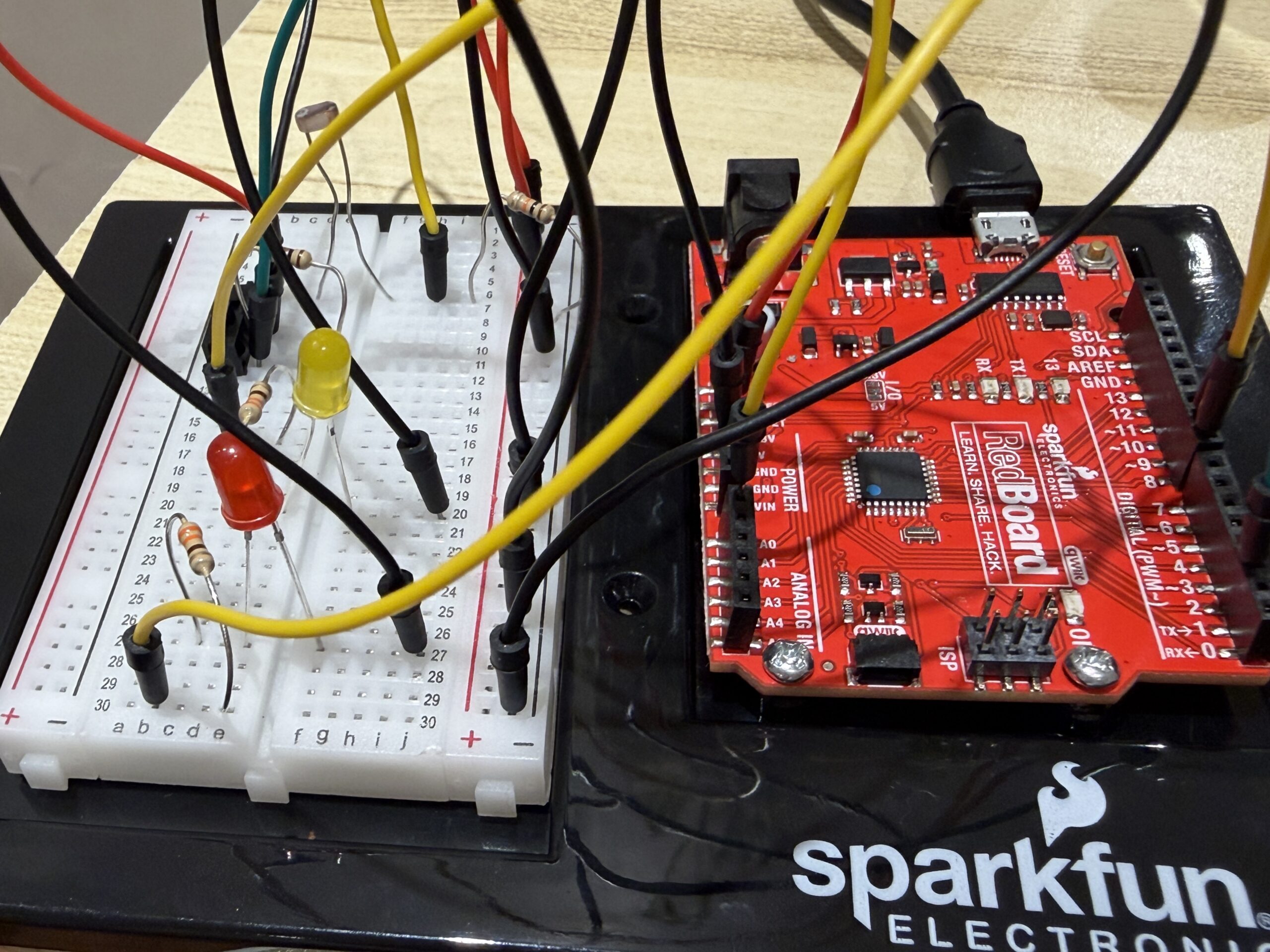
I then started by setting up my breadboard and making sure it had power. I connected 5V from the Arduino to the positive rail on the breadboard, and then connected a black wire from GND to the negative rail to complete the circuit.
After that, I began building the circuit itself. I started with the light sensor, making sure it was connected to the analog pin AO.I added a 10k resistor to create the voltage divider, and then added a wire to connect it to power.
Next, I connected the switch. I made sure it was connected to a digital pin on the Arduino, and I added a black wire from the switch to ground so that it could complete the circuit when activated.
Finally, I added the two LEDs. Each LED was connected with a 330 resistor to protect it. At this point, the full circuit was complete, with the light sensor controlling one LED and the switch controlling the other.
Reflection/ Future:
This project helped me better understand how to use different parts of the Arduino Uno board, especially the difference between digital and analog pins. I was able to use both types in one system, which is something I think will be very useful in future work. It made me more confident in connecting components and understanding how the hardware and code work together.
I also learned how different types of inputs can create different kinds of interactions. The digital input was simple and direct, while the analog input required more thinking and allowed for more gradual control. This helped me see how I can design more dynamic and responsive systems in the future.
In future projects, I would like to experiment with combining more sensors or creating more complex interactions between inputs and outputs. I also want to explore how I can make the system more interactive or meaningful, possibly by connecting it to a real world use case or adding more complexity to the design.
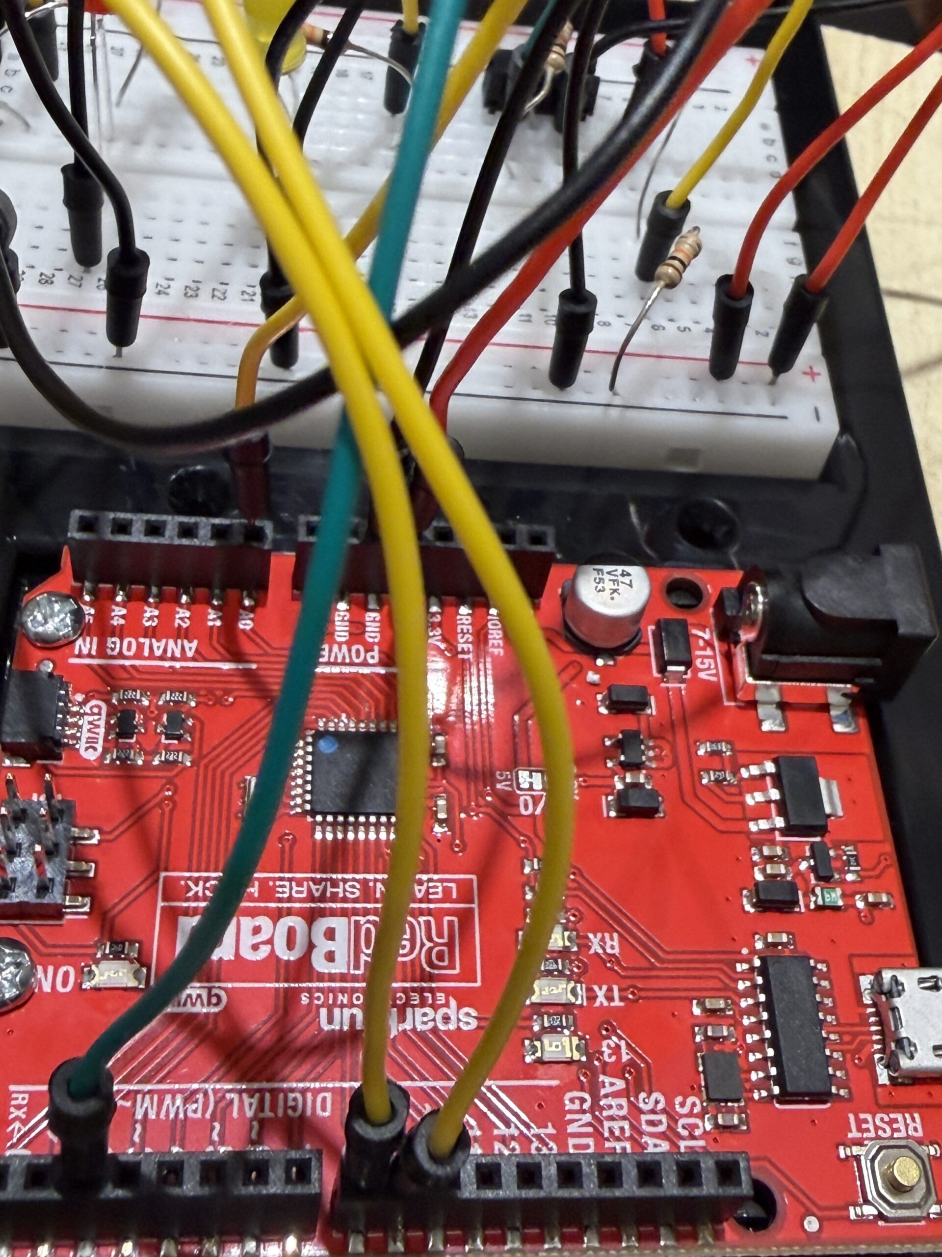
Photos:
Video:
https://vimeo.com/1188360854?share=copy&fl=sv&fe=ci
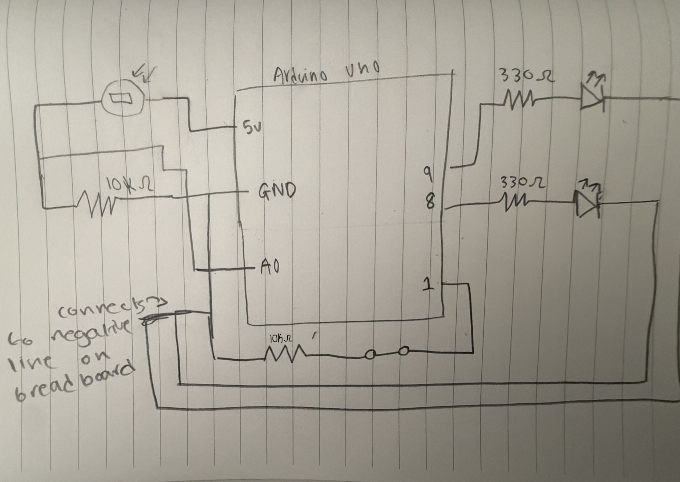
Drawn circuit
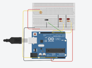
 Digitalcircuit
:
Refrences:
https://electronicsclub.info/circuitsymbols.htm
https://www.pcbasic.com/blog/led_symbol.html