
Concept:
Something I adore doing for fun is solving escape rooms with friends. While my escape/loss ratio is good enough😉, I was inspired a lot by the locks I see in escape rooms. My favorite part of the escape rooms is when you solve the puzzles and go to the next room by unlocking the lock. Usually you find a string of numbers from a different puzzle and then twist the lock to unlock it. But I wanted to flip the concept, and try by twisting the dials, to find the combination and enter it in to “escape”. So that’s how my idea came about pretty much haha.
Implementation:
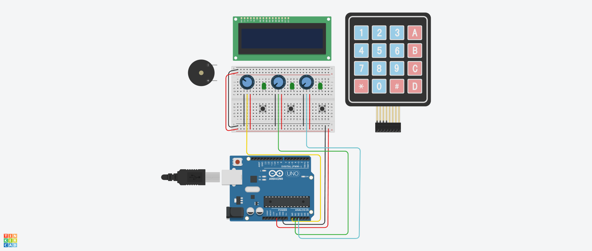
The project will be completely done in Tinkercad and will utilize a few old things that we’ve seen on class but also a few new things I wanted to try out.
The way how the game would work is, each Potentiometer will act as a lock you can twist around (from this point, I’ll refer to the Potentiometers as ‘locks’).
Each lock will have a value you have to get. Now on the LCD Display I’ll have the current value that the user is twisting displayed. Then once the user twists to the right value, the Piezo will make a beep. But for the value to be correct and locked in, the user needs to twist it, listen to the sound and press the button. If the value is correct, then the LED will light up and that same value will be displayed on the screen.
From what I’ve researched, the Potentiometer can have values from 0 to 1023. But on Tinkercad, there’s an array of values that can be inputted only with mouse input.
Those values are: 0, 20, 41, 61, 82, 102, 123, 143, 164, 184, 205, 225 and so on…
Each lock will have a different value from this array of integers. When the correct value is guessed (by virtue of the LED lighting up), it will be displayed on screen. Most likely I’d do something like:
Lock 1: *the value of Lock 1*, Lock 2: *the value of Lock 2* and Lock 3: *the value of Lock 3*
After all three values have been guessed, then the user will input them on the keypad. When all three values have been entered, then a victory sound will be played by the Piezo.
Challenging parts to the Project:
I would say the most challenging part of the project is definitely understanding how to use the LCD screen and also the Keypad. I’ve not tested or played with them before but I can mitigate this by looking up the reference sheet for each Arduino part. Alongside this, I can use videos that explain these parts so I can understand how they work, but mostly so I can see how to code for them is written.
I think overall this will be a fun project to go with and experiment with these new parts in Tinkercad. Hopefully something interesting as like a minigame can come off from it.
This looks like a great project! For dealing with the “steps” in the simulated potentiometer what I recommend is to decide on a fixed number of divisions for the code and then map the potentiometer value into that range. For example you could decide that each digit in the code can be a value from 0 to 9, so a code could be 0-2-4, 9-1-3, etc. Have a look at the “map” function and experiment with mapping the potentiometer value to 0..9 value.
The real potentiometer value will jump around a little due to noise so that’s another reason you shouldn’t make the value mapping fixed but rather accept a range. If you provide the user feedback on what number they currently have selected in real-time it will make it a lot easier for the user to understand what’s going on. Looks like a good idea, go for it!