
Due to the time crunch this week, I wanted to make something small which I would be able to achieve on time, so unfortunately, this won’t be as fun as usual. (߹ ᯅ ߹)
Concept:
I thought I’d make a Mood Light with a Panic Button: the potentiometer (analog) controls a blue LED that fades smoothly, while a pushbutton (digital) triggers a red LED to blink rapidly, like an alert. I liked the contrast between the two, and I thought it would be fun to see if I could make it work. It kind of reminds me of an Ambulance, maybe.
Process:
Due to my wonderful wi-fi here, my internet kept disconnecting in class, so if there is content here that WAS covered in class but I struggled with, I’m assuming those were what were mentioned while I was fighting with the wi-fi and my data (sorry!). The first thing I had to understand was the pull-down resistor on the button. I kept seeing it in tutorials without really knowing what it was for, so I looked into it. I found that if I just wire a button between 5V and a digital pin, the pin has no defined state when the button isn’t pressed. It floats and picks up random electrical noise, which makes it read random HIGH and LOW values. A pull-down resistor (10k ohms in my case) connects the pin to GND through a high resistance, so when the button isn’t pressed, the pin reads LOW. When the button is pressed, it connects to 5V to show HIGH.
The rest of the circuit was pretty straightforward. In the beginning, I kept forgetting which was the cathode and anode in the LEDs and I had some issues with figuring out the wires (silly mistakes and TinkerCad creating wires when I wanted to click on something else).
The analog part reads the potentiometer using analogRead(), which returns a value between 0 and 1023. Since it expects a value between 0 and 255, I divide the reading by 4 to scale it to the right range. The digital part reads the button with digitalRead(), and if it’s HIGH (pressed), the blue LED alternates on and off with a short delay.
const int POT_PIN    = A0;
const int BUTTON_PIN = 2;
const int FADE_LED   = 9; //analog
const int BLINK_LED  = 8; // digital

void setup() {
  pinMode(BUTTON_PIN, INPUT);
  pinMode(FADE_LED, OUTPUT);
  pinMode(BLINK_LED, OUTPUT);
  Serial.begin(9600);
}

void loop() {
  // Analog, potentiometer controls fade LED brightness
  int potValue = analogRead(POT_PIN);
  int brightness = potValue / 4;       // 0–1023 → 0–255
  analogWrite(FADE_LED, brightness);

  // Digital, button triggers blink LED
  int buttonState = digitalRead(BUTTON_PIN);
  if (buttonState == HIGH) {
    digitalWrite(BLINK_LED, HIGH);
    delay(100);
    digitalWrite(BLINK_LED, LOW);
    delay(100);
  } else {
    digitalWrite(BLINK_LED, LOW);
  }

  Serial.print("Pot: "); Serial.print(potValue);
  Serial.print("  Button: "); Serial.println(buttonState);
}
One thing I initially got wrong: I had the fade LED on pin 7 and couldn’t figure out why it was only turning fully on or fully off with no in-between. Pin 7 doesn’t support PWM, and only pins with the ~ symbol can use analogWrite(), so I moved it to pin 9 and it started working. Good to know.
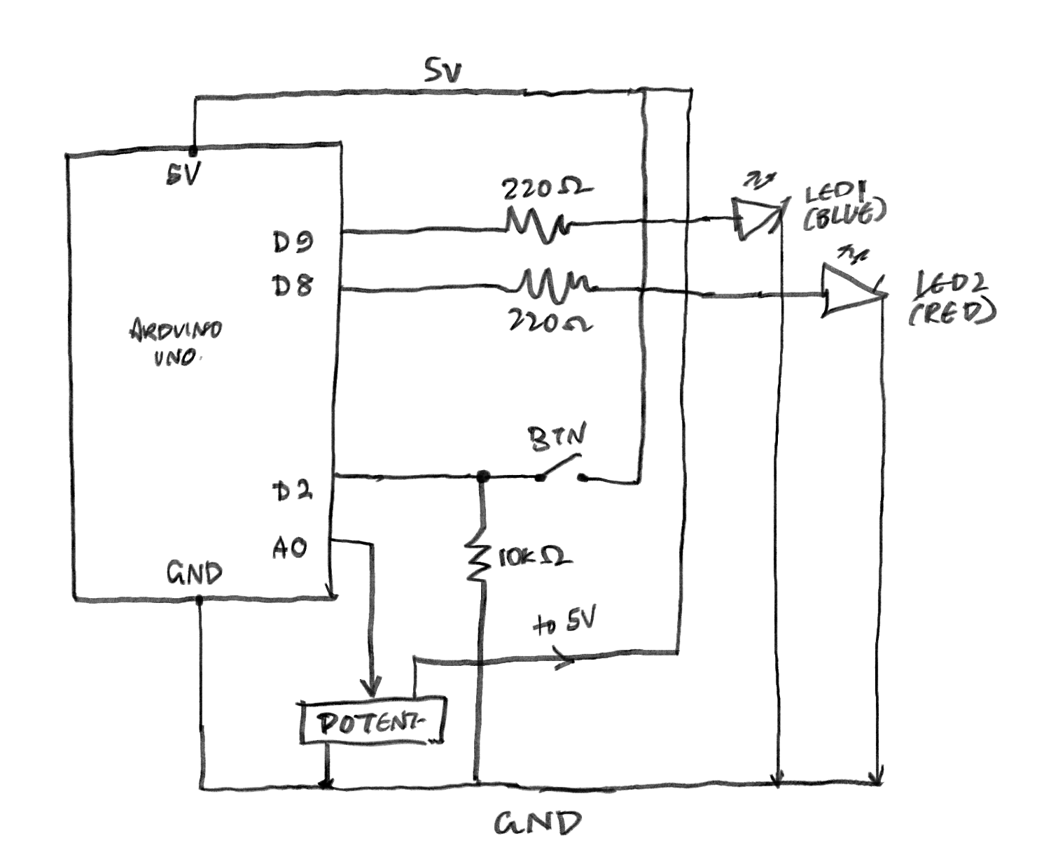
Schematic:
I don’t even know if this is right, so if it’s not, I am so sorry. I tried to look at class diagrams and went ?, so then I looked at TinkerCad’s schematic and went even more ???.
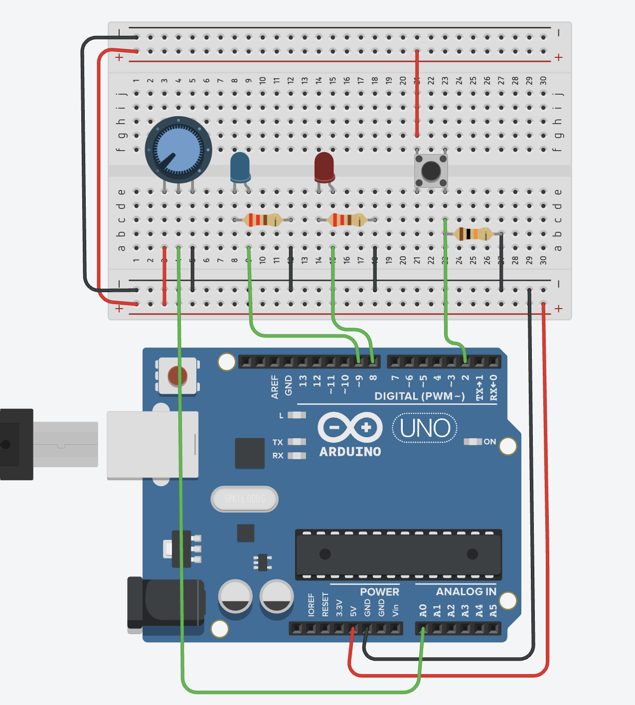
Circuit:
Reflection/Improvements:
- Right now, the buttons just trigger one fixed blink pattern. It would be more interesting to have it cycle through different patterns on each press (slow blink, fast blink, heartbeat, etc.) using a counter variable. That would also give the panic button more character.
- Next time, I’d want to do something much more ambitious. As long as I figure out the beginning things, I can try to make cooler projects with this. I do want to explore actions that aren’t just “a person pressing a thing” to make things interesting.
- (I can’t wait to get my physical Arduino kit so I can try to make this IRL! (≧▽≦))
Your schematic is pretty good but have a look at the symbols for LEDs and potentiometers here: https://learn.sparkfun.com/tutorials/how-to-read-a-schematic/all
Also you mean 330ohm resistors, not 220ohm and the “to 5V” isn’t necessary. Otherwise looking good.