Week 9: Analog and Digital Sensor

Concept:

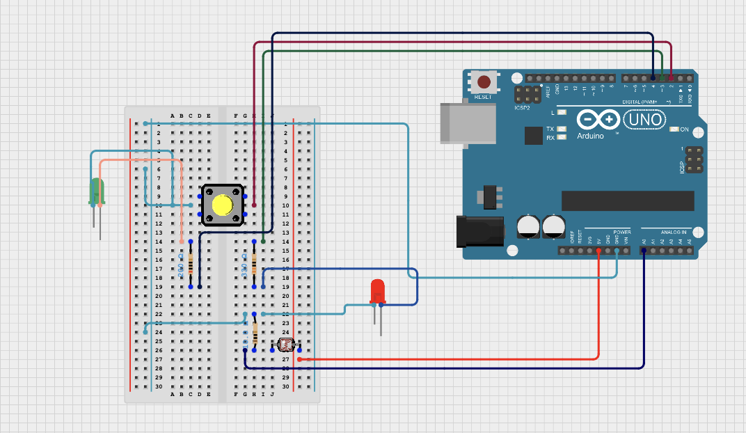
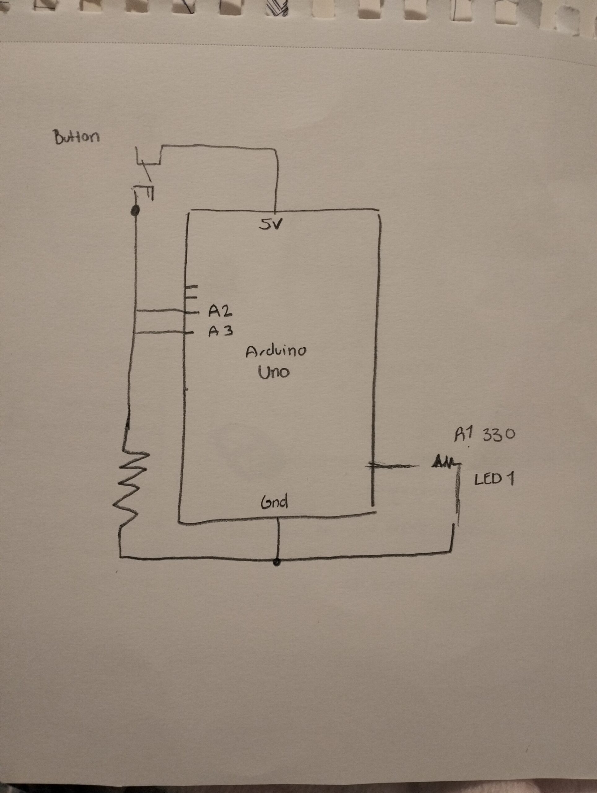
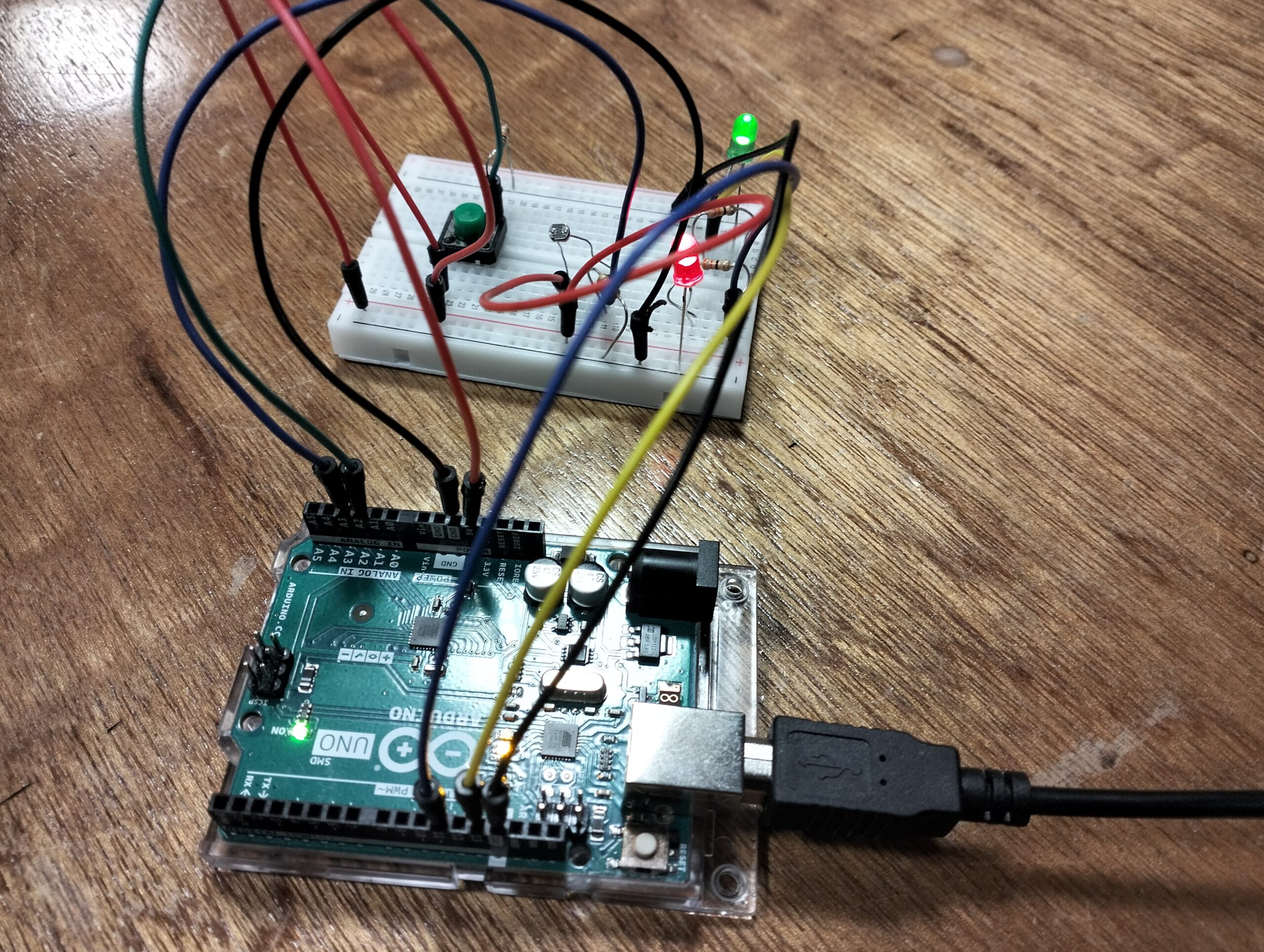
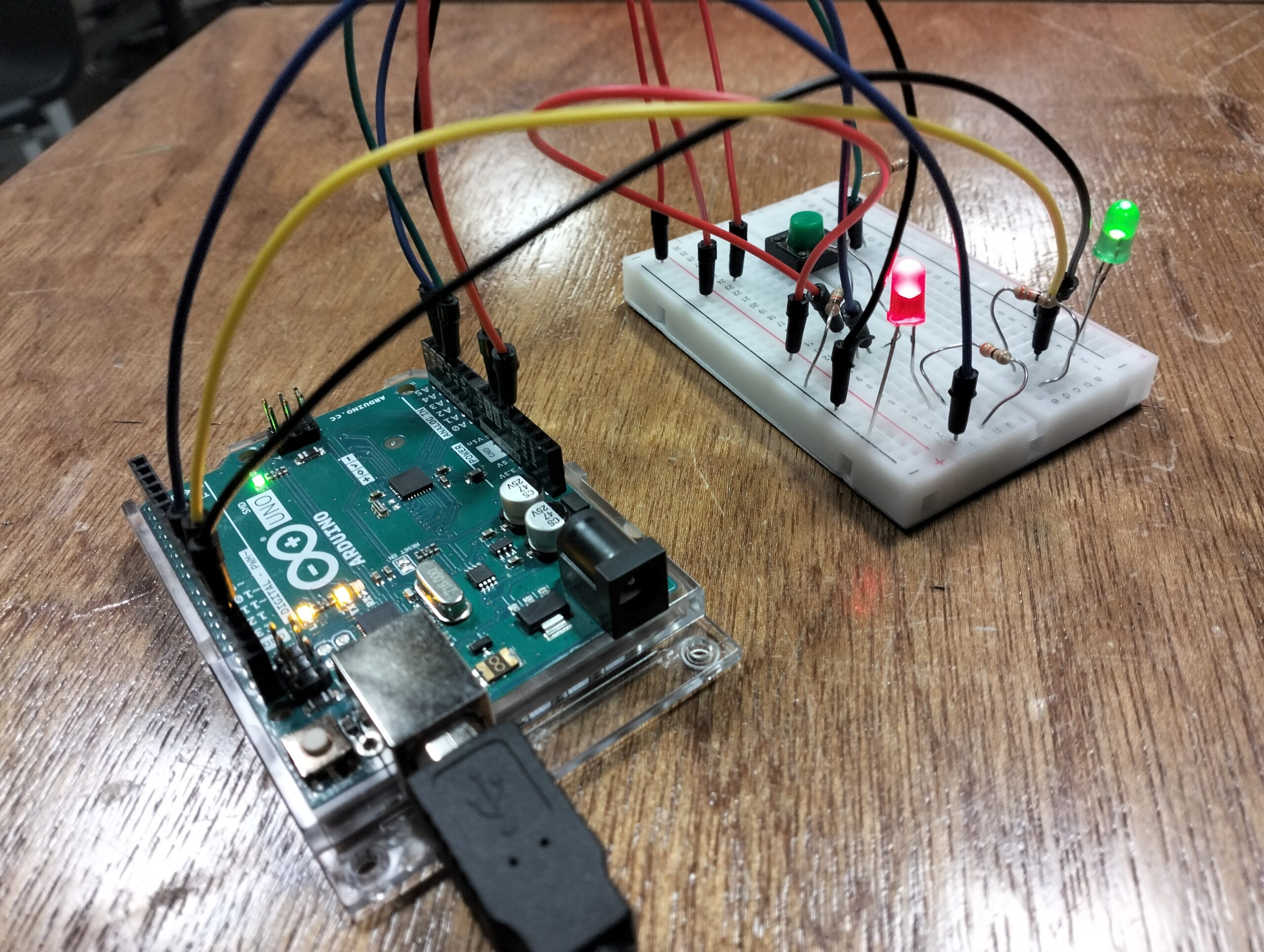
For this project, I decided to use one digital sensor and one analog sensor to control two LEDs. For the digital part, I connected a push button to a digital pin to control one LED — pressing the button turns the light on, and releasing it turns it off. For the analog part, I used a potentiometer connected to an analog input to control the brightness of a second LED through an analog output. As I turned the knob, the LED smoothly adjusted its brightness, demonstrating how analog signals can vary continuously instead of just turning on or off. This setup reflects the difference between digital and analog control and how both can work together in an interactive circuit.

Video Demonstration:

https://drive.google.com/file/d/1_urM0vEA__Piz7zGG_TUHDnuhy5QYUgQ/view?usp=drive_link

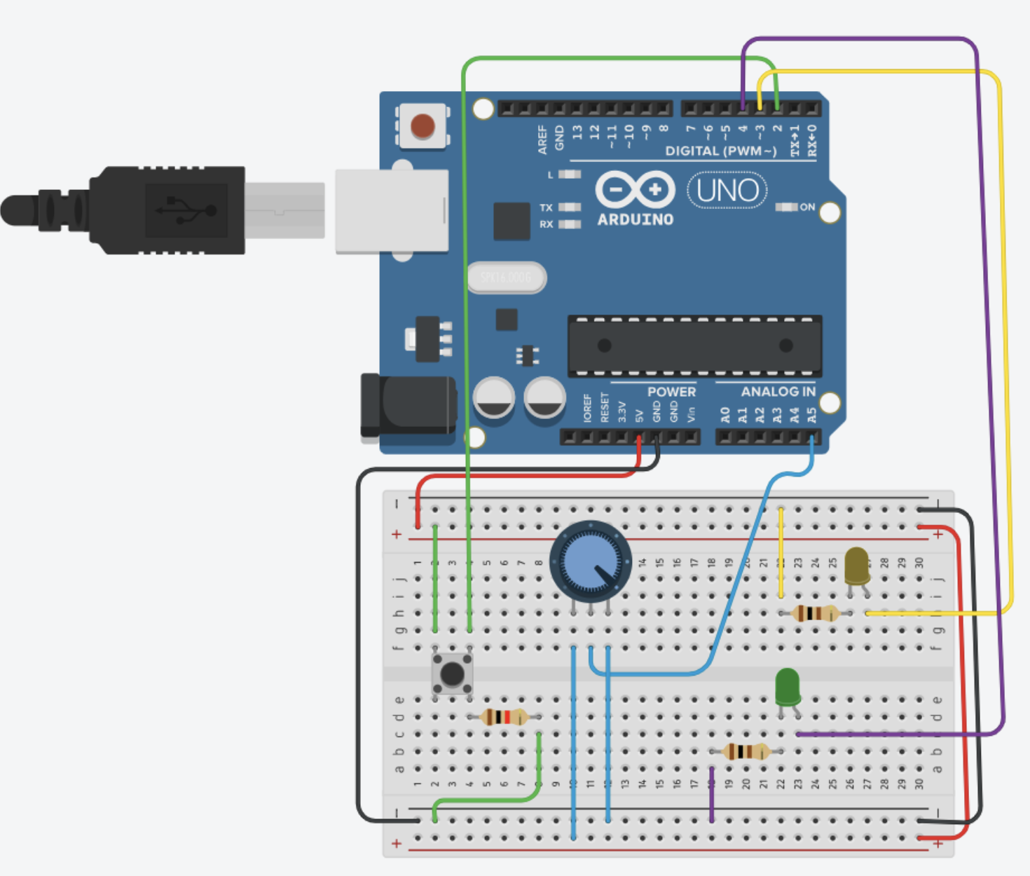
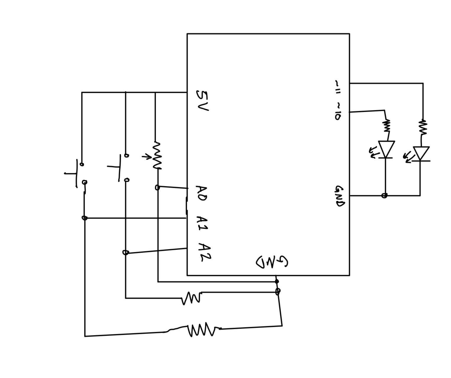
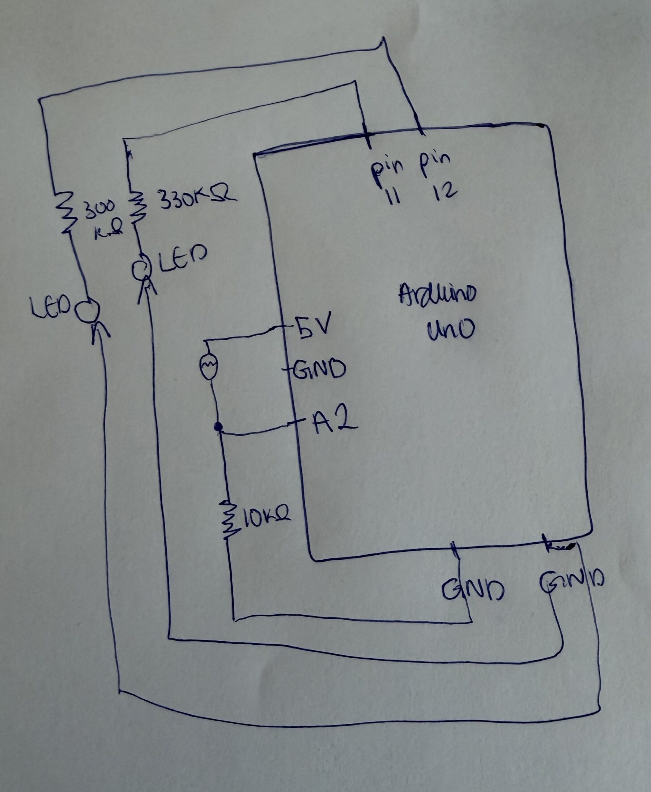
Circuit Illustration:

Code Highlight:

// Define pin numbers
int ledPin1 = 11;   // LED controlled by potentiometer (analog LED)
int ledPin2 = 2;    // LED controlled by button (digital LED)
int buttonPin = 7;  // push button input

void setup() {
  // Set pin modes
  pinMode(ledPin1, OUTPUT);     // pin 11 used for PWM (brightness control)
  pinMode(ledPin2, OUTPUT);     // pin 2 for digital on/off LED
  pinMode(buttonPin, INPUT);    // button as input (external resistor required)
  
  Serial.begin(9600);           // start serial monitor for debugging
}

void loop() {
  // Read the potentiometer (analog sensor)
  int sensorValue = analogRead(A1);     // reads values from 0–1023
  Serial.println(sensorValue);          // print the reading to serial monitor

  // Control the brightness of LED on pin 11
  // analogWrite expects a range 0–255, so divide by 4 to scale down
  analogWrite(ledPin1, sensorValue / 4);
  delay(30);                            // small delay to stabilize readings

  // Read the push button (digital sensor)
  int buttonState = digitalRead(buttonPin);   // reads HIGH or LOW

  // Control the digital LED based on button state
  if (buttonState == HIGH) {     // if button is pressed (connected to 5V)
    digitalWrite(ledPin2, HIGH); // turn LED on
  }
  else {                         // if button is not pressed (LOW)
    digitalWrite(ledPin2, LOW);  // turn LED off
  }
}

Github Link:

https://github.com/JaydenAkpalu/Intro-to-IM/blob/f43175106ae171c88a5c7db0410a56dc965127af/Week9_AnalogAndDigitalSensor.ino

Reflections & Future Improvements:

Working on this project helped me really understand the difference between digital and analog sensors and how they can control things like LEDs. I saw that a digital sensor, like a push button, only has two states — on or off — which makes it easy to control an LED directly. On the other hand, an analog sensor, like a potentiometer, can give a range of values, letting me gradually adjust the brightness of an LED. It was really satisfying to see how these two types of input behave so differently in a circuit.

If I were to improve the project, I’d try adding more interactive elements. For example, I could use multiple buttons or potentiometers to control more LEDs, or even combine the potentiometer with a light sensor so the LED responds to changes in the environment automatically. I’d also like to experiment with different LED effects, like fading, blinking patterns, or color changes, to make it more dynamic and fun. Overall, this project gave me a better understanding of how simple inputs can be used creatively to make interactive circuits.

Reflection- Week 9

When I read Physical Computing’s Greatest Hits and Misses and Making Interactive Art: Set the Stage, Then Shut Up and Listen, I started to think more deeply about what it really means to make something interactive. The first reading talked about how many beginner projects in physical computing repeat the same ideas, like using a sensor to make lights blink or to trigger sound. At first, I felt a little unsure because my own project also used simple tools like a light sensor and a button. But as I continued reading, I understood the real message: it’s okay to build something that has been done before, as long as I make it my own and give it a purpose. That made me feel more confident about my project. It reminded me that creativity doesn’t always mean doing something completely new, but doing something familiar in a meaningful or personal way.

The second reading focused on how interactive art should let people explore freely. It said that once we build something, we should “set the stage” and then step back, allowing others to interact with it in their own way. I really liked this idea because it made me think differently about my project. When I pressed the button or covered the light sensor, I realized that I was not just testing the circuit, I was actually engaging with it and discovering what it could do.

Both readings made me see that physical computing is not just about coding or wiring but it’s about creating an experience. It’s about giving people something they can explore and learn from on their own.

Analog Sensor

Concept

For this project, I used one analog sensor and one digital sensor (switch) to control two LED lights.

The analog sensor I used was a photoresistor (light sensor). It changes how much electricity passes through it depending on how bright the light in the room is. The Arduino reads this change and adjusts the brightness of one LED  when it’s dark, the LED gets brighter, and when it’s bright, the LED becomes dimmer.

For the digital sensor, I used a pushbutton connected to a digital pin. When I press the button, it turns the second LED on or off.

To make it different from what we did in class, I added a “night light” feature. When the photoresistor detects that the room is very dark, the button-controlled LED automatically turns on, like a small night light. When the light comes back, the button goes back to working normally.

This made my project more interactive and closer to how real sensors are used in everyday devices.

 Schematic of my circuit
It shows the Arduino connected to:

  • A photoresistor and 10 kΩ resistor forming a voltage divider to read light levels.

  • A pushbutton connected to a digital pin.

  • Two LEDs , one controlled by the light sensor and the other controlled by the button

Final Results

When I tested the circuit:

  • The first LED smoothly changed its brightness depending on how much light the photoresistor sensed.

  • The second LED turned on and off with the button as expected.

  • When the room got dark, the second LED automatically turned on, working like a night light.

It was a simple but satisfying project, and the extra feature made it stand out from the class example.

Video: video-url

Arduino Code

Part of Cold I am proud of

void loop() {
  // --- Read photoresistor ---
  int lightValue = analogRead(lightPin); // 0–1023
  int brightness = map(lightValue, 0, 1023, 255, 0);
  analogWrite(ledAnalog, brightness);

  // --- Button toggle ---
  if (digitalRead(buttonPin) == LOW) {
    ledState = !ledState;
    delay(200);
  }

  // --- Night light feature ---
  if (lightValue < 300) { // If it's dark, auto turn on LED
    digitalWrite(ledDigital, HIGH);
  } else {
    digitalWrite(ledDigital, ledState ? HIGH : LOW);
  }

  // --- Print readings ---
  Serial.print("Light: ");
  Serial.print(lightValue);
  Serial.print(" | Brightness: ");
  Serial.print(brightness);
  Serial.print(" | LED State: ");
  Serial.println(ledState ? "ON" : "OFF");

  delay(200);
}

Github url: Github

Challenges and Further Improvements

While I was able to make both the analog and digital sensors work, I struggled a bit with arranging all the wires and resistors neatly on the breadboard. It took a few tries to get everything connected correctly.

I also had to test different threshold numbers for the night light feature to decide when the LED should automatically turn on. Once I found the right value, it worked well.

For my next project, I want to try using other kinds of sensors, like sound or temperature sensors, and make the circuit respond in new ways. I’ll also practice reading the code line by line to understand how each part works better before adding new features.

Week 9: Analog sensor and Digital sensor

Concept

For this project, to create an analog sensor and one digital sensor (switch), and use this information to control at least two LEDs, I decided to make for the digital sensor a connection between a digital pin and a button to control one LED light. For the analog sensor I used the analog input and output to control the second LED light, turning it on and off depending on how much brightness the light sensor received.

Circuit Illustration
Figure 1

Final Results

oplus_0
oplus_0

VIDEO

Arduino code
oid loop() {

int sensorValue = analogRead(A3);
Serial.println(sensorValue);
// set the brightness of pin 11
sensorValue = constrain(sensorValue,500,900);
brightness = map(sensorValue, 500, 900, 0, 255);
analogWrite(11,sensorValue);
delay(30);


  int buttonState = digitalRead (A2);
  if (buttonState == HIGH){
    digitalWrite(13,LOW);
  } else{
      digitalWrite(13,HIGH);
  }

Although it isn’t the most creative or unique code, I was happy to find that my initial code was working to make both LED lights light up, and it was just a matter of adding information for the sensorValue and the brightness to make the LED light responding to the light sensor to show a greater difference in the changes of brightness.

Github

https://github.com/imh9299-sudo/Intro-to-IM.git

Challenges and Further Improvements

While I was able to successfully complete the assignment and create both digital and analog responses, I wish I could have found a more creative way of obtaining these responses. Moreover, I struggled to put the code together so both sensors would function simultaneously, as well as arranging the position of all the jumper wires, the resistors, and the LED lights themselves.  For my next project, I will seek help from the Lab assistants, and I will pay more attention to all the information on the slides we are provided in class to make sure I fully grasp the foundation behind every code and understand what each tool does. I would also like to explore the other tools found in the lab to make different responses in comparison to the tools we already have in our Arduino kit.

Week 10 Reading Response

A Brief Rant on the Future of Interaction Design

This article is extremely poorly written. It spends time criticizing Microsoft’s future vision video but ignore several important factors that are detrimental in the world of business.

First, the author ignore how cost control plays a huge role in designing products. Though the author spent tons of words describing how future technology sacrifice the tactile richness of working with hands, he/she did not calculate the cost and the technological development stage of tactile materials.  There are materials that provide these types of tactile richness, but what is the cost for producing these types of materials? what is the technical difficulties of achieving intended effect when we integrate this technology to our day to day phones?

Second, the author definitely has some illusion regarding the idea that “People choose which visions to pursue, people choose which research gets funded, people choose how they will spend their careers.” This video is created by Microsoft, a billion internet service company, and as far as I know, nobody votes in the process of choosing what vision the video will present, and I don’t know if there’s any public voting process to decide which research gets funded and with current AI development, people rarely have chances to choose their careers while balancing their satisfaction with the jobs. I don’t know how the author comes up with these words, but I think he/she probably lived in a delusional, fictional world.

A follow-up article

The first line of the follow-up article dismantle all my concerns of that I wrote for the first article: “Yes, that’s why I called it a rant, not an essay.” The author is treating the article as a science fiction and therefore in that sense, all words he produced would make sense. He specifically defines his article as a rant that try to catch people’s attention on how we lack design regarding controlling the devices.  However,  I disagree with his opinion regarding brain interface. I believe brain interface, if possible, will be the most important invention in human history. In human history, many horrible decisions/actions we made are due to the deficiencies in brain processing power, if there’s a way to connect our brain to the computer and hugely improve memory, computation speed, I believe it would give us a chance to build a better society.

Week 9: Reading Response

Thinking about the artwork “Remote Hugs”, I believe current physical computing devices are incapable of understanding and replicating human emotions due to their complexity. Emotions are constructed through a series of events that occur throughout one’s life, and we need to comprehend each event to truly understand and simulate one’s emotions. Since Remote Hug does not have the capability to analyze people comprehensively, I think it cannot replicate human warmth. Even the author mentioned that they were not able to understand the motivation behind it. Thus, I believe we need to integrate deep learning or machine learning mechanisms into such affective computing devices to better understand one’s emotional states.

In terms of the second reading, I disagree with the author in the sense that we should not completely let the audience interpret the meaning and purpose of an artwork on their own. I used to be a big fan of this idea, but that idea changed after I went to teamLab. When I visited teamLab, I experienced all the immersive artworks there but I was confused about what they were trying to convey and what kinds of experiences they wanted me to have. At the end of the day, I was completely lost and feeling dizzy heading back to campus. I think the essence of an artwork is to guide the audience through the experience, allowing them to connect it with their own personal thoughts and emotions. It goes back to the discussion we had about how we can incorporate randomness into artwork. As an artist, I think it is important to have a clear motivation and purpose behind the artwork and to guide the audience in how to interpret it.

Week 9 assignment

Concept

So basically, I made this little setup where I can control two LEDs using a knob and a button. One fades in and out smoothly when you twist the knob, and the other just pops on and off when you hit the button. It’s honestly pretty straightforward, but it was actually kind of fun to put together.

Demo
How It Works

The Knob: There’s a potentiometer, when you turn it, one of the LEDs gets brighter or dimmer. Twist one way and the light fades down, twist the other way and it gets brighter.

The Button: The other LED is even simpler. Press the button, light’s on. Let go, light’s off. That’s it.

Code

int pushButton = 2;
int led1 = 4;
int potentiometer = A5;
int led2 = 3;
void setup()
{
pinMode(led1, OUTPUT);
pinMode(led2, OUTPUT);
pinMode(pushButton, INPUT);
pinMode(potentiometer, INPUT);
}
void loop()
{
// digital sensor (switch) controlling ON/OFF state of LED
int buttonState = digitalRead(pushButton);
if (buttonState == HIGH){
digitalWrite(led1, HIGH);
}
else if (buttonState == LOW) {
digitalWrite(led1, LOW);
}
// analog sensor (potentiometer) controlling the brightness of LED
int potValue = analogRead(potentiometer);
int brightness = map(potValue, 0, 1023, 0, 255);
analogWrite(led2, brightness);
}

Future Improvements

Making It More Interactive: I could add more sensors to make it do cooler stuff. Like maybe a light sensor so the LEDs automatically adjust based on how bright the room is, or a temperature sensor that changes the colors based on how hot or cold it is.

Adding Colors: Right now it’s just basic LEDs, but I could swap them out for RGB LEDs. Then the potentiometer could control not just brightness but also what color shows up. Turn the knob and watch it cycle through the rainbow. That’d be way more visually interesting.

Week 9: Analog Input & Output

Concept

For this week’s assignment, I worked on building a Study Tracker that turns study and rest into clear, color-coded cues so I can keep my attention steady. The buttons each control one of the LED’s, making them flash when pressed then stop again signaling study and break depending on the button pressed. The LED flashing means the student is in a break and the blue LED flashing means the student is focused. While the the dial to set the brightness so the lights fit the time period of the studying, softer at night and stronger during the day. Over time the repeated pairing of blue with study and red with rest builds a simple habit, so the colors start to set the mood before a student begins studying.

Demonstration

IMG_7760

Code Snipped

//Map potentiometer to brightness
  int potValue = analogRead(potPin);
  int brightness = map(potValue, 0, 1023, 0, 255);

  //Button 1
  bool button1State = digitalRead(button1Pin);
  if (button1State == LOW && lastButton1State == HIGH) {
    led1Flashing = !led1Flashing; 
    if (!led1Flashing) {
      analogWrite(led1Pin, brightness); 
    }
    delay(200);
  }
  lastButton1State = button1State;

  //Button 2
  bool button2State = digitalRead(button2Pin);
  if (button2State == LOW && lastButton2State == HIGH) {
    led2Flashing = !led2Flashing;
    if (!led2Flashing) {
      analogWrite(led2Pin, brightness);
    }
    delay(200);
  }
  lastButton2State = button2State;

Brining together the different elements we learnt in class, I believe that this part of the code to me was exploring how there are countless ways to combine techniques and create something new. Which reminded me of this week’s reading which discussed the value of building up on existing works rather than worrying about creating something did not exist before. Creating something functional and different from the simple parts given to us is possible.

Complete Code

Github Link

Schematic

Reflection

During this assignment, exploring both digital and analog input, was interesting in discovering how they can interact together to add depth and dimension to the work. The difficult part to me was coming up with a way to creatively merge both of these elements while not having them crash with each other. In future work, I’d like to explore more sensors and switches and integrate them into my work, there were several ones we dicussed in class that I would like to explore.

Arduino: analog input & output- Elyazia Abbas

Concept:

For this week’s assignment, I made the Plant Care Assistant. It helps users monitor their plant’s water needs through simple visual feedback. A green LED will light up when the sun exposure is high(simulate with flashlight from phone). A red LED will ligzht up when the sun exposure is low(simulate with moving away flashlight from phone). When users click the yellow button, if it flashes yellow, then the plant is in good state and if it does not flash at all, the plant needs to be taken care of.

Code:

int ledFlashOn = 11;   // led on pin 11 flashes if the plant has enough sunlight
int ledFlashOff = 12;  // led on pin 12  flash red if the plant doesn has enough sunlight
int sensorPin = A2; //sensor pin for the light sensor 

void setup() {
  Serial.begin(9600);
  pinMode(ledFlashOn, OUTPUT);
  pinMode(ledFlashOff, OUTPUT);
}

void loop() {
  int sensorValue = analogRead(sensorPin); //gettign the value of the pin 
  Serial.println(sensorValue); //printing t in the serial monitor

  if (sensorValue > 950) { //if sensor value is greater than 950 
    digitalWrite(ledFlashOn, HIGH); //light up green dont light up red
    digitalWrite(ledFlashOff, LOW);
  } else {
//light up red dont light up green   
    digitalWrite(ledFlashOff, HIGH);
  }

  delay(50); // small delay for stability
}

In my Arduino code we continuously read analog values from a light sensor connected to pin A2, where higher values indicate more light. When the sensor reading exceeds 950 (bright sunlight), the code turns on the green LED on pin 11 while keeping the red LED on pin 12 off, signaling that the plant is receiving adequate sunlight. If the reading falls below 950, it switches to illuminate the red LED while turning off the green one, warning that the plant needs more light. The serial monitor displays real-time sensor readings for debugging, and a 50ms delay ensures stable readings without flickering.

DEMO:

IMG_8353

Hand-Drawn Schematic:

Reflections & Future Improvements:

For future improvements, I’d like to add PWM control to make the LEDs fade in and out for smoother transitions between states, and implement multiple thresholds to show “perfect,” “okay,” and “needs more light” zones instead of just binary feedback. Adding a data logging feature to track light exposure over time would help understand the plant’s daily light patterns.

Reading Reflection:

One example that stood out to me was the drum glove project. It transforms the familiar act of tapping one’s fingers into a musical interface, blending intuitive human gesture with technology. I found this especially interesting because it captures the essence of Igoe’s argument which is:  it doesn’t dictate what the user should feel or do, it just invites them to explore sound through motion. Through this glove creativity emerges from the user’s spontaneous actions rather than the artist’s fixed script. Both readings remind me that successful interactive art balances structure and openness, designing just enough to spark imagination, but never enough to silence it.

Week 9 Assignment

Concept

This project uses one digital sensor (a toggle switch) and one analog sensor (an LDR) to control two LEDs. The toggle switch turns a green LED fully on or off, and the LDR controls the brightness of a yellow LED. The darker it gets, the brighter the LED becomes.

Demo

Schematic

Code Snippet
void loop() {
  // Switch controls green LED
  int switchState = digitalRead(switchPin);
  if (switchState == LOW) {
    digitalWrite(greenLED, HIGH);
  } else {
    digitalWrite(greenLED, LOW);
  }

  // Analog part: light sensor controls yellow LED brightness
  int lightVal = analogRead(ldrPin);
  int brightness = map(lightVal, 0, 1023, 255, 0); // darker room = brighter LED
  Serial.println(brightness);
  analogWrite(yellowLED, brightness);
}
Reflection and Future Improvements

This project helped me clearly see the difference between analog and digital inputs: the LDR smoothly controls LED brightness while the switch simply turns the other LED on or off.  Moving forward, I’d like to try adding more outputs, like a buzzer or an RGB LED, to make the reactions more expressive.