
Concept
Since the assgnment requireed analog and digital input to be used on two LEDs, I thought it would make sense that the digital input change the effect of the analog input. The potentialmeter would control either the brightness of the LED or the speed of its blinking, and the push button can swich between these two states.
Demonstration:
Schematics:
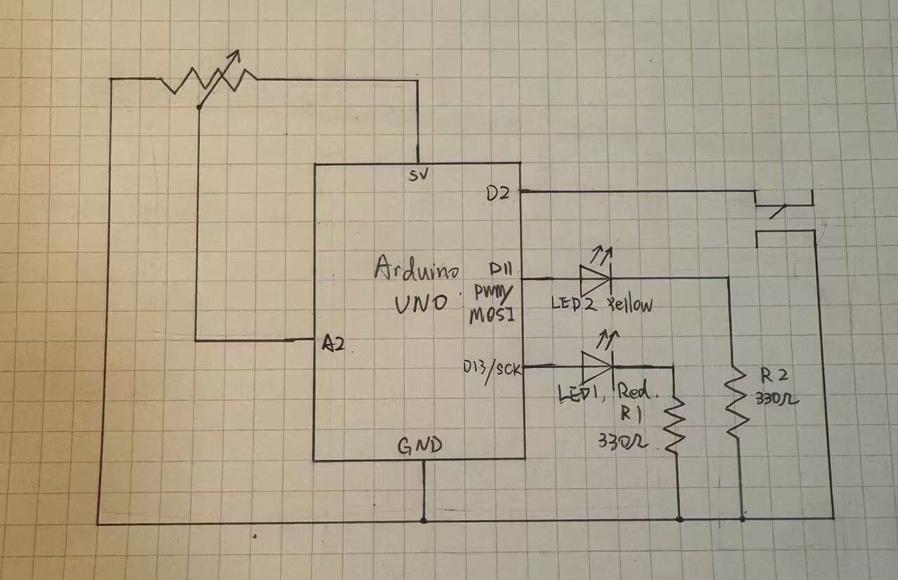
The potentialmeter input is plugged into analog pin 2, anolog output is connected to the yellow LED2 through digital pin 11, digital output is connected to red LED1 though digital pin 13. A 10k resister was not used with the push button because I tried the INPUT_PULLUP, which utalized the resistors default inside the arduino chip.
Code Snippet
if (buttonState==LOW){
  //turn off yellow LED
  analogWrite(analogLed,0);
  //Bling red LED
  digitalWrite(digitalLed,HIGH);
  delay(sensorValue);
  digitalWrite(digitalLed, LOW);
  delay(sensorValue);
}else{
  //Turn off red LED
  digitalWrite(digitalLed,LOW);
  //control yellow LED brightness
  analogWrite(analogLed, sensorValue/4);
  delay(30);
}
This is the if-else loop that is responsible for the logic of the circuit. When the button is pressed it turns off the yellow LED and make the red LED blink with a delay od the potentialmeter reading. Since the reaidng is betwenn 0 and 1023 the longest delay is about 1s which is a resonable wait. When the button is pressed, the red LED turns off and the makes the brightness of the yellow LED 1/4 of the analog reading, mapping it to 0-255.
Some space forimprovement is that a regular switch can easily replace the function of the push button, even allowing the user to keep the circuit in whichever state they prefer, though it would bea bit less fun. It would be better if I find a way to display the uniqueness of the push button as a digital input.
AI was not used in this assignment.