
VDO:
https://youtu.be/dxPHEA3eniM?si=DXep_sax1CEpxgOV
Hand-Drawn Schematic:
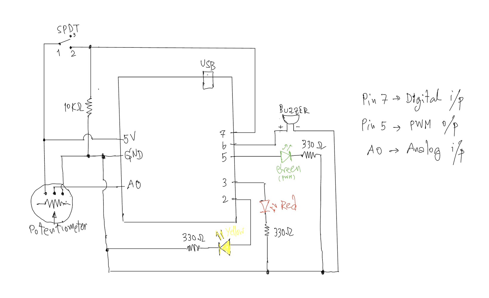
Arduino Analog & Digital Interaction Project
Concept:
This project explores the use of both analog and digital inputs in Arduino by combining a potentiometer and a switch to control multiple outputs in a meaningful way. The goal was to clearly demonstrate the difference between discrete digital control (on/off) and analog control (gradual change) through LEDs and a buzzer.
The system is designed as a simple “alert level controller.” The switch acts as a master control, while the potentiometer simulates changing intensity levels.
⸻
Components Used:
• Arduino UNO
• Potentiometer (10K) – analog sensor
• SPDT Slide switch – digital sensor
• Yellow LED – digital output
• Green LED – analog output (PWM)
• Red LED – warning indicator
• Buzzer
• Resistors (330Ω for LEDs, 10KΩ for switch)
• Breadboard and jumper wires
⸻
How It Works:
1. Digital Control (Switch + Yellow LED)
The SPDT slide switch is connected using a resistor (10KΩ).
• When the switch is OFF → the system is inactive and all outputs are off.
• When the switch is ON → the system activates, and the yellow LED turns on.
This demonstrates a digital output(discrete), where the LED is either fully ON or OFF.
⸻
2. Analog Control (Potentiometer + Green LED)
Once the system is ON, the potentiometer is used to control the brightness of the green LED.
• The potentiometer outputs a value from 0 to 1023 using analogRead().
• This value is mapped to 0–255 using map() to control LED brightness.
• The green LED gradually becomes brighter as the potentiometer is turned.
This demonstrates an analog output, where brightness changes smoothly instead of instantly.
⸻
3. Threshold Behavior (Red LED + Buzzer)
When the potentiometer reaches a high value (above a defined threshold), the system enters a warning state:
• The green LED turns off
• The red LED turns on
• The buzzer starts to sound
This creates a clear transition from a normal state to a warning state, adding a more interactive and creative behavior to the system.
⸻
Code I proud of:
if (potValue < THRESHOLD) {
      // analog mode: dimmable green LED
      brightness = map(potValue, 0, THRESHOLD, 0, 255);
      analogWrite(GREEN_LED, brightness);

      digitalWrite(RED_LED, LOW);
      noTone(BUZZER);
    }
    else {
      // if >= threshold -> green LED off, red LED on, buzzer sounds
      analogWrite(GREEN_LED, 0);
      digitalWrite(RED_LED, HIGH);
      tone(BUZZER, 1000);
    }
Reflection:
This project helped me clearly understand the difference between analog and digital signals in Arduino. The switch provided a stable binary input (HIGH/LOW), while the potentiometer allowed continuous control.
One important concept I learned is the voltage divider, which is used in both the potentiometer and the pull-down resistor setup. It ensures stable and readable input values.
I also learned that analog interaction is not always perfectly linear (as earlier I tried the other sensor like Press Sensor FSR402), which is why the potentiometer was a better choice for demonstrating smooth brightness control.
Overall, this project successfully combines multiple inputs and outputs into a simple but interactive system.
⸻
Conclusion:
By combining a digital switch and an analog potentiometer, this project demonstrates:
• Clear digital vs analog behavior
• Smooth LED fading using PWM
• Conditional logic with thresholds
• A simple interactive system design
Reference: