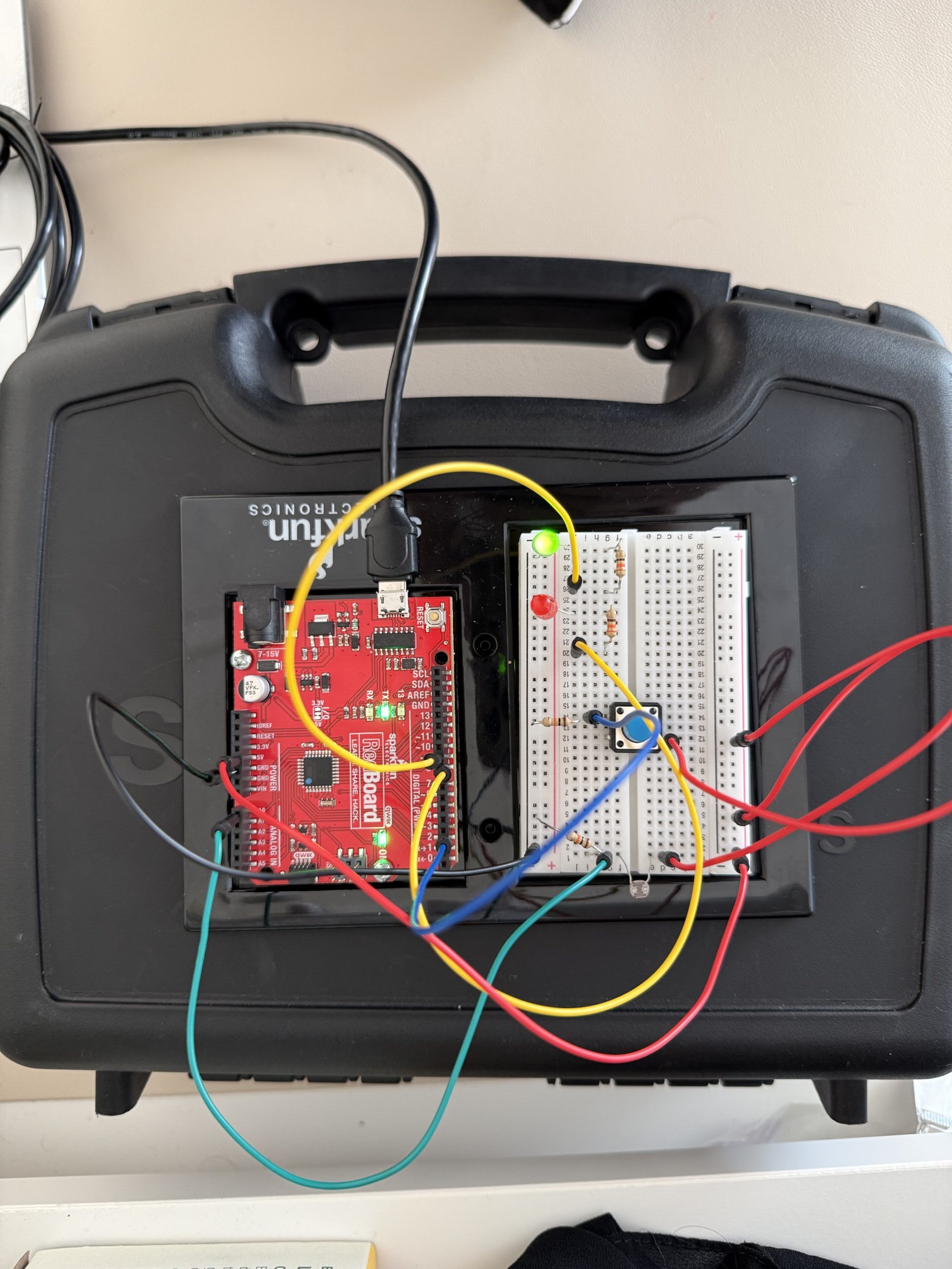
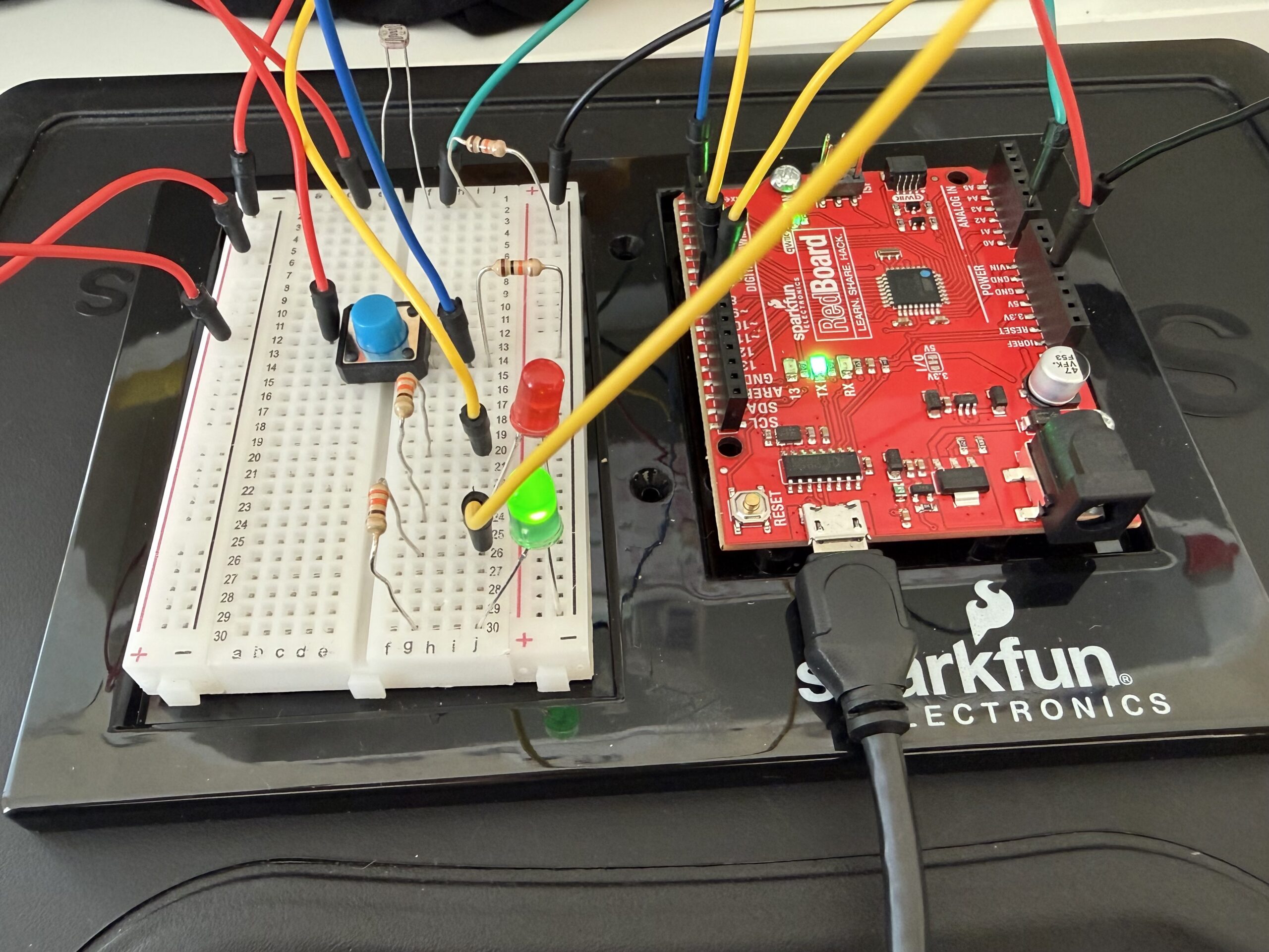
Here are pictures and videos:
^ if that does not work here is the google drive link to the video:
https://drive.google.com/file/d/1cqjdY0IDc7IcCNzmsgcox7MWBKphB9yT/view?usp=sharing
Here is the GitHub link: https://github.com/farahshaer/Intro-to-IM/blob/56d1cd018f4c8af02c5288f277d48bbc5288f498/sketch_apr4a_20260404184101.ino
Overall concept
So, for this project, I wanted to make a system where red and green LEDs react to the light in the environment. I used a photoresistor to detect the amount of light in the environment. When it’s dark, the red LED turns on, and when it’s bright, the green LED lights up. There is also a button that lets you make the LEDs blink if you want.
Code Highlight
One part of the code that I am particularly proud of is where the LEDs respond to the light and button input, basically the logic that decides which LED to turn on. I used digitalWrite for the red LED to turn it fully on or off, and analogWrite for the green LED for brightness control using PWM. It also makes the LEDs blink if the button is pressed. Here is the code snippet:
//Dark Environment
  if (sensorValue < 790) {        //if the light level is below the midpoint value = dark
    digitalWrite(greenLED, LOW);  //turns the green led off in the dark
    if (buttonState == HIGH) {    //and if the button is pressed make the red led blink
      digitalWrite(redLED, HIGH);
      delay(50);
      digitalWrite(redLED, LOW);
      delay(50);
    } else {
      digitalWrite(redLED, HIGH);  //if the button is not pressed keep the red led on
    }
  }
  //Bright Environment
  else {                                  //if the light level is above the midpoint value = light
    digitalWrite(redLED, LOW);            //turn off the red led in the light
    if (buttonState == HIGH) {            //if the button is pressed make the green led blink
      analogWrite(greenLED, brightness);  //to set the brightness based on the mapped sensor values
      delay(50);
      analogWrite(greenLED, 0);
      delay(50);
    } else {                              //if the button is not pressed keep the green led on
      analogWrite(greenLED, brightness);  //to set the brightness based on the mapped sensor values
    }
  }
}
Reflection/Future work
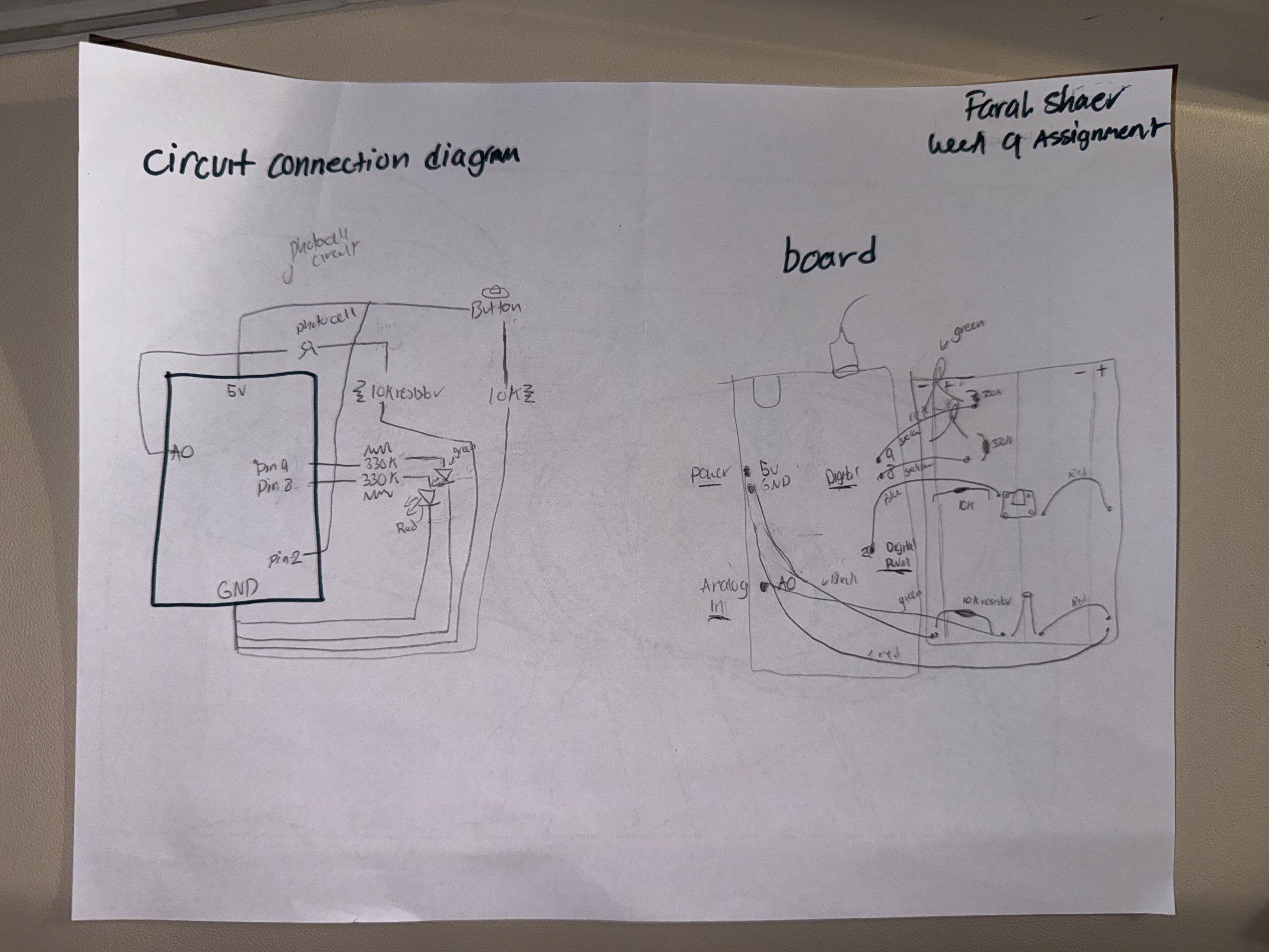
For the wiring, it was pretty straightforward. The photocell is connected to the analog pin A0 and reads the light level, and is connected to a 10k resistor. The red LED is connected to digital pin 8 because it only needs on/off control. The green LED is connected to PWM pin 9, allowing its brightness to be controlled through code using analogwrite. The button is connected to digital pin 2, and its state is read using digitalRead. In the code, the sensor values are first constrained to a usable range and then mapped to a PWM range of 0-255 using the map function. This allows the green LED’s brightness to adjust to the amount of light detected by the photocell. The code then checks whether it is dark or bright, turns the correct LED on, and makes it blink if the button is pressed.
This assignment was very helpful. I used the lecture slides for reference. It helped me learn how to combine the sensors leds and buttons. Using the PWM for the green LED allowed me to explore the brightness control instead of just turning the LED on and off. Also, looking at the photocell readings in the serial monitor helped me understand the sensor range and change it in the constrain and map functions.
For future improvements, I could add more LEDs and maybe make the blinking speed or brightness based on how dark or bright it is, or I could incorporate more sensors to make the system even more interactive.
Here is my hand-drawn schematic: