Concept
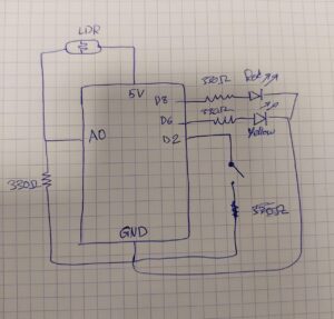
This project uses one digital sensor (a toggle switch) and one analog sensor (an LDR) to control two LEDs. The toggle switch turns a green LED fully on or off, and the LDR controls the brightness of a yellow LED. The darker it gets, the brighter the LED becomes.
Schematic
Code Snippet
void loop() {
  // Switch controls green LED
  int switchState = digitalRead(switchPin);
  if (switchState == LOW) {
    digitalWrite(greenLED, HIGH);
  } else {
    digitalWrite(greenLED, LOW);
  }

  // Analog part: light sensor controls yellow LED brightness
  int lightVal = analogRead(ldrPin);
  int brightness = map(lightVal, 0, 1023, 255, 0); // darker room = brighter LED
  Serial.println(brightness);
  analogWrite(yellowLED, brightness);
}
Reflection and Future Improvements
This project helped me clearly see the difference between analog and digital inputs: the LDR smoothly controls LED brightness while the switch simply turns the other LED on or off. Moving forward, I’d like to try adding more outputs, like a buzzer or an RGB LED, to make the reactions more expressive.

