I want to make an interactive system that allows a plant to “communicate” its environment and feelings through a digital avatar. Using an Arduino, the project reads light levels and touch interactions, and sends this data to a p5.js sketch. The p5.js interface visualizes the plant’s mood in real time using simple animations, color changes, and sound.
For example, if the plant is in low light, the avatar may appear tired or sleepy, and the RGB LED on the Arduino will turn a soft blue. If the user touches the plant (using a button or capacitive sensor), it responds with a cheerful animation and sound, and the LED may flash in a brighter color.
It’s intended to be playful, meditative, and emotionally engaging—bridging physical and digital experiences in a way that encourages users to care for their environment.
Before diving into the first task, we began by loading the sample Arduino and p5.js code from the previous class. We then read through each line to see how Arduino connects and communicates with p5. This served as a helpful foundation to jumpstart our workflow.
Task 1:
After reviewing the code and identifying the necessary components, we proceeded to build the circuit using a sliding potentiometer. Using analogRead from pin A0, we captured the potentiometer’s data and sent it to p5. The values ranged from 0 to 900, so we divided them by 2.25 to map them to the x-position on the canvas, ensuring smooth and accurate movement. A global variable ‘pos’ is updated and mapped into the x position of the ellipse.
Here is the p5.js code:
let pos = 0;
function setup() {
  createCanvas(400, 400);
}

function draw() {
  background(220);
  ellipse(pos,200,100,100);
}

function keyPressed() {
  if (key == " ") {
    setUpSerial(); // setting up connection between arduino and p5.js
  }
}

function readSerial(data) {

  if (data != null) {
    let fromArduino = trim(data) + "\n";
    pos = fromArduino/2.25; // to map 0 to 900 in the right range in p5.js (400 by 00) canvas
    writeSerial(sendToArduino);
  }
}
and the arduino code:
int sensor = A0;

void setup() {
  Serial.begin(9600);
  pinMode(LED_BUILTIN, OUTPUT);
  digitalWrite(led, HIGH);
  delay(200);
  digitalWrite(led, LOW);

  // starting the handshake
  while (Serial.available() <= 0) {
    digitalWrite(LED_BUILTIN, HIGH); // on/blink while waiting for serial data
    Serial.println("0"); // send a starting message
    delay(300);            // wait 1/3 second
    digitalWrite(LED_BUILTIN, LOW);
    delay(50);
  }
}

void loop() {
  digitalWrite(LED_BUILTIN, LOW);
  int sensor = analogRead(A0);
  Serial.println(sensor); // sending sensor information to p5.js

}
We decided to create an input box where if the user inserted a number between 0-255 and pressed enter, it would then reflect the corresponding brightness onto the blue LED on the breadboard. It was a relatively simple implementation that required very minimal code changes.
Here’s the p5.js code:
let ledval = 0;
let input;

function setup() {
  createCanvas(400, 400);
  input = createInput('');
  input.position(120, 100);
}

function draw() {
  background(220);
}

function keyPressed() {
  if (key == " ") {
    setUpSerial(); // setting up connection
  }
}

  if (data != null) {
    let fromArduino = trim(data);
    let sendToArduino = input.value() + "\n";
    writeSerial(sendToArduino);
  }
}
and the arduino code:
int led = 3;

void setup() {
  Serial.begin(9600);
  pinMode(LED_BUILTIN, OUTPUT);
  pinMode(led, OUTPUT);

  // Blink them so we can check the wiring
  digitalWrite(led, HIGH);
  delay(200);
  digitalWrite(led, LOW);

  // start the handshake
  while (Serial.available() <= 0) {
    digitalWrite(LED_BUILTIN, HIGH); // on/blink while waiting for serial data
    Serial.println("0,0"); // send a starting message
    delay(300);            // wait 1/3 second
    digitalWrite(LED_BUILTIN, LOW);
    delay(50);
  }
}

void loop() {
  // wait for data from p5 before doing something
  while (Serial.available()) {
    digitalWrite(LED_BUILTIN, HIGH); // led on while receiving data

    int ledVal = Serial.parseInt();
    if (Serial.read() == '\n') {
      analogWrite(led, ledVal);
      delay(5);
    }
  }
  digitalWrite(LED_BUILTIN, LOW);

}
For the last task, we needed to first open up and examine the given gravity wind code. We identified two key things we could alter that would complete the given task at hand: the “wind.x” variable and the “(position.y > height-mass/2)” IF statement. We could map the analog value we read in from pin A0 to the wind.x position to alter the ball’s position on the x axis and since the aforementioned IF statement indicates when the ball has touched the ground, we could simply sneak in a line that sets a boolean flag to true and sending this to arduino and performing a digitalWrite (replacing the previous analogWrite from the input()).
Here’s how we did it in p5.js:
let velocity;
let gravity;
let position;
let acceleration;
let wind;
let drag = 0.99;
let mass = 50;
let floor = false;

function setup() {
  createCanvas(640, 360);
  noFill();
  position = createVector(width/2, 0);
  velocity = createVector(0,0);
  acceleration = createVector(0,0);
  gravity = createVector(0, 0.5*mass);
  wind = createVector(0,0);
}

function draw() {
  background(255);
  applyForce(wind);
  applyForce(gravity);
  velocity.add(acceleration);
  velocity.mult(drag);
  position.add(velocity);
  acceleration.mult(0);
  ellipse(position.x,position.y,mass,mass);
  if (position.y > height-mass/2) {
      velocity.y *= -0.9;  // A little dampening when hitting the bottom
      position.y = height-mass/2;
      floor = true; // light up the LED!
    }

}

function applyForce(force){
  // Newton's 2nd law: F = M * A
  // or A = F / M
  let f = p5.Vector.div(force, mass);
  acceleration.add(f);
}

function keyPressed(){
  if (key == " ") {
    setUpSerial(); // setting up serial connection
  }

  if (keyCode==LEFT_ARROW){
    wind.x=-1;
  }
  if (keyCode==RIGHT_ARROW){
    wind.x=1;
  }
  if (key=='s'){ // changed from space to 's' since SPACEBAR is used to initiate serial connection pairing to arduino
    mass=random(15,80);
    position.y=-mass;
    velocity.mult(0);
  }
}

function readSerial(data) {
  if (data != null) {
    let fromArduino = trim(data);
    wind.x = map(fromArduino, 0, 912, -2, 2); // mapping sensor's analog value to ball's wind x axis value

    let sendToArduino = Number(floor) + "\n";

    writeSerial(sendToArduino);
    floor = false; // turning off blue LED
  }
}
*We used the Number() function to convert the boolean flag value to an integer value since initially we were encountering issues where it was not actually being send as a numeric value to turn on the LED in digitalWrite.
and the arduino code:
int sensor = A0;
int led = 3;

void setup() {
  Serial.begin(9600);
  pinMode(LED_BUILTIN, OUTPUT);
  pinMode(led, OUTPUT);

  // Blink them so we can check the wiring
  digitalWrite(led, HIGH);
  delay(200);
  digitalWrite(led, LOW);

  // start the handshake
  while (Serial.available() <= 0) {
    digitalWrite(LED_BUILTIN, HIGH); // on/blink while waiting for serial data
    Serial.println("0,0"); // send a starting message
    delay(300);            // wait 1/3 second
    digitalWrite(LED_BUILTIN, LOW);
    delay(50);
  }
}

void loop() {
  // wait for data from p5 before doing something
  while (Serial.available()) {
    digitalWrite(LED_BUILTIN, HIGH); // led on while receiving data

    int ledVal = Serial.parseInt();
    if (Serial.read() == '\n') {
      digitalWrite(led, ledVal);
      delay(5);
    }
  }
  digitalWrite(LED_BUILTIN, LOW);
  int sensor = analogRead(A0);
  Serial.println(sensor);

}
My idea is to create a volleyball game that allows users to play against a wall, bouncing the ball in circles to earn points all while trying to keep the ball up off the ground.
The arduino will consist of 6 sensors connected to it, aligned along the edge of the wall on the floor, pointing up and equally spaced. These sensors will detect anytime a ball bounces along the wall above the sensors. Then, there will be a projector behind the player. This will project a p5 sketch with sporadically appearing circles projected on the wall. As the player bounces/passes the ball into the circles, the sensors will detect an input and the player will score the point and make that circle disappear, and a new circle will appear, and so on. The goal is to get the most points in 60 seconds of play. The player is naturally penalized for dropping or losing the ball when they are forced to go and pick it up and return back to continue playing as they are on a timer. The player must stand behind a red tape line I will place a distance from the playing wall surface.
Ever since I was little, I’ve been fascinated by fairies — the idea that tiny magical beings could exist just beyond what we can see has always made the world feel more enchanted. That love, combined with a growing interest in interactive art and physical computing, inspired me with this thought
The Concept
The Fairy’s Wish is a playful, interactive project where players guide a brave little cat through an enchanted forest to collect three magical items. The controls aren’t just keyboard keys — they’re real-world physical inputs (joystick, buttons, maybe even pressure pads) connected through an Arduino.
When the cat finally reaches the fairy and completes the quest, something truly magical happens. A real-life fairy — represented by a handmade Barbie doll with glittering wings — comes to life. Her wings flutter using servo motors, her body glows with soft LED lights, and she thanks the player with a glowing blessing, making the whole experience feel magical and earned.
Ideas in Motion
The core idea started with this question:
What if beating a game didn’t just give you a virtual reward, but sparked something real in front of you?
From there, I began sketching:
Physical Controls: A joystick to move the cat, a big friendly button for jumping, and possibly a rotating dial to navigate hidden paths. All inputs run through Arduino to control the game made with p5.js.
Game Design: The forest has three areas, each holding a different magical item. Players solve simple puzzles or navigate mini challenges to unlock them. Dialogue boxes from forest spirits guide the way.
The Real-World Fairy: Built with a Barbie, fairy wings made from wire + sheer fabric or acetate, servo motors hidden behind her, and color-changing LEDs in her base. Her activation is synced with the game logic — so she only “blesses” you when you’ve truly earned it.
Sound and Light: I’m exploring the idea of adding a soft melody that plays when the fairy activates — maybe even using a piezo speaker or pre-recorded message. I’d also love to add sparkly lights or a mini bubble machine for that extra fairy dust moment.
Production Plans & Future Thoughts
Here are some dreams I’d love to work toward:
Make the fairy’s wings feel more alive — using multiple servos for a more natural fluttering motion.
Create a “fairy blessing” moment with lighting effects and maybe even scent (imagine a lavender puff when you succeed).
Build a portable fairy shrine: a beautiful little display box that holds the fairy and all the electronics, decorated like a miniature forest shrine.
Expand the story into a chapter-based quest where the cat meets more characters, with the real-world doll responding differently depending on what items were collected.
I’m using p5.js to make the game. It’s a simple way to build cute graphics and animations with code.
I’m using Arduino to handle the physical parts (like the joystick and fairy’s wings).
When your cat touches the fairy in the game, p5.js sends a message to the Arduino.
Then the fairy doll lights up and her wings flutter (with servo motors).
It’s like the game and the real world are talking to each other!
Some Cool Features I Want to Add
I’m still building it, but here’s what I’m planning:
Joystick movement for the cat — maybe even a big “jump” button.
A forest with different paths and challenges to find each magical item.
The fairy doll will glow in different colors depending on what you collected.
A soft melody when the fairy activates (maybe using a tiny speaker).
A beautiful mini “fairy shrine” where she lives — decorated like a real enchanted forest!
Challenges (aka The Tricky Stuff)
Timing: Making sure the fairy only reacts at the exact right moment in the game.
Syncing Arduino with p5.js smoothly — there’s some trial and error here.
Making the wings move naturally without looking too robotic.
But I’m excited to figure it all out!
Future Thoughts
Once I finish the basic version, I’d love to:
Add more levels or characters to the game.
Let players customize their cat before starting the journey.
Add sound effects and sparkles for extra magic.
Maybe even make a version that other people can play at an art show or event.
For this project, I wanted to explore create a Disney/Pixar themed game. I got inspired by the core memories idea in Inside Out and subway surfers which e which was my favourite game to play growing up and so I decided to design an Inside Out racing game.
The digital game, built in p5.js, represents the mental world of a child’s mind. At first, the user enters his/her core memory and then the race starts. The player dodges Disney villains (representing negative emotions like fear, jealousy, and anxiety) and collects Disney heroes (representing friendship, family, hope, and self-acceptance) as power-ups. As the player progresses, either Joy or Sadness physically moves forward on a real-life race track depending on the player’s choices and collisions. If Sadness wins, a memory ball turns blue. If Joy wins, it glows yellow.
The goal of the game is to protect the player’s game memory and collect as many power ups as possible so that joy wins and the memory ball turns yellow.
How It Works:
The p5.js Game:
The main game interface is a side-scrolling runner similar to Subway Surfers. The player character avoids villains (like Scar, Maleficent, or Ursula) and collects heroes (like Buzz Lightyear, Elsa, and Baymax). Each obstacle or power-up has a symbolic connection to an emotion or social concept:
Jealousy→ Evil Queen (Snow White)
Fear→ Randall (Monsters Inc.)
Anxiety→ Mother Gothel (Tangled)
Friendship→ Woody and Buzz
Family→ Elsa and Anna
Self-doubt→ Forky (Toy Story)
Memory Loss→ Dory
Stereotypes→ Judy Hopps and Nick Wilde (Zootopia)
When a villain is hit, Sadness moves closer to the finish line. When a hero is collected, Joy moves ahead.
The game is built using OOP principles and screen transitions, just like in my previous project. Each frame checks for collisions, updates the character’s position, and sends signals via serial communication to the Arduino based on whether Joy or Sadness should move forward.
Arduino:
The physical track features 3D-printed figures of Joy and Sadness mounted on sliding mechanisms (like small carts or servo-driven platforms). The Arduino receives signals from p5.js via serial and moves either character forward in small steps.
At the finish line, each figure holds a translucent memory ball (ping pong ball or resin sphere). Using RGB LEDs, the Arduino lights up the ball:
Yellow: for Joy (Emotion: Happiness)
Blue: for Sadness (Emotion: Nostalgia/Grief)
Challenges:
One big challenge I’m still figuring out is how to power the LEDs inside the moving figures.
I’m also still testing how I’ll light up the memory ball when the character reaches the end. It might involve placing a proximity sensor at the finish line, or coding a timer that tracks when one character hits the end point based on movement count
Concept:
For my final project, I want to develop an interactive system which mixes emotional machine learning, environmental sensing, and generative art. The core idea is to create an ambient environment that responds dynamically to human emotions and gestures. Using ML5.js, I aim to analyze real-time inputs like facial expressions (via FaceAPI) or body movements (via PoseNet) from a webcam feed, translating these into evolving light patterns using Arduino-controlled LEDs and abstract visualizations in p5.js.
Challenges:
First, I need to determine how to reliably connect ML5.js (running in a browser) with Arduino, maybe through the WebSerial API, while ensuring real-time synchronization between emotion detection, visualization, and lighting. Latency concerns me, as even minor delays could break the immersive experience. Second, mapping emotional states (e.g., “happy” or “angry”) to artistic outputs feels subjective; I’ll need to experiment with parameter mappings (color, motion, sound).
I resonate with the reading’s premise that disability design must evolve from mere practicality to an embrace of fashion and artistic expression. This shift not only empowers users but enables them to sculpt their identities—both in how they see themselves and how they are seen by others—through distinctive, personalized devices. Take eyewear as a poignant illustration of this concept: its triumph lies in the diversity of choices, such as an array of frame styles that resonate culturally, enabling individuals to exude confidence rather than embarrassment. In the same vein, Mullins’ prosthetic designs highlight how aesthetics can harmonize with personal flair, bolstering self-worth and enhancing social engagement, much like the way we choose our attire or adorn ourselves with jewelry.
To further this dialogue, I suggest harnessing innovative, interactive design tools like p5.js to create dynamic platforms where users can tailor assistive devices in real-time. By allowing them to select shapes, hues, and materials that echo their personal tastes and lifestyle choices, we align with the reading’s call for user autonomy. This transforms design into a participatory experience where individuals take an active role in shaping the aesthetics and functionality of their devices, akin to selecting outfits that express their unique style. Such tools have the potential to democratize the design process, making it accessible and inclusive while cultivating a culture that celebrates disability as a vibrant expression of individuality.
Moreover, this approach tackles the reading’s concerns about universal design by emphasizing personalized solutions. By incorporating sensor-driven inputs like gesture or voice controls, these platforms can cater to a broad spectrum of abilities, reflecting the user-friendly elegance reminiscent of the iPod interface. This not only fulfills the reading’s vision of design as an act of empowerment but also positions technology as a dynamic intersection of art, fashion, and disability, resulting in devices that are not only functional and beautiful but also deeply personal.
Final Project Preliminary Concept:
My concept combines generative music and art with arduino through a new type of sensor (Heart Rate Sensor). This would connect to the radial artery on the wrist, and the user’s heart rate will be sent to arduino and then through a serial connection to p5.js in real-time. p5.js will have a pre-defined set of musical nodes and visual graphics which will respond to the user’s heart rate, this is effectively a visual data representation of BPM.
The output then is the generative artwork (in synch and contributing to the experimental generated music). The experience would last 2 minutes and the user’s input to change the visuals and music.
I also want to incorporate 3 midi style touch sensors which facilitate the person’s interaction with my project. To make them intuitive , I will place them vertically (left for back, middle for pausing/continuing, right to go forward) which will allow the user to filter through different algorithms of how the musical nodes and visual representations are produced.
Graham Pullin’s Design Meets Disability made me reflect on how design often operates in rigid categories, medical vs. fashionable, functional vs. expressive, and how these binaries fail people with disabilities. The reading’s core idea, that assistive tools deserve the same creative energy as mainstream products, feels both radical and obvious. Why shouldn’t a wheelchair or hearing aid reflect personal style? Glasses, after all, evolved from clunky necessities to fashion statements, proving that utility and aesthetics can coexist.
But I also doubted the practicality of this vision. While stylish prosthetics or colorful hearing aids could challenge stigma, design alone can’t dismantle systemic barriers like inaccessible infrastructure or costs. As one sample response noted, a sleek wheelchair might still be seen as “other” in a world built for stairs. And prioritizing aesthetics risks alienating those who need simplicity or affordability—like how designer eyewear can become unaffordable luxury. Still, Pullin isn’t arguing for style over function but for expanding what’s possible. His examples, like voice synthesizers with emotional nuance, show that “inclusive design” isn’t about trends but dignity: tools should empower users to feel seen, not hidden.
What sticks with me is the tension between individuality and universality. While choice is empowering, too many options can overwhelm. Yet Pullin’s call for diversity in design, discreet or bold, high-tech or minimalist, mirrors the broader disability experience: there’s no single “right” way to navigate the world. Maybe the goal isn’t to make assistive tools “mainstream” but to normalize their presence in design conversations. After all, glasses weren’t normalized by hiding them but by celebrating their versatility. Disability isn’t a niche market – it’s a lens (pun intended) through which we can rethink design for everyone.
void setup(){
  Serial.begin(9600);
}

void loop(){
  int pot = analogRead(A0);
  // Less responsive: smaller output range
  int xPos = map(pot, 0, 1023, 100, 300);
  Serial.println(xPos);
  delay(100);  // longer delay = slower updates
}
Challenges:
It was difficult to make the ball move gradually, this was an issue with the p5.js sketch and we added a smoothing factor to make the movement more ideal.
Exercise 2:
Arduino Code:
// Arduino: LED brightness via Serial input
const int ledPin = 6;
const unsigned long BAUD = 9600;

void setup() {
  Serial.begin(BAUD);
  while (!Serial) ;        // wait for Serial Monitor
  pinMode(ledPin, OUTPUT);
  Serial.println("LED Brightness Control");
  Serial.println("Send a number 0–255, then <Enter>:");
}

void loop() {
  // only proceed if we have a full line
  if (Serial.available()) {
    String line = Serial.readStringUntil('\n');
    line.trim();           // remove whitespace

    if (line.length() > 0) {
      int b = line.toInt();
      b = constrain(b, 0, 255);

      analogWrite(ledPin, b);
      Serial.print("▶ Brightness set to ");
      Serial.println(b);
    }
  }
}

// Fade smoothly to a target brightness
void fadeTo(int target, int speed = 5, int delayMs = 10) {
  int curr = 0;
  // read current duty by trial (not perfect, but illustrates the idea)
  for (int i = 0; i < 256; i++) {
    analogWrite(ledPin, i);
    if (i == target) {
      curr = i;
      break;
    }
  }

  while (curr != target) {
    curr += (target > curr) ? speed : -speed;
    curr = constrain(curr, 0, 255);
    analogWrite(ledPin, curr);
    delay(delayMs);
  }
}
Challenges:
For this exercise the challenges were 1: making the gradient slider animation look intuitive for functionality, and we spent a lot of time debating on whether a rainbow slider was cool or not. We decided that it was.
Exercise 3:
For this exercise we decided to build on the example provided and improve the physics of the wind as well as the animation of the ball itself. To keep track of the sensor values and ensure we are receiving consistent results, we included variables to track the potentiometer, bounce (1 results in LED high, 0 results in LED low) and the mass is just an added feature.
Challenges:
The issues we faced were plenty, including making the wind seem more realistic and making the interaction smoother. The first approach to solve this challenge were to implement debounce to discard those operations that would occur too closely during the runtime interval. We also had to be particularly careful about how often the p5.js asks for the potentiometer reading, considering the frequency of the frames displaying the visual text and the frequency of the potentiometer reading.
Arduino Code:
const int LED_PIN = 9;    // LED pin
const int P_PIN = A0;     // Potentiometer pin

void setup() {
  Serial.begin(9600);
  pinMode(LED_PIN, OUTPUT);
  digitalWrite(LED_PIN, LOW); // Initial LED state

  // Handshake: Wait for p5.js to send a start signal
  while (Serial.available() <= 0) {
    Serial.println("INIT"); // Send "INIT" until p5.js responds
    delay(100);             // Avoid flooding
  }
}

void loop() {
  // Check for incoming serial data
  if (Serial.available() > 0) {
    char incoming = Serial.read(); // Read a single character
    if (incoming == 'B') {        // p5.js sends 'B' followed by 0 or 1
      while (Serial.available() <= 0); // Wait for the value
      int bounce = Serial.read() - '0'; // Convert char '0' or '1' to int
      digitalWrite(LED_PIN, bounce);    // Set LED (0 = LOW, 1 = HIGH)
    }
    else if (incoming == 'R') {       // p5.js requests potentiometer reading
      int potValue = analogRead(P_PIN); // Read potentiometer (0-1023)
      Serial.println(potValue);         // Send value
    }
    // Clear any remaining buffer (e.g., newlines)
    while (Serial.available() > 0) {
      Serial.read();
    }
  }
}
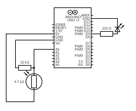
In this setup, I connected a photoresistor to analog pin A0 of the Arduino. The changing light levels (e.g., when I moved my hand closer or farther) were read via analog input and sent to p5.js over serial communication. In p5.js, the light level was mapped to a horizontal position (X-axis) of an ellipse on screen.
As a result, the ellipse smoothly moved left to right based on how much light was detected by the sensor. The Arduino was a pure input device in this task, with no output components involved.
// Arduino Code for Photocell -> Horizontal Ellipse
const int photoPin = A0;

void setup() {
  Serial.begin(9600);
}

void loop() {
  int lightLevel = analogRead(photoPin);
  Serial.println(lightLevel);
  delay(50);  // small delay for stability
}
//Javascript:

let serial;
let latestData = "0";

function setup() {
  createCanvas(400, 400);

  serial = new p5.SerialPort();
  serial.open("/dev/tty.usbmodem13301");
  serial.on("data", () => {
    latestData = serial.readLine().trim();
  });
}

function draw() {
  background(220);
  let x = map(Number(latestData), 0, 1023, 0, width);
  ellipse(x, height/2, 50, 50);
}
Task 2: LED Brightness Controller
This task reverses the direction of interaction from Task 1. A slider on the p5.js canvas sends values (0–255) to Arduino via serial. The Arduino reads these values and writes them to a PWM pin controlling an LED, adjusting brightness in real-time.
As a result, once the slider was adjusted, the LED smoothly brightened or dimmed, creating a tangible link between screen-based and physical interaction.
// Arduino Code for LED brightness control
const int ledPin = 9;

void setup() {
  pinMode(ledPin, OUTPUT);
  Serial.begin(9600);
}

void loop() {
  if (Serial.available()) {
    int brightness = Serial.parseInt();
    analogWrite(ledPin, brightness);
  }
}
//Javascript

let serial;
let slider;

function setup() {
  createCanvas(400, 200);
  slider = createSlider(0, 255, 127);
  slider.position(20, 20);

  serial = new p5.SerialPort();
  serial.open("/dev/tty.usbmodem13301");
}

function draw() {
  background(255);
  let val = slider.value();
  text("Brightness: " + val, 20, 70);
  serial.write(val + "\n");
}
Task 3: Bouncing Ball
For this task, I modified the Gravity + Wind example from p5.js. A photocell connected to Arduino reads ambient light and sends it to p5.js to control the “wind” vector pushing up on the ball. Simultaneously, when the ball hits the bottom of the canvas, p5.js sends a “BOUNCE” signal back to Arduino, briefly lighting up an LED.
In the end, the ball was bouncing realistically, with its movement affected by how much I covered the photocell. Each bounce triggered a short LED flash, adding physical feedback to a digital interaction.
// Alternate: if p5 sends a "bounce" message, flash LED
const int ledPin = 9;
const int photoPin = A0;

void setup() {
  pinMode(ledPin, OUTPUT);
  Serial.begin(9600);
}

void loop() {
  int light = analogRead(photoPin);
  Serial.println(light);
  delay(10);

  if (Serial.available()) {
    String command = Serial.readStringUntil('\n');
    if (command == "BOUNCE") {
      digitalWrite(ledPin, HIGH);
      delay(100);
      digitalWrite(ledPin, LOW);
    }
  }
}
//Javascript

let serial;
let position, velocity, acceleration;
let gravity, wind;
let drag = 0.99;
let mass = 50;
let photoresistorValue = 0;

function setup() {
  createCanvas(640, 360);
  position = createVector(width / 2, 0);
  velocity = createVector(0, 0);
  acceleration = createVector(0, 0);
  gravity = createVector(0, 0.5 * mass);
  wind = createVector(0, 0);

  serial = new p5.SerialPort();
  serial.open("/dev/tty.usbmodem13301");

  serial.on("data", () => {
    let data = serial.readLine().trim();
    if (!data) return;
    photoresistorValue = int(data);
  });
}

function draw() {
  background(255);

  wind.y = map(photoresistorValue, 0, 1023, -2, 0);  // More wind when covered

  applyForce(gravity);
  applyForce(wind);

  velocity.add(acceleration);
  velocity.mult(drag);
  position.add(velocity);
  acceleration.mult(0);

  // Bounce
  if (position.y > height) {
    position.y = height;
    velocity.y *= -1;
    serial.write("BOUNCE\n"); // Trigger LED
  }

  ellipse(position.x, position.y, 50, 50);
}

function applyForce(force) {
  let f = p5.Vector.div(force, mass);
  acceleration.add(f);
}
Reflection:
This set of projects helped me understand both unidirectional and bidirectional interactions between hardware and software. The exercises showed how to turn real-world stimuli into digital visuals and vice versa, laying the groundwork for interactive installations, responsive art, or assistive interfaces, which is a great practice for the final project.
Reading Assignment
Reading Design Meets Disability made me rethink how design often treats disability as something to minimize or fix, rather than as an opportunity for creative expression. Pullin’s argument that assistive technologies like hearing aids or prosthetics can be expressive and personal, not just functional has really stuck with me. It challenged the default idea in my head that good design is neutral or invisible, and instead made me see how thoughtful design can actually expand what’s possible for people with disabilities.
This reminded me of Sophie de Oliveira Barata’s work, which we studied in my Communication and Technology class. Through the Alternative Limb Project, she creates prosthetics that are more than medical devices but rather artistic statements. Some are realistic, others are completely imaginative, with embedded lights or sculptural elements. Her work makes it clear that prosthetics can reflect someone’s identity and creativity, not just their physical needs. It’s a powerful example of how design can shift the narrative from limitation to self-expression.
Both Pullin’s book and Sophie’s work pushed me to question what we mean by “inclusive” or “accessible” design. It made me realize that good design goes beyond functionality by also giving people choices, visibility, and agency. I’m beginning to see inclusive design not as a constraint, but as a more thoughtful and exciting way to approach creative work.