Week 9 Production

Concept

This piece transforms a simple circuit into a puzzle. The connection between the switches is not obvious. The user needs some time to figure out what makes the LEDs light up.

The red LED changes brightness as you turn the potentiometer. Also, pressing only one of the push buttons does nothing you have to discover the specific “sweet spot” gesture. Only when all conditions align do the LEDs respond.

Video & Image Documentation

IMG_9510

Schematic Drawing

Future Improvements

A single puzzle could evolve into something far more complex by layering additional challenges:

    • Timing urgency: Buttons must be pressed within 2 seconds of entering the sweet spot, or the blue LED only stays lit for 3 seconds before requiring you to solve it again. This adds urgency and makes the victory feel earned rather than permanent.
    • Pattern memory: The blue LED blinks a simple pattern (like short-long-short) at startup. Users must recreate this rhythm with the buttons while in the sweet spot to unlock, transforming a spatial puzzle into a temporal one.

Week 9 Reading Response

The metaphor of interactive art as a directorial process reveals creative control and trust. When Igoe compares designing interactive work to directing actors, it exposes a fundamental tension in the fear of without constant explanation, our vision will be misunderstood or ignored. But this fear might actually be the enemy of good interactive work. Traditional artists can hide behind the permanence of their statement, for example, a painting doesn’t change whether viewers “get it” or not. However, Interactive artists must confront the uncomfortable reality that their work is incomplete without the audience’s participation. The most interesting implication here is that over-explanation isn’t just bad pedagogy. It’s a form of creative cowardice, a way of avoiding the vulnerability inherent in truly collaborative expression.

What strikes me about the “greatest hits” catalog is how it inadvertently maps the evolution of human-computer intimacy. The progression from theremin-like instruments (where gesture has “little meaning by itself”) to gloves (which borrow existing gestural vocabulary) to meditation helpers (which attempt to read involuntary bodily responses) represents increasingly ambitious attempts to collapse the distance between intention and interface. Yet Igoe’s skepticism about certain forms, particularly “remote hugs” and meditation helpers, suggests that some human experiences might be fundamentally resistant to technological mediation. The machine can measure breath rate and skin response, but it cannot know meditation; it can transmit signals between paired objects, but it cannot convey warmth. This raises an uncomfortable question for interactive designers: are we sometimes trying to technologically recreate experiences that derive their meaning precisely from their technological absence?

The recurring critique of projects that confuse “presence with attention” opens up a broader philosophical question about what interaction actually proves. A sensor detecting someone standing in front of a painting tells us almost nothing about engagement, yet many interactive projects treat physical proximity as evidence of meaningful exchange. This seems related to a contemporary cultural anxiety about whether we’re truly connecting with anything. We’ve become so focused on measurable interaction (clicks, views, sensor triggers) that we’ve lost sight of the immeasurable dimension where actual meaning resides. Perhaps the most radical interactive artwork would be one that deliberately resists confirming whether interaction happened at all, forcing both creator and participant to sit with uncertainty rather than seeking the reassurance of sensor data. The blink of an LED becomes a form of emotional comfort: see, something happened, you’re not alone.

Week 9 – Shadow and Light

Concept

For this project, I decided to make a small interactive game called Light & Shadow”. The concept is simple but fun: the yellow LED changes brightness depending on how much light the photoresistor (LDR) senses, and the blue LED only lights up when it’s dark and the button is pressed, basically “catching the shadow.” I liked that idea because it combines analog and digital inputs in a way that feels like a mini game.

The Process

The production process was mostly about setting up the circuit on the breadboard and figuring out how to connect everything correctly. Choosing the right resistors was harder than I expected,  sometimes the LEDs didn’t light up properly, and I had to try a few combinations before it worked. I also spent a lot of time drawing the schematic to make sense of the connections. I must have redrawn it several times to make it at least slightly understandable. Even now, I’m not 100% sure my plan is perfect, but it works!

Figure: the process of sketching the plan

The Finalized Sketch

The coding part was fun because it was simple enough to understand but still taught me a lot. I read the analog value from the photoresistor and mapped it to the brightness of the red LED, then used a simple if-statement to check the button and darkness to control the green LED. Seeing the LEDs react in real time to light and button presses made all the work feel rewarding.

int lightSensor = A0;
int buttonPin = 2;
int redLED = 9;
int greenLED = 8;

void setup() {
  pinMode(buttonPin, INPUT);
  pinMode(greenLED, OUTPUT);
  pinMode(redLED, OUTPUT);
  Serial.begin(9600);
}

void loop() {
  int lightValue = analogRead(lightSensor);    // 0–1023
  int brightness = map(lightValue, 0, 1023, 255, 0); // dark = bright
  analogWrite(redLED, brightness);

  int buttonState = digitalRead(buttonPin);

  if (buttonState == HIGH && lightValue < 400) {
    digitalWrite(greenLED, HIGH);
  } else {
    digitalWrite(greenLED, LOW);
  }

  delay(100);
}

Reflection

Overall, this project was a great learning experience. I got hands-on practice with analog and digital inputs, using resistors correctly, and writing basic Arduino code. I also learned patience, both in wiring and drawing schematics. Even though some parts were frustrating or confusing, it felt really satisfying to see the LEDs respond the way I wanted. Next time, I’d probably try adding a buzzer or even a little LCD display to make it even more interactive.

The video demonstration

IMG_8850

Week 8~: DIY Security System (Unusual Switch)

I started this project with a few ideas. One of the ideas was to make a secret switch hidden on a bookshelf. One of the books would have a piece of copper tape underneath that would touch the copper tape beneath it on the shelf. However…I realized that I didn’t have enough books to make it look convincing so I started looking around my room for something that inherently had motion to make my life easier. So I thought– what if I used my door?

Sometimes I don’t fully close my door properly and don’t know if it’s fully closed. That inspired me to make the door a switch to act like a DIY security system. I have no experience with physical computing so I had some trouble visualizing how it would look in my head, and it didn’t help that I’ve been out sick for so long. This image below was my initial concept for it.

The idea is to set up a simple LED light on the breadboard that would light up when the door was fully closed. I think I understood that pretty comfortably, but I didn’t know how the rest would work.

One of the challenges was having a mobile power source, as I was definitely not going to use my laptop for power when the Arduino kit is all the way up on the wall. I remembered that I found a battery pack in the kit so I dug that out and went down to the IM lab to ask for help and got some spare AA batteries.

The breadboard and Arduino setup was pretty straightforward but the one thing I had to think about was which wires to leave as an open connection later. From my perspective, it made sense to have the ground be split up and later connected using the copper tape so that’s what I did, while following the color conventions of PWR and GND.

I walked over to my door and applied some copper tape and set up my Arduino & battery pack on the wall using some mounting tape. However, as I worked on setting up the rest of the copper tape, I realized that this was going to very clunky– the door’s frame is not seamless with the door itself which means I need something solid to connect it; however, the copper tape was a bit too flimsy to be that connection. This is what I had so far at the time:


I was pretty perplexed by this. After some critical thinking, I realized that I could set up the arduino on the door itself. And not only that– I could even take advantage of this metal piece that helps the door slide into the lock near the door handle. This was my updated plan for my switch:

When it came to positioning the wires, I thought the copper tape would suffice to keep the wires in place but it just wouldn’t stick very well; I also needed to be able to micro-adjust and tune the location of my wires to make sure the system worked smoothly. I decided to use mounting tape again to make fine tuning the position of the wires much easier on me

I think the final result turned out to be really nice, and I’m proud of myself for adapting to the difficulties encountered during the process of mounting the project on the wall. It’s a shame I have to take it down to make future projects but I had fun making it.


Here’s a video of the final result in action; the green LED lights up to indicate a full lock when closed properly. I would not recommend installing this as your sole security system.


Reading reflection

Reading Physical Computing’s Greatest Hits and Misses alongside Making Interactive Art: Set the Stage, Then Shut Up and Listen really made me rethink how we interact with technology in creative spaces. Both texts explore the tension between human intention and technological behavior, but they approach it from slightly different angles. The first one dives into successes and failures in physical computing projects, highlighting that even the best ideas can flop if the execution ignores user experience or the unpredictability of the real world. The second reading, on the other hand, emphasizes listening to the audience and letting interactions evolve naturally, rather than forcing a rigid narrative onto the art or installation.

The most interesting part for me was the recurring theme of “letting go.” In physical computing, there’s often a desire to control every aspect of a system, to make it work perfectly according to the designer’s vision. But as the readings show, interaction is messy. Sensors misfire, people behave unexpectedly, and sometimes the “mistakes” end up being the most engaging parts of the project. I appreciated the reminder that in interactive art, and in technology projects more broadly, failure isn’t always a failure, it’s data, feedback, and sometimes even the spark for something better.

One question that came to mind while reading was: How do we balance designing for reliability with designing for surprise and emergent behavior? Both readings suggest that embracing unpredictability can make projects more engaging, but too much unpredictability can frustrate users. My takeaway is that the key might be thoughtful scaffolding, providing enough structure so that the system is understandable and responsive, while leaving space for improvisation and interaction to shape the experience.

Overall, I found these readings both inspiring and a little humbling. They reminded me that creativity in physical computing isn’t just about technical skill, it’s about curiosity, flexibility, and, honestly, patience with both technology and people.

Week 9 – Analog + Digital

Concept

When driving at night, high-beam headlights often blind oncoming drivers. I wanted to explore a simple and affordable system that encourages responsible use of headlights, something that detects oncoming glare and helps the driver automatically or manually switch to low-beam mode. This prototype uses a photoresistor to sense incoming light and a button to simulate the driver’s manual response. Two LEDs represent the vehicle’s headlight (green) and alert indicator (red).

Mechanism

Ambient calibration: when the Arduino starts, it reads the surrounding light for about 1.5 seconds and sets that as a baseline for normal nighttime brightness. This is important in the real world because ambient light differs in places, times.
Glare detection: if the light level rises significantly above that baseline, similar to when another vehicle’s high beams hit, the red LED begins to blink as a warning.
Manual response: when the button is pressed, the green “headlight” LED dims to a predefined low-beam brightness, showing that the driver has dipped the lights.
Return to normal: releasing the button restores full brightness once the road ahead is clear.

Everything happens automatically in a simple loop, using only one analog sensor (photoresistor) and one digital input (button).

Link to video demonstration

Schematic Diagram

Code highlight

The most interesting part for me was sensing ambient light accurately.
I learned how to smooth noisy analog readings using an exponential moving average (

ema = ALPHA * raw + (1 - ALPHA) * ema;


) and how to calibrate a baseline from Arduino documentation and community projects.
This taught me how real-world sensors fluctuate constantly and why filtering is crucial before making decisions based on their data.

Use Cases:

  • A bike or e-scooter headlight that adjusts automatically when another vehicle approaches.
  • A low-cost training aid for driving schools, showing how to react responsibly to high beams.
  • A foundation for smart vehicle lighting projects that aim to reduce glare and improve road safety.

Further Enhancement

1. Replace the LEDs with an actual headlight driver or relay for real-world testing.
2. Use a camera or focused photodiode to distinguish streetlights from oncoming cars.
3. Add automatic dimming without manual input, fully autonomous dipping.
4. Integrate with IoT dashboards to log light data and analyze driving environments.
5. Use a microcontroller with more PWM channels to control multiple lamps independently.

Conclusion

This project started as a simple assignment, but it quickly became a meaningful experiment in safety-oriented design.
By combining analog sensing, human interaction, and basic control logic, I built a small system that mimics how real vehicles manage headlight behavior. It reminded me that even modest hardware, guided by thoughtful logic, can address real-world problems.

Week 9 – Analog + Digital

Assignment Overview:

The goal of this task was to create a simple interactive circuit using one digital sensor (a pushbutton) and one analog sensor (an LDR) to control two LEDs on the Arduino Uno. The digital LED turns on and off when the button is pressed, while the analog LED smoothly changes brightness depending on the amount of light detected by the sensor. This task helped me understand how digital and analog inputs behave differently and how they can work together in one circuit.

My Circuit:

Planning the Schematic:

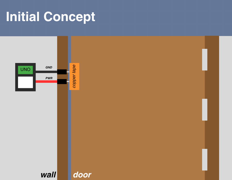
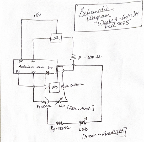
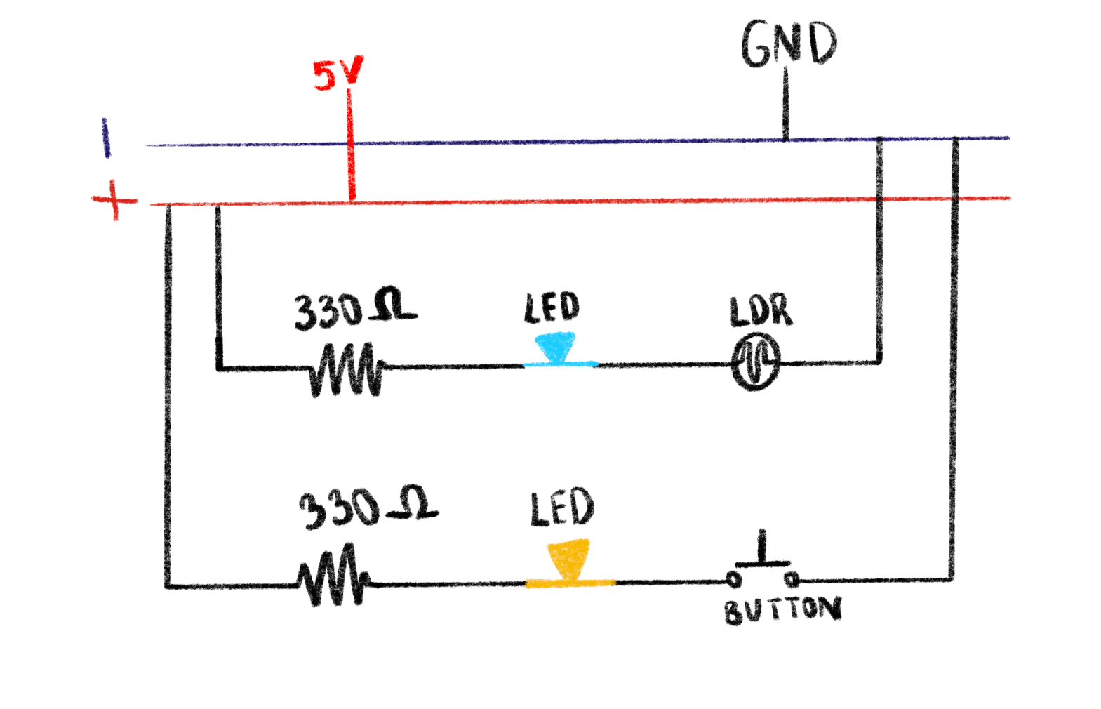
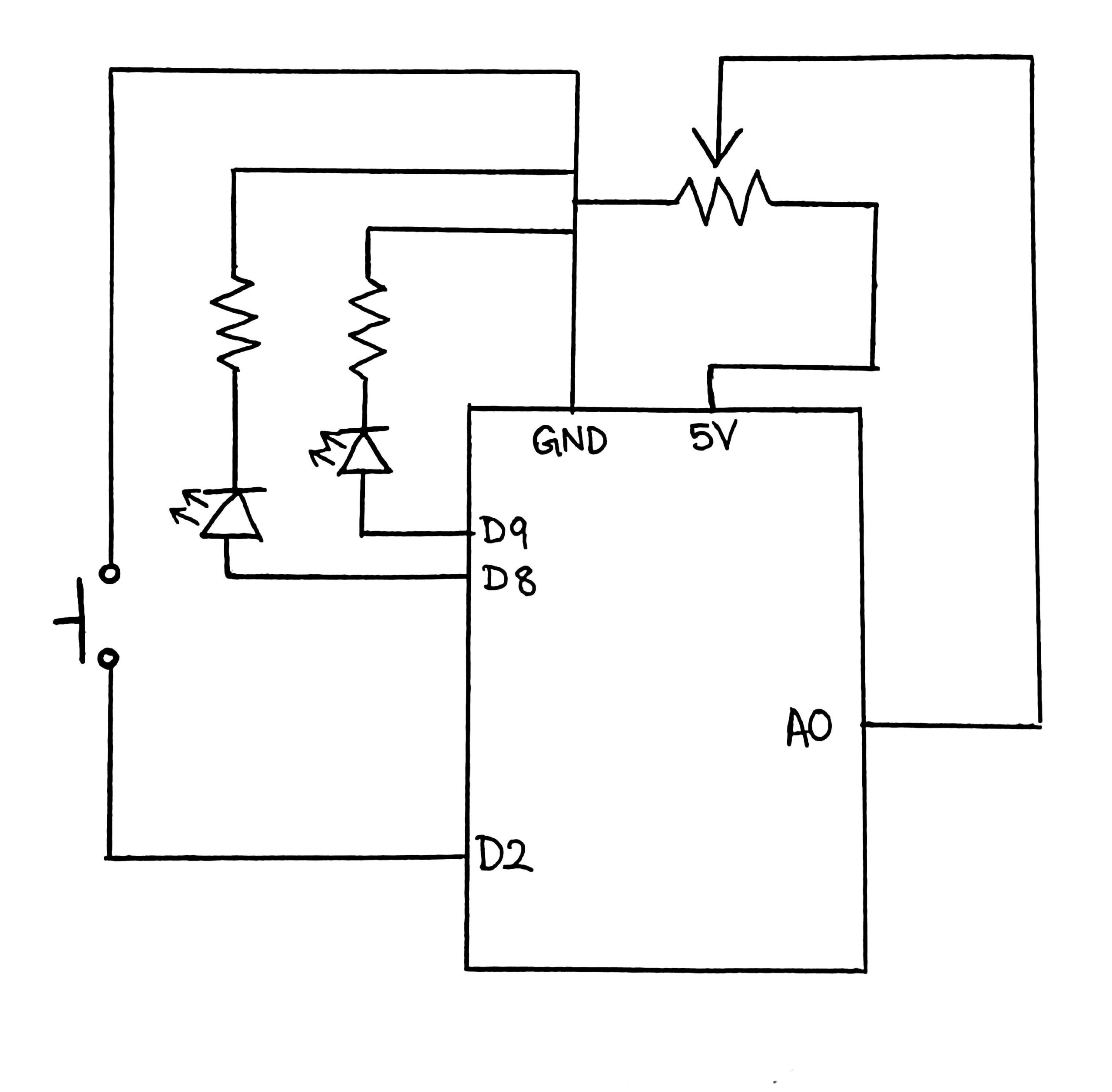
I started by sketching a schematic on my iPad on procreate to visualize how each component would connect. The schematic represents the button on pin D2, the LDR with a 330 kΩ resistor forming a voltage divider to A0, and two LEDs connected to D8 and D9, each with their own 330 Ω resistor to ground. Planning it out first helped me avoid confusion later when placing components on the breadboard and made the whole process smoother. Of course when actually going to build the board a few elements moved around but the schematic mainly shows my thought process and “map” while planning this assignment.

Building the Circuit

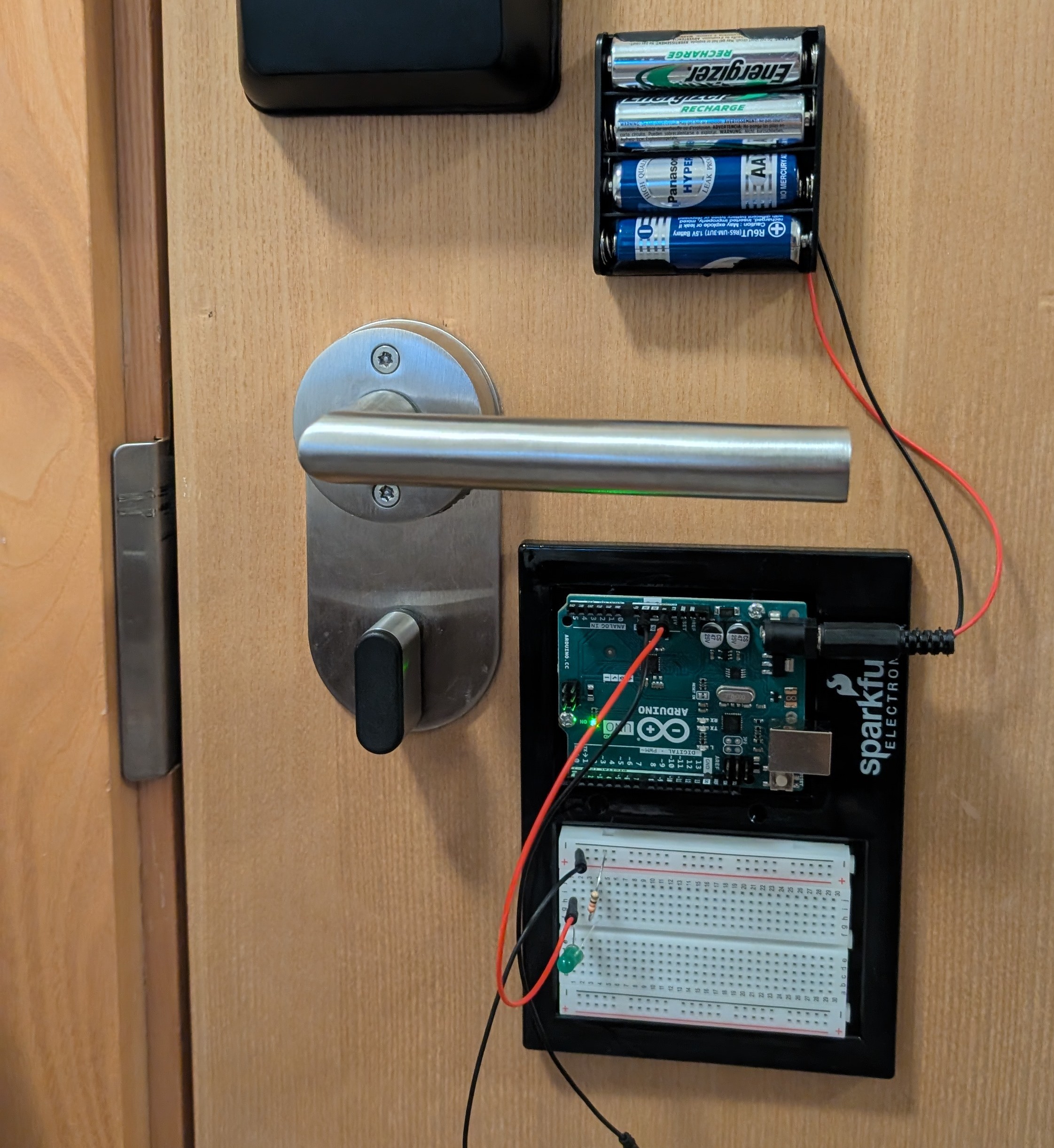
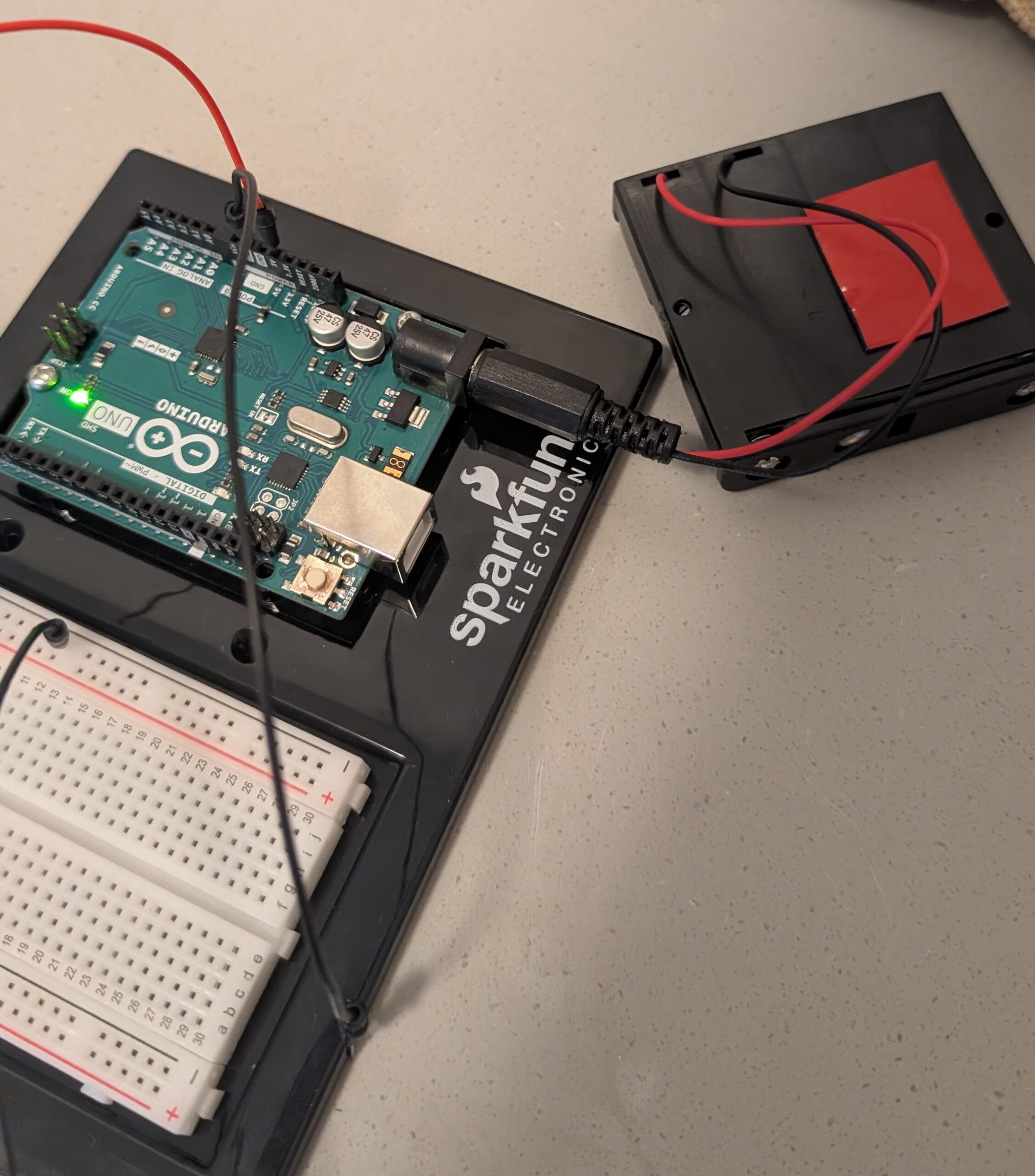
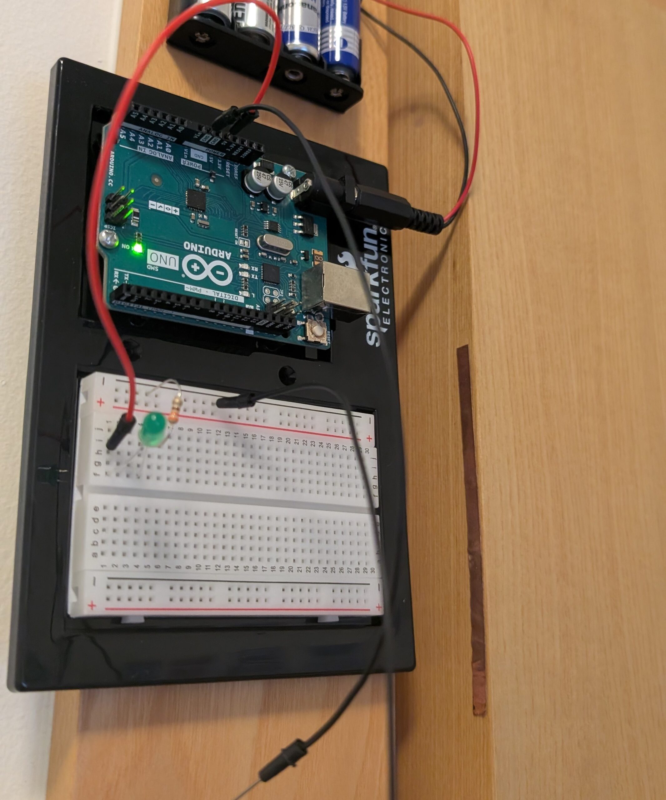
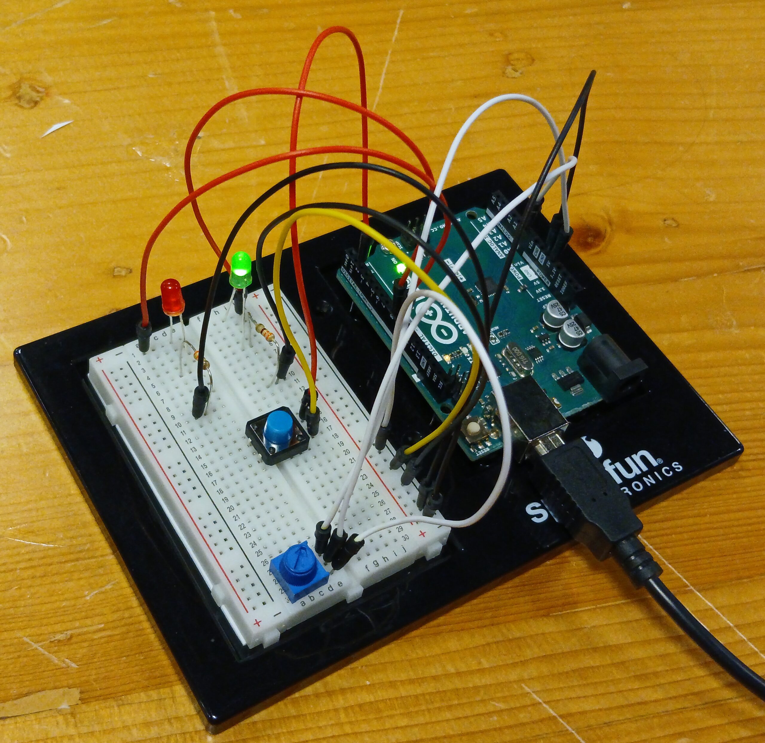
Next, I built the circuit on the breadboard, carefully following the schematic. I color-coded my jumper wires to stay organized: red for power, black for ground, green for digital signals, and yellow for analog. One small challenge was understanding that the breadboard’s left and right halves are not connected across the middle gap. Once I fixed that mistake, the circuit started to behave exactly as expected.

(Its kinda hard to see but when I cover the sensor the blue LED shifts in brightness, and the button turns the yellow LED on)

Coding Elements:

This Arduino code connects both a digital and an analog input to control two LEDs in different ways. The process starts with defining pin connections: the pushbutton on pin 2, the LDR sensor on analog pin A0, and two LEDs on pins 8 and 9. In the setup function, the button uses input pullup so it naturally stays HIGH until pressed (no external resistor needed). The digital LED on pin 8 simply turns on when the button is pressed and off when it’s released. The LDR, wired as part of a voltage divider, continuously sends changing light readings to A0. In the loop, these readings (ranging 0–1023) are mapped to 0–255 with the map function so they can control the brightness of the second LED through analogWrite on pin 9. The small delay at the end makes the light level changes smooth and stable. Overall, the code demonstrates how digital and analog signals can be read simultaneously to control different outputs in real time.

// Pin setup 
const int buttonPin = 2;   // Button connected to D2 
const int ledDigital = 8;  // Digital LED (on/off)
const int ledAnalog = 9;   // Analog LED (brightness control)
const int ldrPin = A0;     // LDR sensor connected to A0

void setup() {
  pinMode(buttonPin, INPUT_PULLUP); 
  pinMode(ledDigital, OUTPUT);
  pinMode(ledAnalog, OUTPUT);
}

void loop() {
  // Digital LED controlled by button 
  bool pressed = (digitalRead(buttonPin) == LOW); // LOW = pressed
  digitalWrite(ledDigital, pressed ? HIGH : LOW);

  // Analog LED controlled by LDR light level 
  int lightValue = analogRead(ldrPin);        // Reads LDR 
  int brightness = map(lightValue, 0, 1023, 0, 255); 
  analogWrite(ledAnalog, brightness);         // Set LED brightness

  delay(10); 
}

Troubleshooting and Adjustments 🙁

The most challenging part was honestly just starting this task. It was very overwhelming since I never used arduino before and had no experience in coding C++. It took me a few hours to look through videos and articles just to get a better understanding of how the board works, and I even gave myself a few warm up tasks, like a simple blink test which I will show later in this documentation. In this particular assignment, one of my main challenges was getting the circuit itself right. The first few times I tried to setup the button the led wouldn’t turn on and I felt like I had so many wires and it was hard to focus on what the problem was. To combat this, I took the time to properly think about my schematic as a map, then followed that instead of blindly building my board first then drawing my schematic after. This really helped me when I got frustrated, and I also took many breaks in between so I could come back to the task with fresh eyes.

Random Blink Test Experiment:

Before starting the full circuit, I experimented with a simple blink test using just one LED. I uploaded the basic Blink example to the Arduino IDE to see the LED turn on and off every second. This small test helped me understand how the digital pins, resistors, and ground connections actually worked together in a real circuit. Since it was my first time using Arduino, doing this warm-up made me more confident in reading pin numbers, placing components correctly, and recognizing how code controls physical outputs on the board.

Reflection 🙂

Overall, I really want to emphasize that i’m very proud of myself for this assignment. This showed me how coding and wiring work hand in hand, the schematic guided the hardware setup, and the code brought it to life. This was a rewarding first experience combining both analog and digital sensors in one interactive circuit.
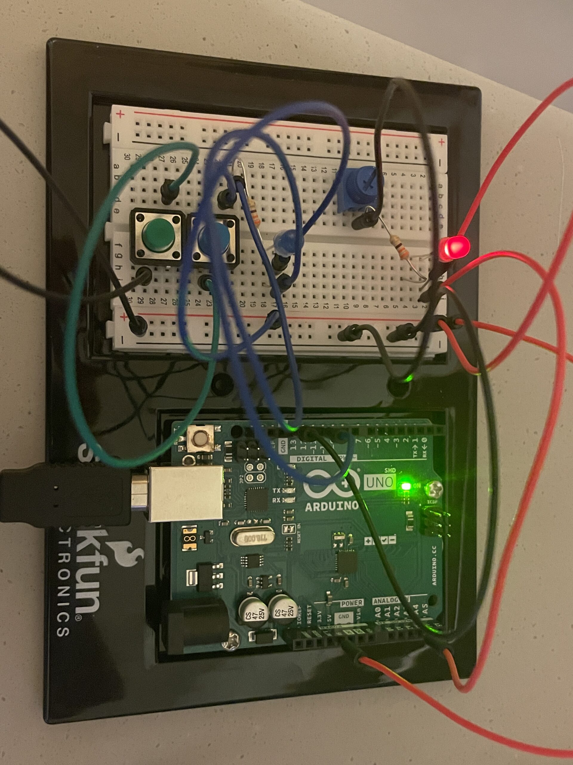
Week 9: Reaction-Time Game

Concept

I got the idea for this assignment after watching a campus cat swiftly pounce upon a tiny lizard on the wall in front of the arts center. It got me thinking about reflexes and reaction times and how I can create a mini-game out of this using Arduino. The game basically works like this:
There are two LEDs, one red and one green, one button, and one potentiometer. When the green LED turns on, the player must press the button as fast as they can. If they press it in time, the green LED flashes thrice, indicating a win, otherwise the red LED flashes, indicating the loss. If the green LED flashes, they can see their reaction time in milliseconds on the screen as well. The potentiometer controls the difficulty of the game in two ways. Firstly, it controls the random waiting period (i.e. how long the Arduino waits before turning on the green LED). A decrease in the delay between instances would need the player to be on higher alert. Secondly, it controls the reaction time threshold (i.e. how fast the player must press the button to win). At the easiest setting, the player has 400ms to react, and at the hardest, only 100ms.

Image & Video Documentation

The code

// potentiometer (A0), button (2), red LED (9), green LED (8)

const int potPin = A0;
const int buttonPin = 2;
const int greenLED = 8;
const int redLED = 9;

void setup() {
  pinMode(greenLED, OUTPUT);
  pinMode(redLED, OUTPUT);
  // use a resistor in the microcontroller instead of on the breadboard
  // causes inverted logic: not pressed - HIGH, pressed - LOW
  pinMode(buttonPin, INPUT_PULLUP); // Internal pull-up resistor
  Serial.begin(9600);
  randomSeed(analogRead(A5)); // Add some randomness
}

void loop() {
  Serial.println("Get ready");
  digitalWrite(redLED, LOW);
  digitalWrite(greenLED, LOW);
  delay(2000); // brief pause before start

  // Read difficulty from potentiometer
  int potValue = analogRead(potPin);
  int waitTime = map(potValue, 0, 1023, 1000, 3000); // 1s to 3s random wait range
  // potValue = 0 then threshold = 400 ms; 
  // potValue = 1023 then threshold = 100 ms (hard)
  int threshold = map(potValue, 0, 1023, 400, 100);  

  // Random gap time before LED turns on
  int randomDelay = random(1000, waitTime);
  delay(randomDelay);

  // Start the test
  digitalWrite(greenLED, HIGH);
  unsigned long startTime = millis();

  // Wait for button to be pressed or timeout
  bool pressed = false;
  unsigned long reactionTime = 0;

  while (millis() - startTime < 2000) {       // 2 seconds max to press button
    if (digitalRead(buttonPin) == LOW) {
      pressed = true;   // player successfully pressed the button
      reactionTime = millis() - startTime;    // calculate the player's reaction time
      break;
    }
  }

  digitalWrite(greenLED, LOW);    // turn off green LED

  if (pressed && reactionTime < threshold) {
    // Player wins
    // Display reaction time
    Serial.print("Your reaction time: ");
    Serial.println(reactionTime);

    // Flash green LED thrice to indicate win
    for (int i = 0; i < 3; i++) {
      digitalWrite(greenLED, HIGH);
      delay(150);
      digitalWrite(greenLED, LOW);
      delay(150);
    }

  } else {
    // Player loses
    Serial.println("Too slow!");
    // Flash red LED thrice to indicate loss
    for (int i = 0; i < 3; i++) {
      digitalWrite(redLED, HIGH);
      delay(200);
      digitalWrite(redLED, LOW);
      delay(200);
    }
  }

  delay(1000); // small 1s pause between game rounds
}

Reflection & Future Improvements

I had a lot of fun making this project. I think the physical setup was not too complicated, and still gave an effective output through the implemented code. In future versions, I think it would be nice to have a buzzer that gives different sounds on win/loss conditions, and maybe also implement a score counter that keeps track of how many times the player won throughout multiple rounds. I believe it would also be effective to add another LED (probably yellow) that blinks during the “get ready” phase of each round.

Week 9 – Reading Reflection

Tom Igoe’s “Making Interactive Art: Set the Stage, Then Shut Up and Listen” advocates for a shift in the role of the artist in interactive work: the artist must stop controlling the experience and instead facilitate a conversation with the audience. Igoe’s key argument is that interactivity only truly begins when the artist relinquishes interpretation and allows the audience to complete the piece. This concept challenges the creator’s ego and promotes a more humble, open-ended form of art. While I appreciate the insight, I find Igoe’s emphasis on “shut up and listen” a bit idealistic. In practice, many audiences need some level of guidance to fully engage with an interactive installation. Too much ambiguity can easily lead to frustration. Nonetheless, his metaphor of the artist as ‘a director—staging a conversation rather than dictating a lecture’ resonates strongly. At its core, this advice serves as a reminder that interaction requires mutual respect: artists must listen as much as they create.

In “Physical Computing’s Greatest Hits (and Misses),” Igoe reflects on recurring projects in interactive art, such as theremins, drum gloves, and video mirrors, and contemplates why they keep resurfacing in new forms. He doesn’t dismiss these repetitive ideas; rather, he sees their evolution as evidence of growing refinement and deeper understanding. Igoe suggests that repetition is a form of progress, not stagnation. In physical computing, each reimagining of a “classic” project offers new possibilities, whether it’s smarter sensors, more intuitive designs, or deeper contextual relevance. Igoe also rejects the notion that novelty for its own sake is the ultimate goal, calling attention to the often-overlooked value in revisiting older concepts. This stance challenges the modern fixation on innovation for innovation’s sake, emphasizing that novelty must be paired with genuine engagement and a willingness to learn from the past, not just chase aesthetics or trends.

Synthetically, both essays stress the importance of humility in interactive art. Whether talking about listening to the audience or refining established ideas, Igoe places the artist’s role not in the creation of definitive, controlled experiences but in the facilitation of dialogue and discovery. The act of interacting with art, according to Igoe, is an ongoing process that requires responsiveness and openness. The artist’s task is to create the conditions that encourage curiosity, rather than rigidly scripting the conversation. In the end, good interactive art is about paying attention to what the interaction itself reveals and adjusting accordingly, facilitating a space where discovery is as important as design.

Week 9 reading

Physical Computing’s Greatest Hits (and misses)

The article highlights that originality doesn’t always mean creating something entirely new from scratch. Many people shy away from existing physical computing ideas because they think someone else has already done them, but that’s not the point. What matters is how we, as artists and engineers, can bring our own perspective, creativity, and purpose to these ideas. The author emphasises that real creativity lies in reimagining how people interact with technology in expressive and human centred ways.