
Idea:
Since the problem is to create two types of control, I already created a switch using the idea to use photoresistor to control the circuit. I will just apply the other switch with basic switching on/off control.
Schematic:
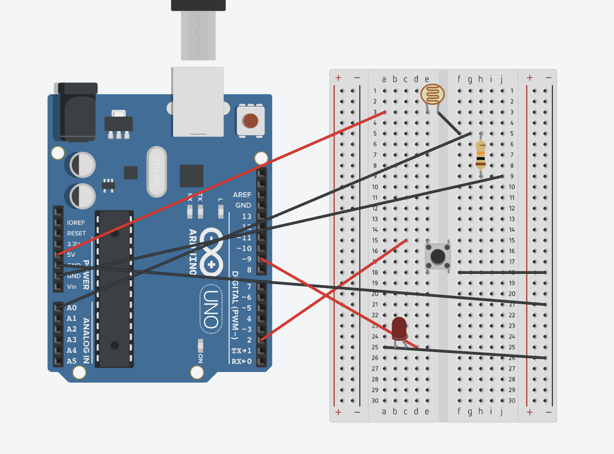
It is a simple schematic, where I use A0 to read the LDR values and then programmed so that it affect how the built-in LED(D13) changes accordingly.
Then I use D2 to read the switch status and change how the LED light would perform(D9).
Code:
if (value <= lightThreshold) {
    digitalWrite(ledPin, HIGH);   // Dark → LED ON
  } else {
    digitalWrite(ledPin, LOW);    // Bright → LED OFF
  }
This is the part of the code where I control the light based on the A0 values.
if (reading != lastButtonState) {
    lastDebounceTime = millis(); // reset timer if state changed
  }

  if ((millis() - lastDebounceTime) > debounceDelay) {
    // If the button is pressed (LOW because of INPUT_PULLUP)
    if (reading == LOW && lastButtonState == HIGH) {
      // Toggle LED state
      ledState = !ledState;
    }
  }
This i the part of the code that I apply to change the LED light status.
The lightThreshold value is determined by experimenting and printing out the A0 value when cover/uncover the LDR.
Serial.print("Light level: ");
Serial.println(value);
Reflection:
I still need more practice on connecting the board as I am not familiar with how to design the board to make the wiring more clean and beautiful. I also could come up with more creative idea on how to control the LED.