Concept:
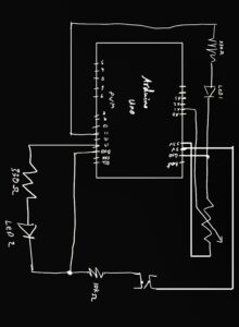
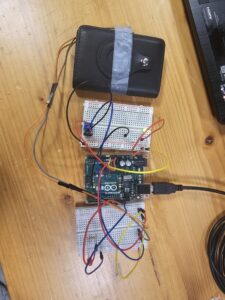
For this assignment, we were asked to control one LED in an analog manner and another in a digital manner. I chose to use a button switch to control one LED and a potentiometer for the other. For the digital component, I attached a button switch to my wallet’s card-ejection button so that whenever I try to access my credit card, a red LED lights up as a gentle warning to consider my spending. For the analog component, I connected a potentiometer to a blinking LED, allowing the speed of the LED’s blinking to be adjusted by turning the potentiometer. This setup demonstrates both analog and digital LED control in a creative, practical application.
Highlight:
A key highlight of this project is my approach to keeping the analog and digital circuits distinct from each other. By treating them as separate circuits, I chose to use the Arduino’s 5V and 3.3V power outputs individually powering the digital circuit with 5V and the analog circuit with 3.3V. Additionally, I set up each circuit on separate breadboards, which makes it easy to distinguish between the two and ensures a clear, organized layout. This setup not only reinforces the conceptual differences between analog and digital control but also simplifies troubleshooting and testing.

For the coding aspect of this project, I organized the code by designating separate blocks for the analog and digital controls, clearly separated by comments. This structure makes the code easier to navigate and understand, as each section is dedicated to controlling one LED independently.
In the blinking LED project, I utilized the map function, as we covered in class, to control the blinking speed with the potentiometer. By mapping the potentiometer’s analog input range (0–1023) to a delay range (e.g., 50–1000 milliseconds), I was able to adjust the blink rate based on the potentiometer’s position.
int led = 11;

void setup() {
 Serial.begin(9600);

 pinMode(led, OUTPUT);
 pinMode(13, OUTPUT);
 pinMode(A2, INPUT);

}

void loop() {
//controlling led with a potentiometer
    int sensorValue = analogRead(A1);
    Serial.println(sensorValue);

    // Map the potentiometer value (0–1023) to a delay time (e.g., 50–1000 ms)
    int blinkDelay = map(sensorValue, 0, 1023, 50, 1000);

    // Blink the LED at a speed controlled by the potentiometer
    digitalWrite(led, HIGH);
    delay(blinkDelay);
    digitalWrite(led, LOW);
    delay(blinkDelay);

//Controlling Led with a Button
int buttonState = digitalRead(A2);
if (buttonState == LOW) {
digitalWrite(13, LOW);
} else {
digitalWrite(13, HIGH);
}

}
Demonstration:
Digital Circuit
Analog Circuit

