
Here are pictures and videos of my unusual switch: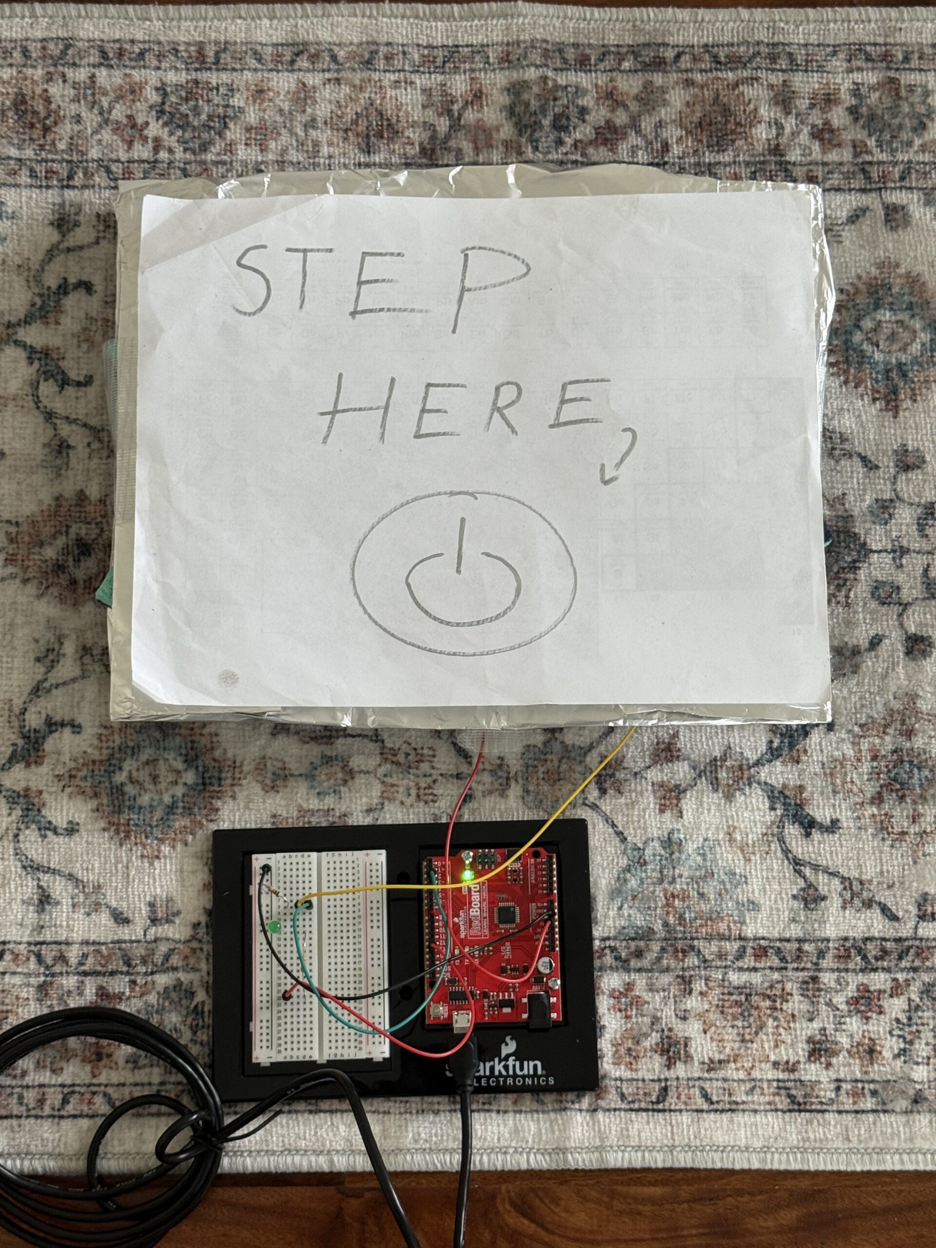
Video:
Here is the GitHub link to my code:
Overall concept
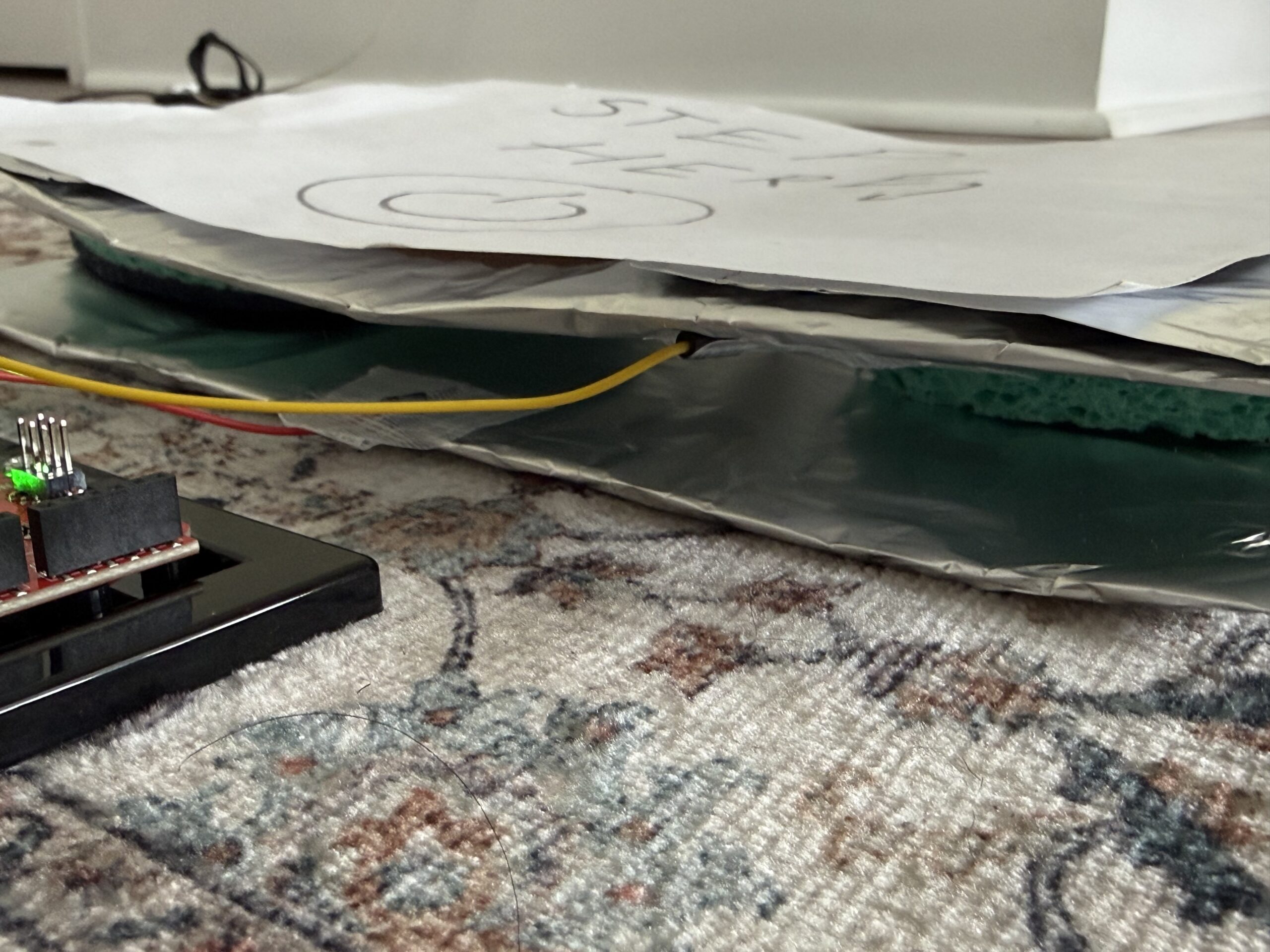
So for this project, I decided to create a foot-activated switch. When I press my foot on the pad I made with aluminium foil, tape, sponges, and cardboard, it completes the circuit and lights up the blinking LED. When I remove my foot, the LED turns off. I wanted something creative that uses the human body in a new way, and the foot switch, to me, felt unusual and fun to play with, even though it is a basic concept.
Code Highlight
The code that I am most proud of is the blinking effect. I wanted to incorporate it because we learned how to do it in class. I thought it wouldn’t be possible to put it in the if statement because I needed the light to turn off once you remove your foot. But by delaying it by 100 and turning the LED off and on quickly, it made a fast blinking effect when my foot presses the pad.
if (buttonState == HIGH) { //if the switch is pressed
digitalWrite (13,HIGH); //the LED turns on
delay(100); //cause a delay so I can produce a fast blinking effect
digitalWrite (13,LOW); //to turn the LED off for the blink effect
delay(100); //the fast delay to complete the blink full cycle
}
Reflection/Future work
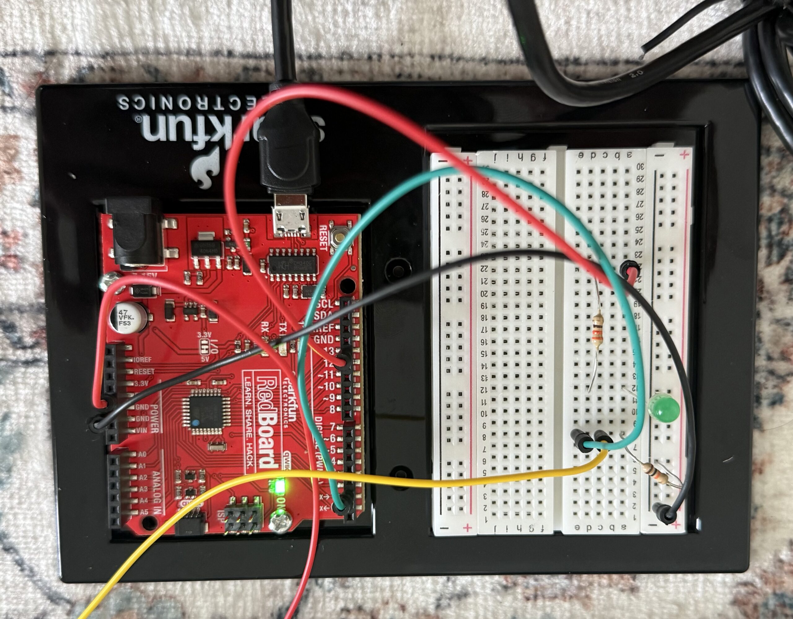
To build the circuit, I implemented basically the same thing we discussed in class. For the LED circuit, I connected pin 13 of the Arduino to a 330 resistor, which then connects to the long leg of the LED. The short leg of the LED connects to the ground row. For the switch circuit, I made a simple foot pad switch, which I took reference from a website. I used two pieces of aluminium foil on cardboard pieces, and in between them two sponges so I can easily turn it on and off. and separate the aluminium foils. One foil connects to 5V, and the other connects to pin 2. I also added a 10k resistor between pin 2 and ground. The resistor keeps the input stable when the pads aren’t pressed, so the Arduino doesn’t get floating values and burn out. I put the wires in specific rows on the breadboard. For example, the green wire goes from pin 2 to the row shared with the resistor and one foil pad. The yellow wire connects the other foil pad to the same row. This makes sure that when my foot presses the pads, pin 2 gets 5V, and when not pressed, the resistor pulls it down to 0V.
For future improvements, I would make the foot pad a bit more stable and try using multiple LEDs to make a pattern so the concept gets more creative. I would also experiment with different blink patterns to make it more interesting.
Here is the website I took inspiration from to make the pressure board:
https://www.instructables.com/Pressure-Switch-for-Makey-Makey/
Here is the sketch of my board and circuit connection diagram:
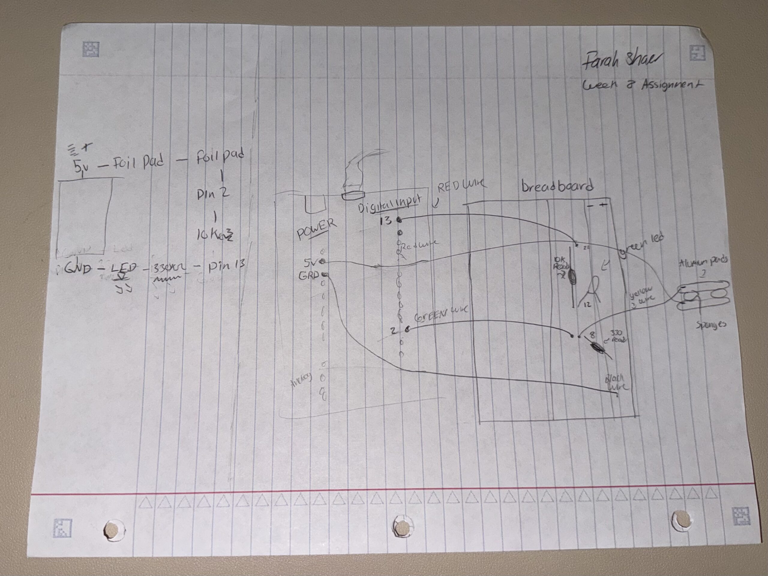
(I apologise for the quality of this sketch; I do not have any printer paper or markers yet.)