Week 9: Analog and Digital Sensors

Concept

For this week’s assignment, my overall concept is pretty similar to the one I did last week because it also has something to do with sleep. This time, I created a light system: for the first one, I used a button to turn on a single LED manually, and for the second one, the yellow LED turns on when the lights are turned off, just like a night light! I got inspiration for this idea from my little sister when we were kids, because she always used to sleep with a night light on.

Code
int buttonPin = 8;
int greenLED = 7;  // pin for green LED
int lightSensorPin = A2;
int yellowLED = 6;  // pin for yellow LED

void setup() {
  Serial.begin(9600);
  pinMode(buttonPin, INPUT_PULLUP);  
  pinMode(greenLED, OUTPUT);
  pinMode(yellowLED, OUTPUT);
}

void loop() {
  int sensorValue = analogRead(lightSensorPin);
  Serial.println(sensorValue);  // prints sensor value from light sensor

  if (digitalRead(buttonPin) == LOW) {  // button pressed
    digitalWrite(greenLED, HIGH);
  } else {
    digitalWrite(greenLED, LOW);
  }

  if (sensorValue < 175) {
    digitalWrite(yellowLED, HIGH);
  } else {
    digitalWrite(yellowLED, LOW);
  }
}

So basically, I used conditional statements for when I wanted each LED to turn on. The green LED was connected to the digital pins, so I used a button to turn it on and off: when the button is pressed, the LED lights up, and when it’s not pressed, the LED turns off. For the yellow LED, it checks the light sensor’s value, and when that value goes below 175, the LED turns on (so when the lights are off, the yellow LED acts as a night light!).

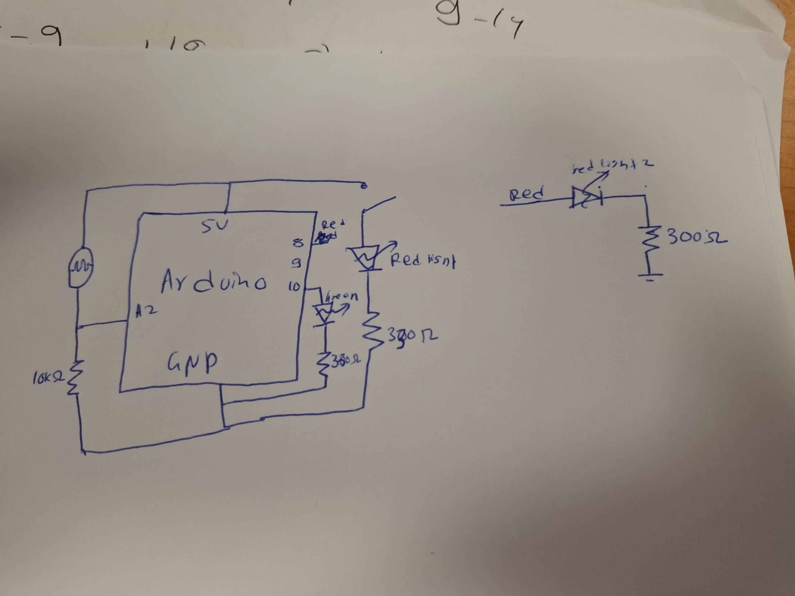
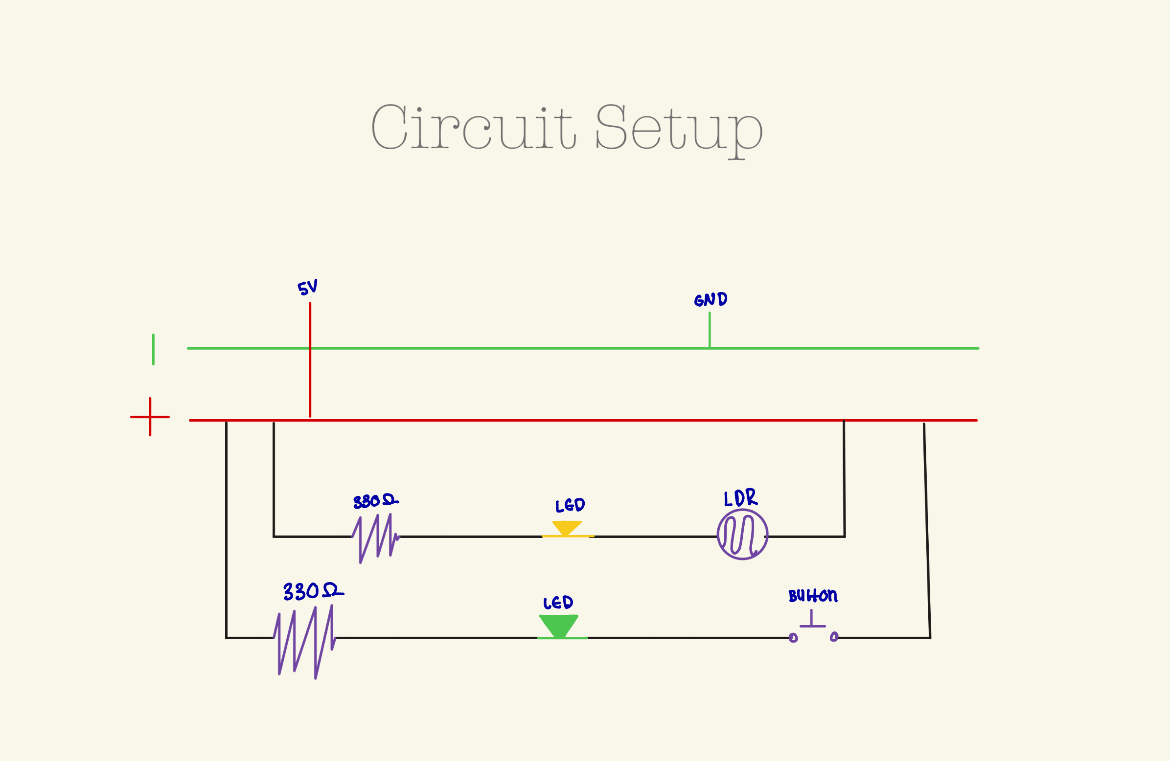
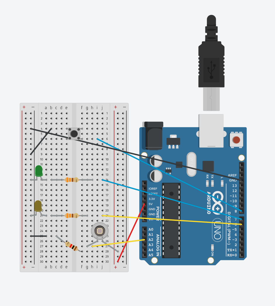
Hand-Drawn Schematic
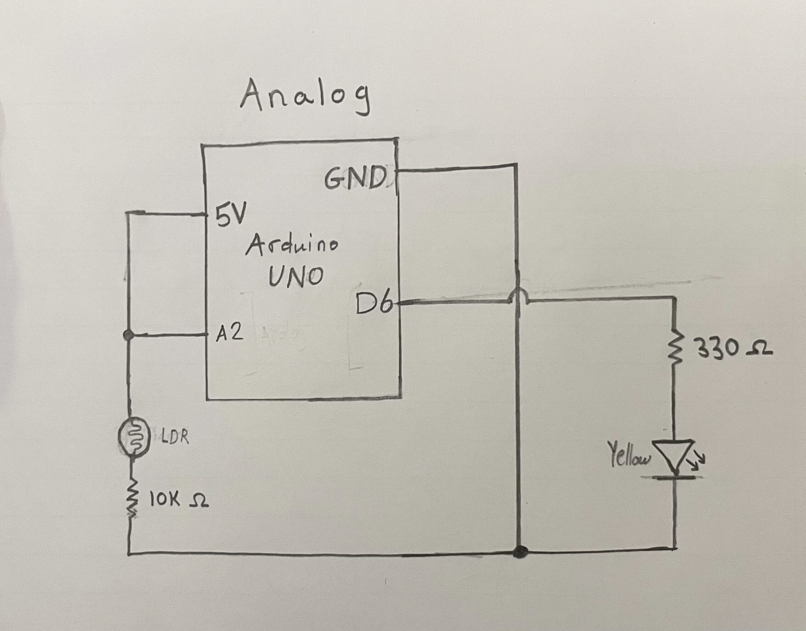
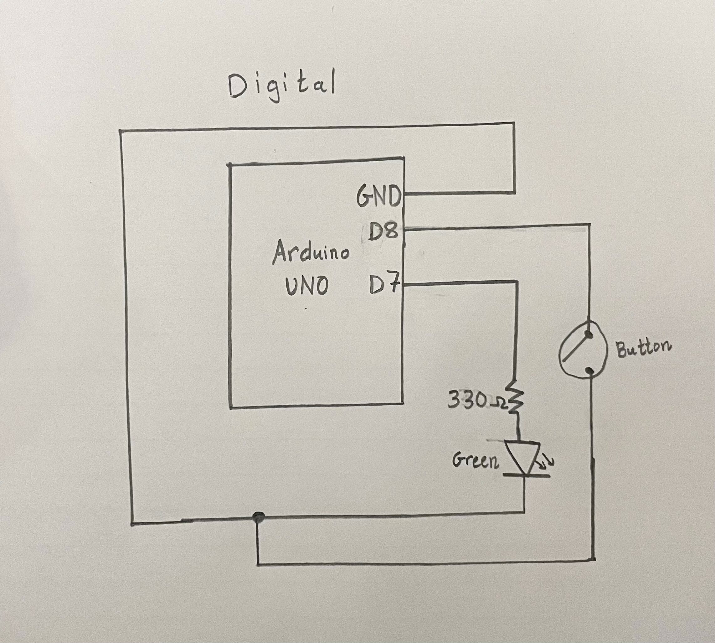
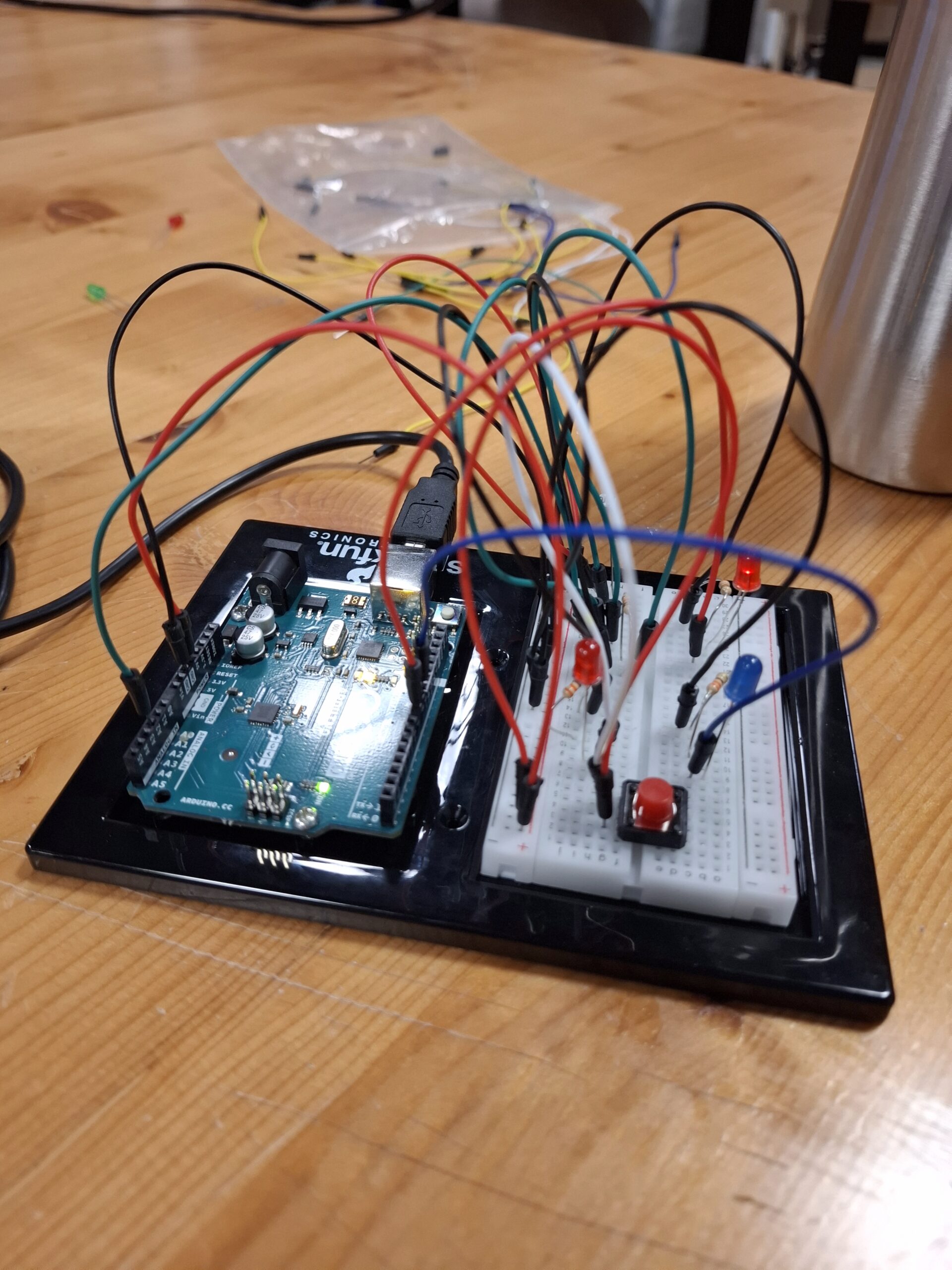
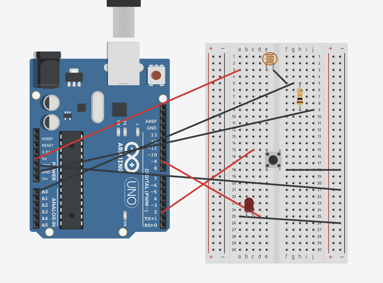
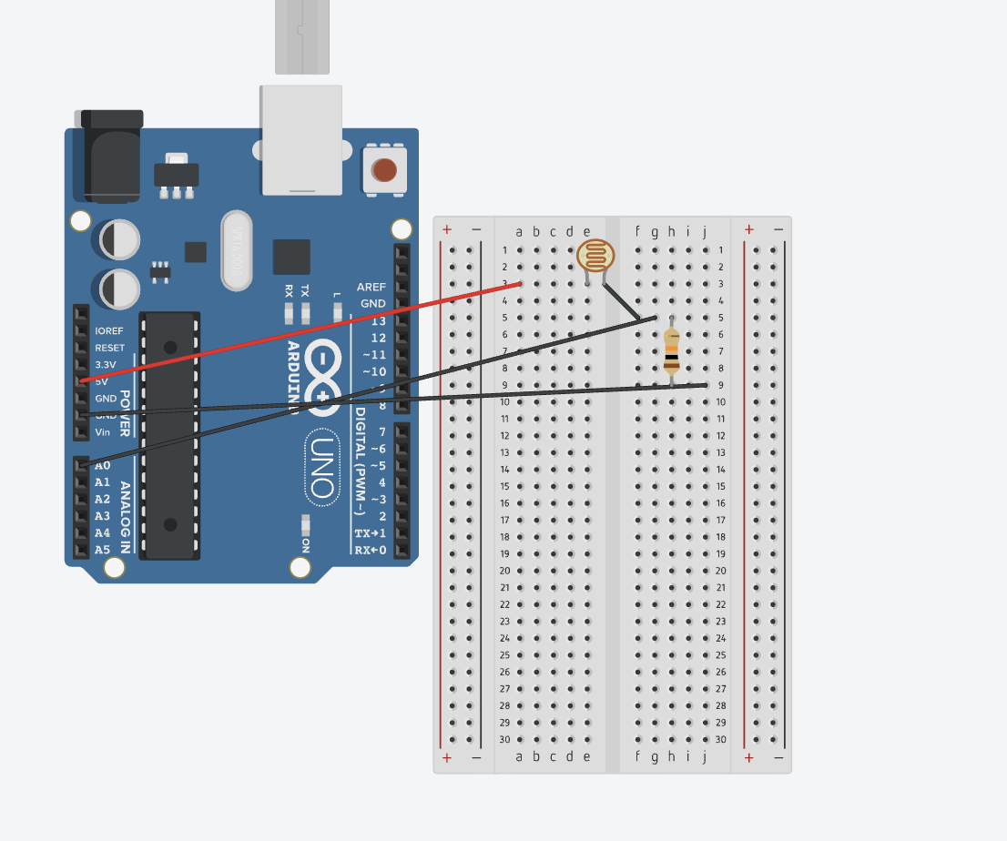
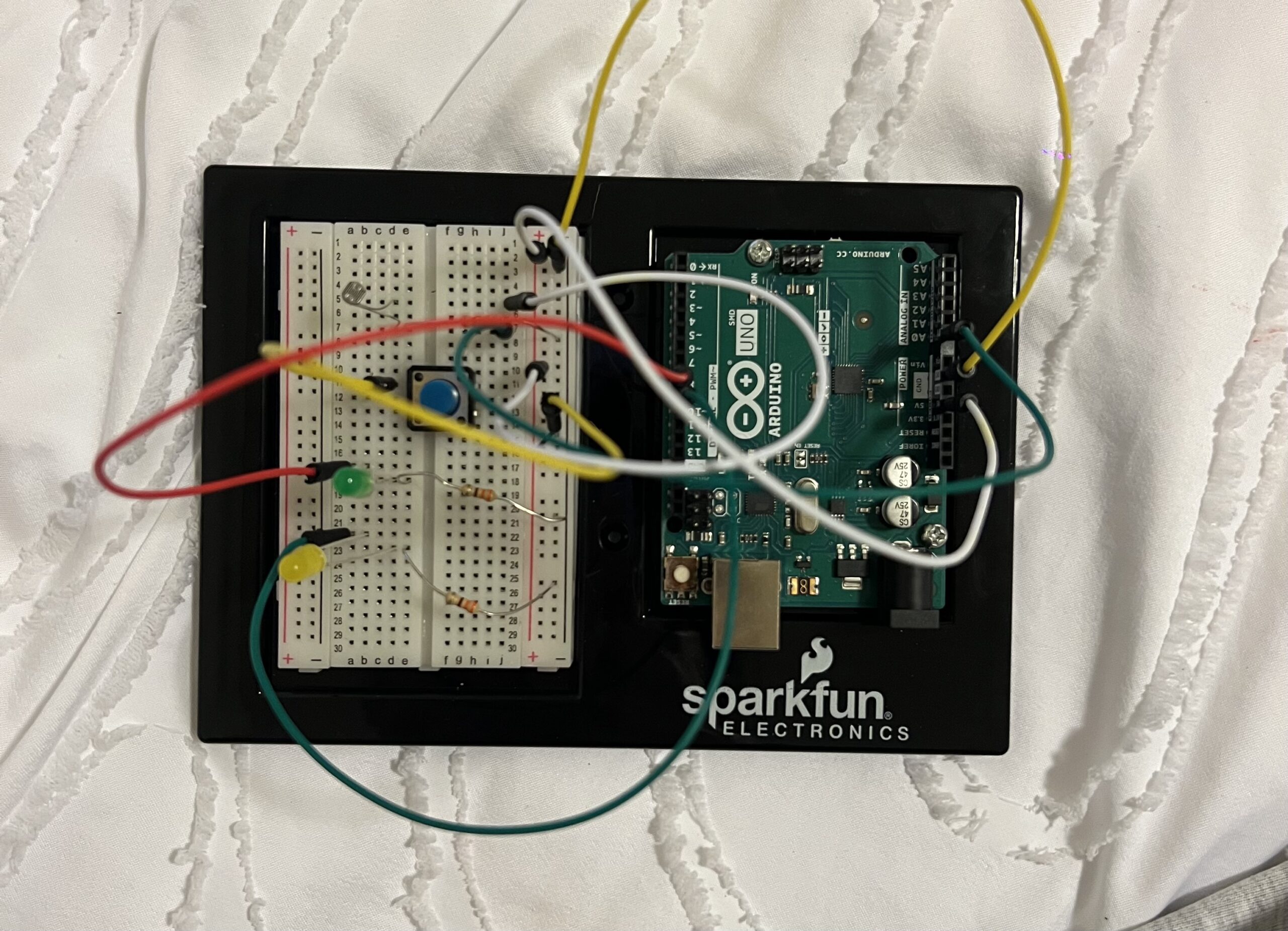
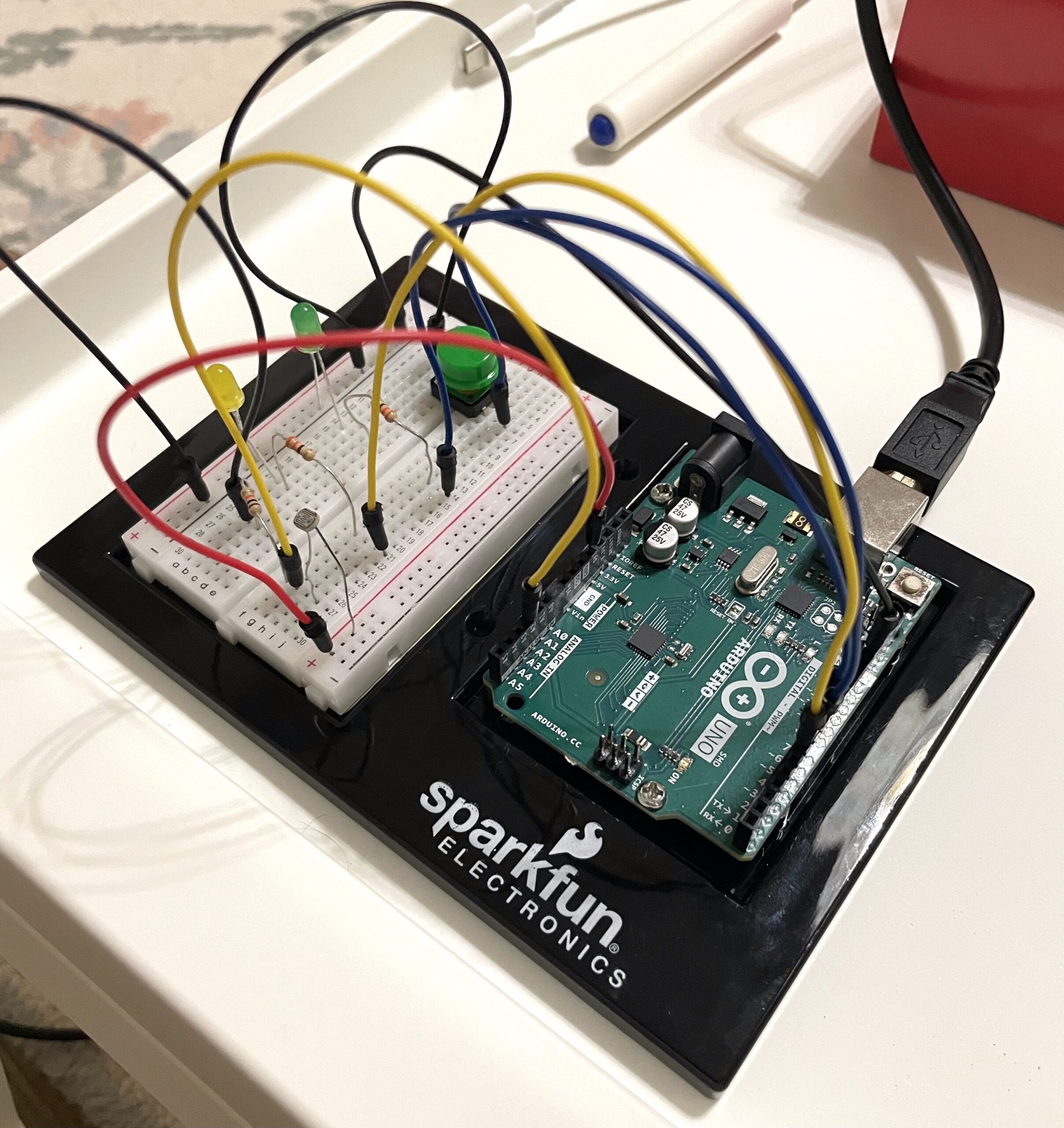
Schematic diagram and Photo:
Video Demo
Reflection and Future Improvements

Honestly, it was pretty hard to come up with a concept for this project, but when I did, I’m satisfied with how it turned out. Another thing was that I underestimated how much time this would take, it took me way too long to figure everything out and fix the issues on the circuit. In the future, I plan on practicing wiring more often and getting a better understanding of circuit logic.

Week 9: Physical Computing’s Greatest Hits (and misses)

Reading Tom Igoe’s Physical Computing’s Greatest Hits (and Misses) made me think about how creative patterns tend to repeat, especially in hands-on, tech-driven projects. Igoe doesn’t frame repetition as a lack of originality, which I appreciated. Instead, he treats these recurring themes—like theremin-like instruments, drum gloves, or video mirrors—as open-ended ideas that people keep revisiting because they’re fun, expressive, and adaptable. I related to that idea a lot because I’ve definitely hesitated before, thinking something wasn’t worth doing since it had “been done before.” But the more I read, the more I agreed with his point that originality isn’t about inventing from scratch; it’s about finding your own way into an existing form. What stood out to me were the projects that relied on the body as the main input—like gloves that create rhythm through tapping or instruments that react to gestures. Those projects feel personal and direct, and I like how they blend instinct with technology. Igoe’s descriptions made me realize that the best physical computing ideas don’t just respond to touch or movement; they build a relationship with the person using them.

Some parts of the reading also made me laugh or nod along because I’ve seen those same trends pop up in classes or exhibits. The “video mirrors,” for instance, are always visually striking but usually shallow in interaction—you wave, something moves, and that’s it. Igoe’s critique there made sense. It reminded me that while technology can catch attention, meaning comes from how people connect to it, not just how it looks. I was also drawn to the more poetic examples like “Mechanical Pixels” or “Fields of Grass,” where simple mechanisms create quiet, almost meditative experiences. Those pieces blur the line between machine and nature, which I find really compelling. Even the sillier categories, like “Things You Yell At,” showed how emotional interaction can be when it’s physical and immediate. Overall, the article made me think about how I might approach projects differently: not trying to avoid what’s been done, but trying to make it feel a bit more like me.

Week 9: Reading Response


Physical Computing’s Greatest hits and misses

When I read Physical Computing’s Greatest Hits (and Misses) by Tom Igoe, I found it fascinating how creativity often repeats itself, not out of laziness, but because some ideas are simply too human to let go of. Whether it’s waving your hand to make music like a theremin, or building dancing floor pads inspired by Dance Dance Revolution, these projects remind me that interaction is a language our bodies already know.

Igoe’s writing made me realize that physical computing isn’t just about wiring sensors or programming microcontrollers. It’s about finding meaning in movement and connection. His examples like gloves that make drum sounds or video mirrors that reflect your gestures  all blur the line between play and design. I like how he admits that some of these projects are “pretty but shallow.” It’s honest. It’s easy to get lost in flashing LEDs and forget to ask: what experience am I creating for the user?

The part that stayed with me most was his reminder that originality doesn’t mean doing something no one’s ever done before  it means doing something familiar in a new way. That’s comforting. As someone who’s just learning, I often feel like my ideas are too simple or already “done.” But after reading this, I see that even a basic project, a light sensor or a glove, can become unique if I bring my own perspective, story, or purpose to it.

Making Interactive Art: Set the Stage, Then Shut Up and Listen

When I was reading Tom Igoe’s Making Interactive Art: Set the Stage, Then Shut Up and Listen, I was struck by how simple yet challenging his message was. He tells artists and creators to stop explaining their own work  to resist the urge to direct, interpret, or control what others should feel. It’s funny how that sounds easy, but for anyone who’s ever made something personal, it’s actually the hardest thing to do. We want to be understood. We want people to “get it.”

Igoe reminds us that interactive art isn’t about showing, it’s about inviting. The artist’s job is not to tell a story, but to create a space where others can find their own. When he says, “Once you’ve built it, shut up,” it hit me like a creative reality check. In most traditional art forms painting, photography, sculpture  the work speaks through form and color. But with interactive art, the audience literally completes the piece through their movement, curiosity, and touch. That’s terrifying and beautiful at the same time.

I also loved how Igoe compares designing interaction to directing actors. You can’t tell an actor how to feel; you just set the stage, give them a prop, and trust that they’ll find emotion in the act itself. That idea applies perfectly to physical computing and interactive design. The best projects don’t just respond to people  they encourage discovery. They leave space for mistakes, surprises, and personal interpretation.

Reading this made me think differently about my own work. I realized that in some of my projects, I’ve tried to control the experience too tightly giving too many instructions or forcing a specific reaction. But now, I see that a good interactive project is a conversation, not a lecture. It listens as much as it speaks.

Week 9: Smart Pedestrian Light System

Concept:

In my home town, we don’t usually have automatic traffic lights for pedestrian (zebra) crossings. When I came to the UAE, I found it really interesting that many crossings have a touch-sensitive button on the pole, when a pedestrian presses it, the system detects the request and changes the traffic light to red for vehicles, allowing people to cross safely.

263 Abu Dhabi Road Signs Stock Video Footage - 4K and HD Video Clips | Shutterstock

I wanted to mimic that concept using simple electronic components. In my prototype, a light sensor (LDR) acts as the pedestrian touch detector. When I place my finger over the sensor,  “green” light turns on (in my case, a blue LED, since my green ones were damaged), signaling that a pedestrian wants to cross. When the sensor is not covered, meaning the LDR value stays above a certain threshold (around 400), it represents that no one is waiting to cross, so the “red” light for pedestrians remains on.

Additionally, I included a digital switch that simulates a traffic officer controlling the lights manually. Whey they clicked the red button, red light turns on and force they vehicle to stop.

Video:


Code:

const int LDR= A2;
const int LDR_LED=10;
const int red_LDR=8;
void setup() {
  // put your setup code here, to run once:

  Serial.begin(9600);
}

void loop() {
  // put your main code here, to run repeatedly:
  int value= analogRead(LDR);
  Serial.println(value);
   
  if(value<=500){
    digitalWrite(LDR_LED,HIGH);
    Serial.println("yes");
   
    digitalWrite(red_LDR,LOW);
   
  }
  else{
    digitalWrite(LDR_LED,LOW);
    digitalWrite(red_LDR,HIGH);
  }
  
}


Schematics:

W9: Assignment

Concept

Parking lots can often be a frustrating experience, especially when it’s hard to tell whether a spot is free or occupied without driving around aimlessly. I wanted to create a simple, interactive system using Arduino that mimics real-world parking indicators: a yellow light that changes brightness when a car is moving in or out, and a red light that turns on when a spot is occupied. This way, drivers can quickly see which spots are available and which are taken, making the parking process smoother and more intuitive.

Implementation

To achieve this, I used an ultrasonic sensor to detect the movement of cars. The sensor works by sending out a pulse from the trigger pin, which bounces off an object and returns to the echo pin. The Arduino then calculates the distance based on the time it takes for the pulse to return. I mapped this distance to the brightness of a yellow LED, so that the closer a car gets to the parking spot, the brighter the yellow light becomes. A slide switch allows us to manually indicate when a car is parked: flipping the switch turns on a red LED and turns off the yellow light, clearly showing that the spot is occupied. Two 330-ohm resistors ensure the LEDs operate safely without drawing too much current.

cardemo

Code I’m proud of

// Trigger pulse 
digitalWrite(trigPin, LOW);
delayMicroseconds(2);
digitalWrite(trigPin, HIGH);
delayMicroseconds(10);digitalWrite(trigPin, LOW);

// Read echo
duration = pulseIn(echoPin, HIGH);
distance = duration * 0.0343 / 2.0;

I’m particularly proud of the code I wrote for this project. Writing it taught me a lot about how ultrasonic sensors work and how to use the trigger and echo functionality effectively.

Future Developments

For future development, the system could be expanded to include a green LED, which would light up to indicate available parking spots. In that scenario, the green light would show availability, the yellow LED would indicate movement, and the red LED would signal when a spot is taken. Eventually, this could be automated further so that the sensor alone detects whether a car is parked, eliminating the need for the manual switch. Overall, this project was a great exercise in combining sensors, outputs, and user interaction to create a functional and visually intuitive system.

Week 9 Two Switches

Idea:

Since the problem is to create two types of control, I already created a switch using the idea to use photoresistor to control the circuit. I will just apply the other switch with basic switching on/off control.

Schematic:


It is a simple schematic, where I use A0 to read the LDR values and then programmed so that it affect how the built-in LED(D13) changes accordingly.

Then I use D2 to read the switch status and change how the LED light would perform(D9).

Code:

if (value <= lightThreshold) {
    digitalWrite(ledPin, HIGH);   // Dark → LED ON
  } else {
    digitalWrite(ledPin, LOW);    // Bright → LED OFF
  }

This is the part of the code where I control the light based on the A0 values.


if (reading != lastButtonState) {
    lastDebounceTime = millis(); // reset timer if state changed
  }

  if ((millis() - lastDebounceTime) > debounceDelay) {
    // If the button is pressed (LOW because of INPUT_PULLUP)
    if (reading == LOW && lastButtonState == HIGH) {
      // Toggle LED state
      ledState = !ledState;
    }
  }

This i the part of the code that I apply to change the LED light status.

The lightThreshold value is determined by experimenting and printing out the A0 value when cover/uncover the LDR.

Serial.print("Light level: ");
Serial.println(value);


Reflection:

I still need more practice on connecting the board as I am not familiar with how to design the board to make the wiring more clean and beautiful. I also could come up with more creative idea on how to control the LED.

Week 8 Unusual Switch

Idea:

Since the problem is prompted to create a switch that should use the human body (but not the hands), I instantly come up with the idea to use photoresistor to control the circuit. As photoresistor reacts to the light intensity, basically you could use any body part to control the system as long as it cover/uncover the photoresistor.

Schematic:

It is a simple schematic, where I use A0 to read the LDR values and then programmed so that it affect how the built-in LED(D13) changes accordingly.

Code:

if (value <= lightThreshold) {
    digitalWrite(ledPin, HIGH);   // Dark → LED ON
  } else {
    digitalWrite(ledPin, LOW);    // Bright → LED OFF
  }

This is the part of the code where I control the light based on the A0 values.

The lightThreshold value is determined by experimenting and printing out the A0 value when cover/uncover the LDR.

Serial.print("Light level: ");
Serial.println(value);


Reflection:

It took me longer than expected to complete this as I am not familiar enough with working with the board. Nonetheless, it is a fun experience experimenting with both the hardware and the software at the same time. Future improvements would center around controlling other than built-in LEDs and improving the circuit design.

Week 9 assignment

For this assignment, I decided to use the potentiometer and the button. I wanted the potentiometer to control how bright the RGB light is and use the switch button for 2 purposes, to change the general colour of the RGB but to also start and stop the blinking of the red alarm LED I used.

I had the code use 4 different colours but have this also a factor on how many blinks occur with the LED light.

I had the switch button be used as a way to have the red LED on or off.

To be honest, I used the Claude Sonnet 4..5 model to give me ideas on how I can make the whole system more interesting / creative. That is how the idea of having the number of pings be dependent on the colour came from.

this is the code I used

// PIN location
const int POT_PIN = A0;           // Potentiometer
const int BUTTON_PIN = 2;         // Push button 
const int RGB_RED_PIN = 9;        
const int RGB_GREEN_PIN = 10;     
const int RGB_BLUE_PIN = 11;      
const int MODE_LED_PIN = 13;      // Ree LED 

int potValue = 0;                 
int brightness = 0;               
bool buttonState = false;         
bool lastButtonState = false;     
int colorMode = 0;               
unsigned long previousMillis = 0; //  non-blocking blink timing
const long blinkInterval = 150;   // blink interval for mode indicator
bool modeLedState = false;        

const char* modeNames[] = {"White", "Red", "Green", "Blue"};

void setup() {
  Serial.begin(9600);
  
  // set pins
  pinMode(POT_PIN, INPUT);
  pinMode(BUTTON_PIN, INPUT);
  pinMode(RGB_RED_PIN, OUTPUT);
  pinMode(RGB_GREEN_PIN, OUTPUT);
  pinMode(RGB_BLUE_PIN, OUTPUT);
  pinMode(MODE_LED_PIN, OUTPUT);
  
  // initialise LEDs as off
  analogWrite(RGB_RED_PIN, 0);
  analogWrite(RGB_GREEN_PIN, 0);
  analogWrite(RGB_BLUE_PIN, 0);
  digitalWrite(MODE_LED_PIN, LOW);
}

void loop() {
  // potentiometer read
  potValue = analogRead(POT_PIN);
  
  // map the values of the potentiometer to a brightness value
  brightness = map(potValue, 0, 1023, 0, 255);
  
  // button read
  buttonState = digitalRead(BUTTON_PIN);
  
  // when button is pressed, change the colour
  if (buttonState == HIGH && lastButtonState == LOW) {
    colorMode = (colorMode + 1) % 4;  //cycle through 0-3
    Serial.println(modeNames[colorMode]);
    delay(50);  
  }
  
  lastButtonState = buttonState;
  
  // change RGB LED based on selected colour
  switch(colorMode) {
    case 0:  //  white
      analogWrite(RGB_RED_PIN, brightness);
      analogWrite(RGB_GREEN_PIN, brightness * 0.8); 
      analogWrite(RGB_BLUE_PIN, brightness * 0.6);  
      break;
      
    case 1:  // red 
      analogWrite(RGB_RED_PIN, brightness);
      analogWrite(RGB_GREEN_PIN, 0);
      analogWrite(RGB_BLUE_PIN, 0);
      break;
      
    case 2:  // green 
      analogWrite(RGB_RED_PIN, 0);
      analogWrite(RGB_GREEN_PIN, brightness);
      analogWrite(RGB_BLUE_PIN, 0);
      break;
      
    case 3:  // blue 
      analogWrite(RGB_RED_PIN, 0);
      analogWrite(RGB_GREEN_PIN, 0);
      analogWrite(RGB_BLUE_PIN, brightness);
      break;
  }
  
  // Mode 0 = no blinks (off)
  // Mode 1 = 1 blink
  // Mode 2 = 2 blinks 
  // Mode 3 = 3 blinks
  handleModeIndicator();
  delay(10);  // Small delay for stability
}

//function to handle the 
void handleModeIndicator() {
  unsigned long currentMillis = millis();
  static int blinkCount = 0;
  static unsigned long patternStartTime = 0;
  static bool isBlinking = false;
  
  // when white, keep LED off
  if (colorMode == 0) {
    digitalWrite(MODE_LED_PIN, LOW);
    blinkCount = 0;
    isBlinking = false;
    return;
  }
  
  // new blink pattern every 2 seconds
  if (!isBlinking && (currentMillis - patternStartTime >= 2000)) {
    isBlinking = true;
    blinkCount = 0;
    patternStartTime = currentMillis;
  }
  
  // perform blinks equal to color mode number
  if (isBlinking) {
    unsigned long timeInPattern = currentMillis - patternStartTime;
    int currentBlink = timeInPattern / (blinkInterval * 2);  // *2 for on+off
    
    if (currentBlink < colorMode) {
      // still within the blink count for this mode
      unsigned long timeInBlink = timeInPattern % (blinkInterval * 2);
      
      if (timeInBlink < blinkInterval) {
        digitalWrite(MODE_LED_PIN, HIGH);  // LED on
      } else {
        digitalWrite(MODE_LED_PIN, LOW);   // LED off
      }
    } else {
      digitalWrite(MODE_LED_PIN, LOW);
      isBlinking = false;
    }
  }
}


IMG_2228


Week 9 — Reading Response

Reflection on “Physical Computing’s Greatest Hits (and Misses)”

What really stood out to me in this reading was how the author said that even if an idea has been done before, you can still make it your own. I really liked that because it’s true that’s what innovation is about. You don’t have to come up with something completely out of nowhere; you can take inspiration from something that already exists and build on it in a new, creative way. I think that’s how creativity actually grows. You start with something familiar, but through your own thinking and style, it becomes something unique. This really reminded me of when I used to take AP Art. At first, I had no idea what I wanted to do for my project. Then I saw one of my sister’s artworks that explored the theme of identity, and it completely inspired me. I didn’t copy her work, but that idea sparked something in me. From that one starting point, I was able to create five very different artworks that still connected to the same concept but were completely my own. That’s why I loved how the author talked about using old ideas as a base because it’s not about repeating; it’s about reimagining.

I also liked what he said about human interaction versus machine automation. Physical computing isn’t just about building a machine that runs on its own; it’s about creating something that responds to people that comes to life when you interact with it. It makes technology feel more alive, more connected to us as humans. It’s the same reason interactive things have always felt more exciting to me. Even when I was a kid, I loved books that had textures you could feel or pop-up pages that moved when you turned them. They were so much more fun and engaging than flat, ordinary books. It’s the same in learning, too when a class is just lecture-based, it’s hard to stay focused. But when you get to dosomething, to interact with it, you remember it better. It becomes real. So, I think that’s what makes physical computing so special  it brings art, design, and technology together in a way that feels alive. It reminds us that interaction, whether through touch, movement, or emotion, is what truly connects us to what we create.

Reflection On  “Making Interactive Art: Set the Stage, Then Shut Up and Listen”

I really liked how this reading talks about giving people the space to experience and interpret art on their own. It makes the artwork feel alive because the audience becomes part of it they create their own meaning instead of just being told what to think. That’s what makes interactive art special; it’s an experience, not just something to look at. It also reminds me of modern art, where there isn’t always one fixed meaning. Everyone can see it differently, and that’s what keeps it interesting. When you explain everything, it becomes dull and predictable, but when you leave room for imagination, it feels more human and engaging.

I’ve been taking this in my first-year writing seminar, where we’ve been learning about how different people view art and meaning. Anish Kapoor, who is a really famous and worldwide-known artist, once said, “The work itself has a complete circle of meaning and counterpoint. And without your involvement as a viewer, there is no story.” I think that perfectly connects to what this reading talks about the idea that art isn’t something that should explain itself to you, but something you experience and find meaning in yourself. Kapoor’s artworks don’t have one fixed meaning; instead, they give space for the viewer to create it. That’s what makes his art so powerful and interactive. Homi Bhabha also says, “It is the in-between space that carries the burden of the meaning of culture,” which I think means that real meaning is found in that space between the artwork and the person experiencing it. So the beauty of Kapoor’s work and interactive art in general is that it doesn’t just lack meaning; it creates room for meaning.

Week 9 — Analog and Digital Sensors


The Planning Process

When I first started working on my Arduino project, I was really excited to just begin building the circuit. I started connecting the wires and components right away without any plan, but everything quickly got messy. The setup didn’t look neat, and nothing was working properly.

That’s when I decided to stop and make a clear plan. I drew a circuit sketch first, showing where every wire, resistor, LED, and sensor would go. Having that plan made a huge difference it helped me organize everything and made the setup much cleaner and easier to follow.

I realized that starting with a plan is the foundation of any successful Arduino project. Without it, things can get confusing fast. But when you have a sketch or diagram to look back at while you’re working, you always know what to do next. This experience really taught me that planning first saves a lot of time and makes the whole process smoother and more enjoyable.

Arduino Setup

This setup was a little complicated for me because it was my first time doing something more advanced on the Arduino that involved several wires and components. I used about seven different wires, and at first, it was really confusing to figure out where everything should go.

At the beginning, when I tried building the circuit without any plan, it turned into a big mess and nothing worked properly. But after creating a proper plan and sketch, everything became so much clearer. I started connecting each part slowly and carefully, double checking as I went along.

Sometimes I made small mistakes, like connecting the long leg of the LED to the resistor instead of the correct side, but having the plan helped me find and fix them easily. I realized how important it is to work precisely and patiently, making sure each wire is placed in the right spot before moving on.

Overall, the planning process made the project much easier and more enjoyable. I also liked that my circuit included two different sensors a button (digital sensor) and an LDR (Light Dependent Resistor), which is an analog sensor with a squiggly pattern on top. It was really cool to see how both types of sensors could work together in one project.

Coding Process

// Pin setup 
const int buttonPin = 2;   // Button connected to D2 
const int ledDigital = 8;  // Digital LED (on/off)
const int ledAnalog = 9;   // Analog LED (brightness control)
const int ldrPin = A0;     // LDR sensor connected to A0

void setup() {
  pinMode(buttonPin, INPUT_PULLUP); 
  pinMode(ledDigital, OUTPUT);
  pinMode(ledAnalog, OUTPUT);
}

void loop() {
  // Digital LED controlled by button 
  bool pressed = (digitalRead(buttonPin) == LOW); // LOW = pressed
  digitalWrite(ledDigital, pressed ? HIGH : LOW);

  // Analog LED controlled by LDR light level 
  int lightValue = analogRead(ldrPin);        // Reads LDR 
  int brightness = map(lightValue, 0, 1023, 0, 255); 
  analogWrite(ledAnalog, brightness);         // Set LED brightness

  delay(10); 
}

I really liked the simplicity of the code in this project. The Arduino part allowed me to be more creative with how I connected the components, but the coding felt more like solving a puzzle. I just had to match everything correctly each sensor, LED, and button had its own number, and I connected them in the code like putting puzzle pieces together.

What I enjoyed most was how logical the coding process was. Once I understood how each part worked, everything made sense and came together smoothly. The code itself was clear and easy to follow, and the only thing I really had to play around with was the numbers to get the behavior I wanted. Overall, it was a really satisfying and smooth experience seeing the hardware and code work perfectly together.

Blink Test

Before starting my main circuit, I first tried the Blink Test, which is the simplest Arduino program that makes an LED turn on and off. It helped me confirm that my Arduino board was connected properly and that the code could upload successfully. Even though it’s a very basic test, it gave me confidence that everything was working before I started adding more components and sensors. It also helped me understand how timing and digital outputs work in Arduino.