Final Project Proposal & Progress Update

Concept

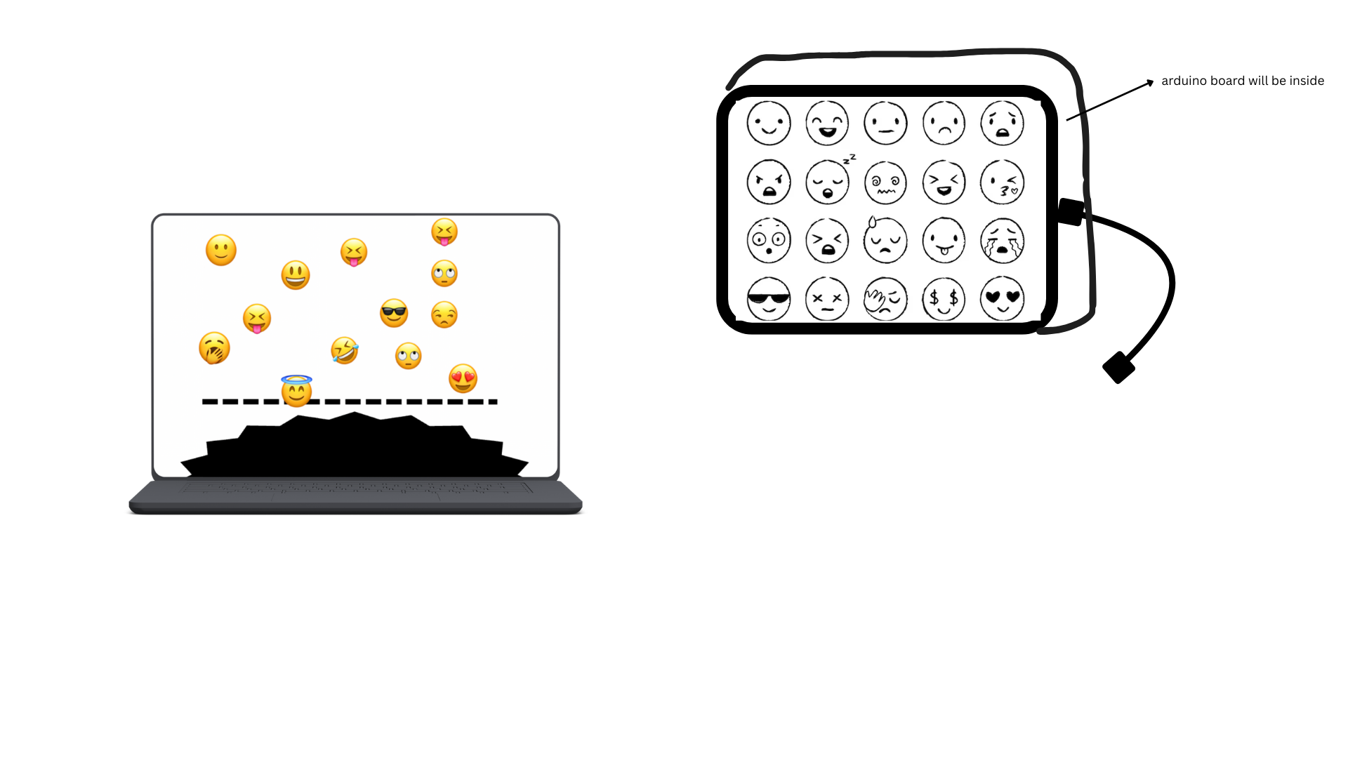
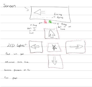
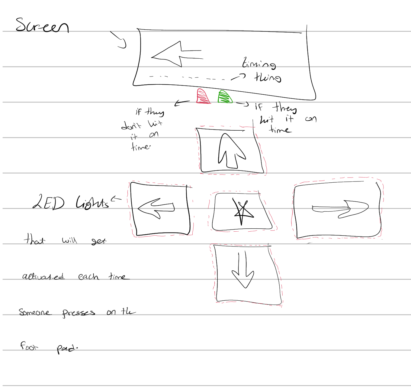
For my final project, I am creating Foot Loose, a physically interactive rhythm game where players step on large acrylic pads to hit falling arrows displayed on screen. The game draws inspiration from Dance Dance Revolution but is redesigned for the IM Fair using Arduino-based sensing, p5.js animation, and a layered LED feedback system.

The interaction is simple and energetic:

  • If the player steps at the correct moment, the system flashes a green LED beside the screen.

  • If the player’s timing is off, a red LED flashes instead.

This creates clear, readable, immediate feedback that works even in a crowded fair environment.

Each stepping pad will also have its own small, colorful LED taped beside it, lighting up the moment the player presses down. This pad-level LED provides instant, physical confirmation of the step before p5 even evaluates the timing. Together, the pad LEDs + the red/green judgment LEDs create a layered, intuitive communication system:

  • Pad LEDs → confirm the user physically stepped

  • Screen & red/green LEDs → confirm whether the timing was good or missed

The design makes the interaction active, performative, and easy for anyone to understand. Players use their whole body—not just their hands—to interact with the system.

System Overview

Foot Loose is built around a tight, responsive interaction loop:

Arduino LISTENS

Reads piezo sensors under the pads and detects steps.

p5.js THINKS

Controls the falling arrows, checks timing, displays visuals, and decides GOOD or MISS.

Arduino SPEAKS BACK

Flashes LEDs based on p5’s decision, creating physical feedback.

This two-way communication keeps players grounded in both the physical dance pads and the on-screen rhythm.


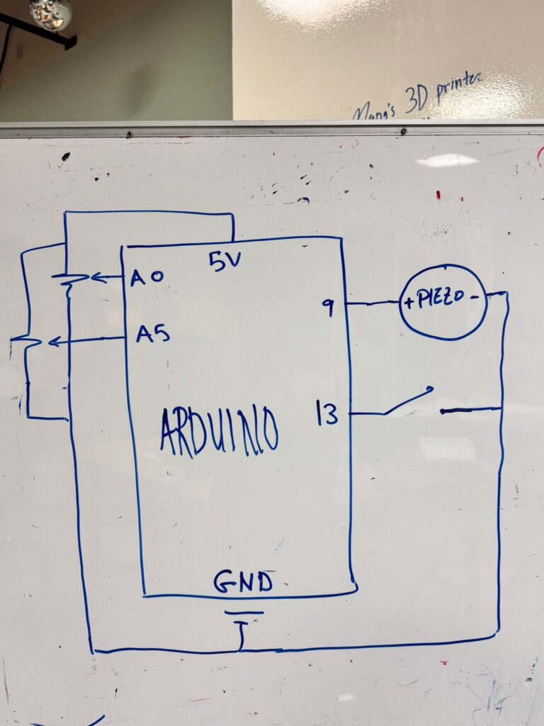
Arduino Design (Inputs, Outputs, Behavior)

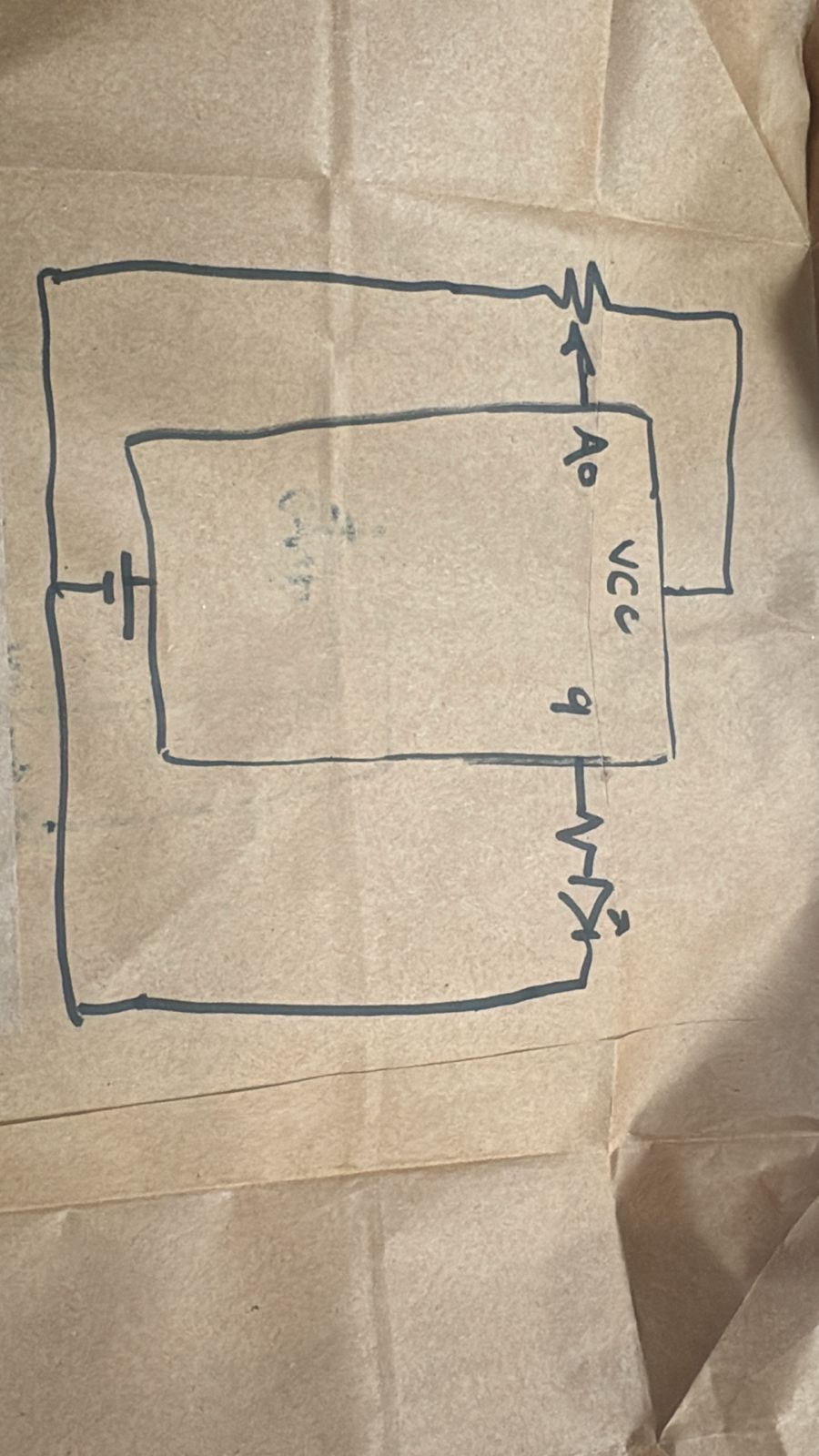
Inputs: Piezo Sensors Under Each Pad

Each stepping pad will contain a piezo sensor mounted underneath the acrylic.
To stabilize signals, every piezo uses a 1MΩ resistor.

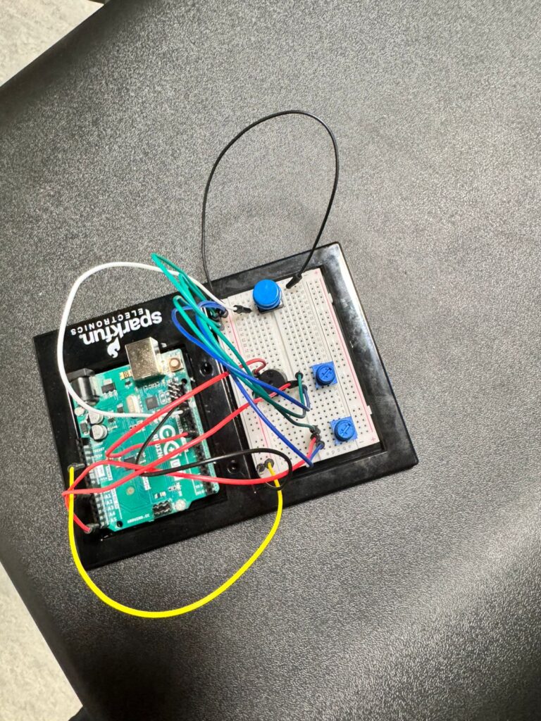
This week, I successfully prototyped the sensing system using:

  • A single piezo

  • Folded tissue padding

  • A hardcover book as a temporary “stepping pad”

Idle readings were stable, and step readings spiked clearly.
Arduino sends a simple message for every detected step:

“L”

Later on, each pad will have its own letter (e.g., L, R, U, D, C).

Outputs: LED Feedback (Two Types)

1. Pad-Level LEDs (instant physical confirmation)

Each pad has a small LED that lights up the moment the user steps on it.
These LEDs make the pads feel “alive” and give instant tactile feedback.

2. Main Feedback LEDs (green = GOOD, red = MISS)

Two LEDs sit next to the screen:

  • Green = correct timing

  • Red = missed timing

Arduino listens for commands from p5:

  • “G” → flash green

  • “M” → flash red

This separates physical detection from timing judgment, creating a polished interaction.

p5.js Design (Visuals, Logic, Timing)

p5 handles:

  • Falling arrows

  • Hit zone

  • Animation timing

  • Displaying GOOD/MISS

  • On-screen feedback color changes

  • Sending “G” or “M” back to Arduino

When p5 receives “L”, it records the timestamp.
When an arrow reaches the hit zone, p5 checks if the hit was within the timing window.
The logic is simple and clean:

  • Inside timing window → GOOD → send “G”

  • Any other case → MISS → send “M”

The combination of movement, visuals, and LED feedback creates the feel of a real arcade rhythm game.

System Interaction Flow

1. Player steps

Piezo spike → Arduino detects → sends “L” to p5

2. p5 evaluates timing

Compares arrow position with the timestamp

3. p5 sends result back to Arduino

GOOD → “G”
MISS → “M”

4. Arduino flashes LEDs

Green LED = good timing
Red LED = miss

5. Pad LEDs

Always flash instantly on physical step, independent of timing


Physical Design (Stepping Pads)

There will be five pads:

  • Left

  • Right

  • Up

  • Down

  • Center (jump)

Each pad will:

  • Be made from transparent acrylic

  • Sit above a piezo sensor

  • Have a small LED attached for instant confirmation

  • Be outlined with LED strips for visual flair

  • Use soft padding underneath for stability and shock absorption

Piezo Sensor Test

I tested the piezo sensor by creating a demo foot pad to see if it would catch onto the pressure when someone is stepping on it. 

IMG_1073

Next Steps

  • Build all five acrylic pads

  • Add LED stripes for styling

  • Integrate WebSerial

  • Create multiple arrow lanes

  • Add music

  • Final polish for IM Fair


Closing Reflection

This week I finalized the concept and successfully tested the core sensing system. I now have reliable step detection, a complete feedback design, and a two-way communication structure between Arduino and p5.

Foot Loose combines physical movement, sensory feedback, and visual interaction in a way that is fun, readable, and exciting for players. I’m confident in the direction and excited to build the full installation next.

Final Project Proposal – Week 12

For my original concept, I planned to build an Emotion Communicator Keyboard designed mainly for babies and people with speech difficulties. Although meaningful, I realized the idea was too simple, too targeted to a specific group, and not interactive enough for a final project. After discussing the importance of two-way interaction and creating something that pulls reactions out of the user, I shifted my approach. I wanted something that anyone (children, teenagers, and adults) would find fun, challenging, and engaging. From that brainstorming, I developed my finalized concept: Emotion Sprint, a fast-paced reflex game that uses a custom Arduino emotion keyboard and a p5.js game interface.

Emotion Sprint is an interactive reaction-based game where emojis, expressions, or short emotional prompts appear on the p5 screen, and the user must press the matching physical emotion button at the right moment. The game mixes fast visuals, timing accuracy, audio feedback, and emotional recognition. As the game progresses, objects fall faster, the reactions get more complex, and the player must instantly choose the correct emotion.

This concept is accessible, replayable, competitive, and genuinely exciting for all ages. The physical interface (Arduino keyboard) and digital interface (p5.js animations and timing) depend on each other to create a fast, tight feedback loop.

Physical Sketch

Hardware Elements

  • 10–12 buttons for the Emotion Keyboard
  • Cardboard
  • LED Pixels (feedback indicators)
  • Piezo buzzer (tone feedback)
  • Arduino Uno
  • Resistors + wiring

Arduino Design and Description

Inputs (Reading User Reactions): Arduino acts as the physical senses + physical voice of the game

  • Continuously read digital pins for button presses
  • Debounce inputs to ensure clean, precise timing
  • Detect when a player presses multiple buttons quickly

Outputs (Immediate Physical Feedback)

  • Trigger a short tone on the buzzer based on how accurate the timing was
    • Perfect → Higher pitch
    • Good → Mid pitch
    • Miss → Low “error” tone
  • Light up the LED under the pressed emotion button

Communication With P5
Arduino → p5 (Serial):

  • Sends emotion labels (ex: “happy”, “angry”, “surprised”)
  • Sends timestamps of button presses
  • Sends “double reaction” when two buttons are pressed fast
  • Sends “applause button” activation (for positive reinforcement moments)

p5 → Arduino (Serial):

  • Sends feedback signals such as:
    • “correct” → Arduino lights LED green
    • “incorrect” → LED flashes red
    • “bonus” → special buzzer melody
  • Sends timing difficulty changes (game speed up/down)

P5 Design and Description

Game Engine

  • Generates falling emojis/emotions with target timing
  • Tracks the position and movement of each object
  • Calculates accuracy of each press using timestamps
  • Adjusts game difficulty (speed increases over time)

Visual Output

  • Display falling emojis
  • Flash screen colors based on success/failure
  • Show score, multiplier, streak
  • Show special video/image/meme prompts during reaction rounds
  • End-of-game summary screen

Audio Output

  • Play digital sound effects for:
    • Correct timing
    • Misses
    • Combos
    • Bonus rounds

Communication With Arduino
p5 → Arduino:

  • Sends green/red flashing commands
  • Sends buzzer melody for bonus streak
  • Sends “new round” or “speed increase” signals

Arduino → p5:

  • Sends emotion pressed
  • Sends timestamp of press
  • Sends sequence or “combo input”
  • Sends “applause button” activation

I’ll be developing the p5 game first, focusing on the visuals, falling emojis, scoring, and special reaction rounds. Once the game mechanics are solid, I will integrate the Arduino keyboard to connect the physical inputs, buzzer, and LED feedback. As I continue working on the project, I will keep modifying and improving the system if I come up with new ideas or ways to make the gameplay more interactive and engaging. I will document all progress here on the blog, showing updates, refinements, and the evolving design of both the software and hardware components.

Week 12 — Final Project Concept

Finalized Concept: UAE Through Time A Physical-Digital Heritage Simulator

The project is an interactive experience to explore the transformation of the UAE across three historical stages:

1. The UAE ~100 years ago (pre-oil, Bedouin heritage)

2. The UAE ~50 years ago (early development & unification era)

3. The UAE today (modern, futuristic UAE)

Users interact physically by pushing buttons and turning a rotary knob (pointer meter / potentiometer), and the screens react digitally through synchronized visuals and sound.

Arduino Program

Physical Inputs

Button 1 → “UAE 100 years ago”

• Sends message to P5: mode = 0

Button 2 → “UAE 50 years ago”

• Sends message to P5: mode = 1

Button 3 → “Modern UAE”

• Sends message to P5: mode = 2

potentiometer

• This controls time of day for the screen

• Lower value → day

• Higher value → night

Outputs

Pizo speaker on Arduino

• Plays a short tone when a button is pressed

• Different tones for each era, for example:

• Mode 0 → traditional flute-style beep tone

• Mode 1 → neutral tone

• Mode 2 → futuristic upbeat tone

Communication to P5

Arduino → P5 sends:

• mode (integer: 0,1,2)

• timeVal (0–1023 from potentiometer)

• Optional: buttonPressed (boolean)

Optional: P5 → Arduino

• P5 can send back:

• Requests to play certain tones (e.g. for transitions)

• Brightness control feedback

P5.js Program — Visual/Audio Design

Screen layout

There will be three screens (or one screen that changes content based on mode):

• When in mode 0:

• Visuals of desert life, camels, tents, pearl diving

• Softer warm color palette

• Ambient desert wind audio + traditional sounds

• When in mode 1:

• Limited buildings, first infrastructure

• Palm trees, fishing ports, early oil industry

• Audio of early city life or neutral sound layer

• When in mode 2:

• Skyscrapers, highways, Burj Khalifa, futuristic skyline

• Modern electronic ambient audio

Day/night determined by potentiometer

P5 visual responds to timeVal by:

• Changing sky color

• Moving sun/moon

• Activating night lighting (city lights, stars)

• Adjusting atmosphere brightness

P5 → Arduino communication

• When a scene changes, P5 can send back a request like:

playTone(mode)

• This instructs Arduino to produce a matching sound

Full Interaction Flow

1. User presses a physical button

2. Arduino detects input

3. Arduino plays a tone through Pizo

4. Arduino sends mode to P5 via serial

5. P5 switches visuals to selected UAE era

6. User turns the knob

7. Arduino reads value and sends real-time data

8. P5 adjusts lighting/time-of-day

9. Optionally, P5 may request additional tones or feedback

Experience Summary

This installation merges historical learning with physical interaction. The user feels like they are controlling time — both historically (via buttons) and environmentally (via pointer meter). The outcome is a tactile and immersive demonstration of how the UAE evolved from a desert heritage society into one of the most advanced countries in the modern world.

Week 12: Final Project Proposal and Progress

Concept

For my final project, I am building a Voice-Controlled Car.
The main idea is to create a small robotic vehicle that moves based on simple spoken commands such as “forward,” “left,” “right,” “backward,” and “stop.”

Instead of using a remote controller, buttons, or joysticks, the user interacts with the car entirely through speech. The goal is to make the interaction feel natural and intuitive, almost like the car is “listening” and responding in real time.

The project uses bi-directional communication between Arduino and p5.js:

  • p5.js listens to the user’s voice, recognizes the command, and sends it to the Arduino.

  • Arduino moves the motors and sends back status messages to p5.js.

This creates a complete loop where the user, p5.js, and the car are constantly communicating.

Arduino and P5 Communication

These are the main components I’m using in the project:

  • Arduino Uno

  • Adafruit Motor/Stepper/Servo Shield

  • 4 DC motors + wheels

  • Wooden board chassis

  • Battery pack (to power the motors)

  • USB cable or Bluetooth module (Adafruit Bluefruit EZ-Link)

  • Optional: LEDs or buzzer for feedback

Here is how the system is organized:

  • Microphone is connected to  p5.js to detect speech.

  • p5.js sends simple movement commands to the Arduino.

  • The Arduino controls the motors through the motor shield.

  • Arduino also sends responses back to p5.js to display status.

This makes the communication two-way, not just one-directional.

Arduino → P5 Communication

Every time the Arduino receives a command and performs the movement, it sends back a message so p5.js can update the interface.

For example: car_forward, car_left, car_right, car_backward, car_stopped

These messages allow the p5.js program to show real-time feedback about what the car is doing.
This also helps with testing and makes the experience feel more responsive.

Later on, this system can be expanded to include things like speed

P5 → Arduino Communication

The p5.js sketch uses the p5.SpeechRec() library to listen for specific keywords.
When a valid direction is heard, p5.js sends a short command to the Arduino through serial.

Spoken Word Code Sent to Arduino
forward F
left L
right R
backward B
stop S

Using one-letter codes keeps communication fast and reduces errors.

Arduino then reads the code and moves the motors accordingly using the Adafruit motor shield

Project Progress So Far

I began by building the physical structure of the car before working on the code.

What I have completed:

  • Attached four DC motors to the corners of my wooden chassis

  • Mounted the Adafruit Motor Shield onto the Arduino Uno

  • Fitted the wheels onto the motors

  • Tested spacing and placement for the battery pack

  • Ensured that the chassis is stable and balanced

  • Confirmed that all electronic components fit properly

Week 12: Final Project Proposal (New Idea) and Progress

Concept

Soo I ended up not doing any of my initial ideas (oops) because I came up with a more exciting one today while talking to my sister. Basically, this project will be an interactive time machine (of some sort) that lets the user travel to different years using physical controls, and choose to either play real music or news from that selected time period/year. My project is inspired by the computer game Club Penguin, specifically the game feature where the player completes missions as a spy for the PSA (Penguin Secret Agency) and uses gadgets to solve tasks. Similarly, my concept is that the player/user is assigned a mission to test out a new prototype time machine. (I’m also making the main screen kind of look like the start screen of the minigame Aqua Grabber in Club Penguin.)

Arduino and P5 Communication

These are the components I’m going to use in my project:

  • 2 buttons, where one button selects the music, and the other selects the news broadcast.
  • A potentiometer, chooses the user’s preferred year/time period that shows up on the screen.
  • One more button, kind of acts like a start button, which will play the sounds of music of news after either one is selected by the user.
  • 5 Green LEDs, each LED lights up just like the ones on the screen will.

Just to be clear, the potentiometer is the time period/year selector, and the buttons select either music or news to be played.

The main interface of this project will look like the start screen of one of the minigames in Club Penguin called Aqua Grabber, which looks like this:

Arduino to P5 Communication

Every time the potentiometer’s value changes by 100, the sketch on P5 will change the green lights (as shown in the picture) to the next one. So the first light is initially lit up since the potentiometer’s value is 0, and once it reaches 100, it changes to the next one (goes from left to right).

P5 to Arduino Communication

The specific green LED that’s lit up on the sketch on P5 will also trigger the corresponding green LED on the breadboard to light up as well.

How it Works
  1. User turns the potentiometer and chooses a time period/year
  2. P5 lights up the corresponding green light on the sketch
  3. Arduino lights the matching green LED on the breadboard
  4. User presses either the “music” or “news” button
  5. User presses the “start” button
  6. P5 plays music/news from the selected year/time period
Project Progress So Far

I worked on the Arduino part of it first. I attached 5 green LEDs and a potentiometer. As I explained before, the LEDs light up when the potentiometer’s value is within that specific LED’s range.

Here’s the code I created on Arduino IDE: FullCode

Here’s a video of it:

Final Project Proposal: Portal Clash


Concept

Portal Clash is a two-player, multi-platform spaceship battle game that merges the physical and digital aspects we learned in ourclass . One player commands their ship on a physical grid of NeoPixel LEDs controlled by an Arduino and a custom hardware console. The second player pilots their ship within a digital p5.js canvas on a computer.

The core of the game is the “portal” mechanic. Each player’s screen has a designated “sending” edge (colored green) and a “receiving” edge (colored red). When a player fires a projectile that hits their own green sending edge, the projectile teleports across dimensions, emerging from the opponent’s red receiving edge to continue its trajectory.

To create a dynamic and challenging experience, these portal edges are randomized every 10-15 seconds. Players must constantly adapt their strategy, re-evaluating their attack vectors and defensive positions as the rules of the arena shift beneath them. The goal is simple: land a set number of hits on your opponent before they can do the same to you.

Interaction Flow

The system main coding part is in p5.js sketch, which manages all game logic, physics, and state. The Arduino will act as a specialized display and controller for Player 1, translating physical inputs into data for p5 and rendering game state onto the NeoPixel matrix based on data received from p5.

Arduino Design & Hardware

The Arduino’s role is to be the physical interface for Player 1. It will continuously listen for input, send it to p5.js for processing, listen for display instructions from p5.js, and update the NeoPixel matrix accordingly.

Hardware Components:

  • Arduino Uno (or similar board)

  • 16×16 NeoPixel Matrix (or four 8×8 matrices tiled together for a 16×16=256 pixel display. An 8×8 grid is too small for meaningful movement).

  • 5x Push Buttons (for Up, Down, Left, Right, Fire)

  • Potentiometer (for rotation)

  • Breadboard and Jumper Wires

  • 5V, 4A+ External Power Supply (I need to experiment the power of this as the 16×16 matrix can draw significant current, more than USB can provide).

Arduino Pinout:

  • Digital Pin 2: Up Button

  • Digital Pin 3: Down Button

  • Digital Pin 4: Left Button

  • Digital Pin 5: Right Button

  • Digital Pin 6: Fire Button

  • Digital Pin 7: NeoPixel Matrix Data In

  • Analog Pin A0: Potentiometer Wiper

Reading Response Week 11

I’ve always been fascinated by the ways design can alter our everyday experiences, but this reading made me realize how deeply it can also impact dignity and independence. Design Meets Disability argues that assistive technologies aren’t just medical tools; they’re cultural objects that can express identity and empower people. That idea immediately reminded me of when I first discovered the Be My Eyes app.

The app enables people with visual impairments to call volunteers, open their phone camera, and request assistance with tasks such as locating items in the fridge or reading labels. I’ll never forget one call I had: the person asked me to help identify items in their kitchen, and while we were talking, he told me a story about how he once cooked an entire meal for his family using the app to double-check ingredients and instructions. I was amazed, not just by his resourcefulness but by how technology became a bridge for independence and creativity.

Reflecting on that experience alongside the reading, I realized how much design can influence confidence and joy. When assistive tools are thoughtfully designed, they don’t just solve problems; they open doors to new possibilities. Be My Eyes is a perfect example of inclusive design, empowering people by turning what might seem like a barrier into an opportunity for connection and creativity. My takeaway is that disability should never be viewed as a deficit in design, but rather as an opportunity to rethink and expand what technology can do for everyone.

Production Week 11

For this assignment, I worked with Bigo to connect p5.js with an Arduino. We completed three exercises to practice sending data back and forth between the physical and digital worlds.

Part 1: One Sensor to p5.js

In the first exercise, we used a potentiometer connected to the Arduino. This sensor controlled the horizontal position of a circle on the computer screen. The Arduino read the potentiometer value and sent it to p5.js, which then moved the circle left or right based on that input.

Schematic

Arduino Code

void setup() {
  Serial.begin(9600);
}

void loop() {
  // Read analog value and send it as a line of text
  int sensorValue = analogRead(A0);
  Serial.println(sensorValue);
  delay(20); 
}

p5.js Code

let port;
let connectBtn;
let ballX = 0;
let sensorVal = 0;

function setup() {
  createCanvas(600, 400);
  background(50);

  port = createSerial();

  // Open the port automatically if used before
  let usedPorts = usedSerialPorts();
  if (usedPorts.length > 0) {
    port.open(usedPorts[0], 9600);
  }

  connectBtn = createButton('Connect to Arduino');
  connectBtn.position(10, 10);
  connectBtn.mousePressed(connectBtnClick);
}

function draw() {
  // Check if port is open
  if (port.available() > 0) {
    let data = port.readUntil("\n");
    
    if (data.length > 0) {
      // Update value
      sensorVal = Number(data.trim()); 
    }
  }

  background(256);
  
  // Map sensor val to canvas width
  ballX = map(sensorVal, 0, 1023, 25, width - 25);
  
  // Draw ball
  fill(0, 255, 100);
  noStroke();
  ellipse(ballX, height / 2, 50, 50);
}

function connectBtnClick() {
  if (!port.opened()) {
    port.open('Arduino', 9600);
  } else {
    port.close();
  }
}

Part 2: p5.js to LED Brightness

For the second part, we reversed the direction of the data. Instead of sending information from the Arduino to p5.js, we sent it from p5.js back to the Arduino. The ball on the screen acted like a virtual light bulb; dragging it upward made the physical LED brighten, while dragging it downward caused the LED to dim.

Arduino Code

C++

void setup() {
  Serial.begin(9600);
  pinMode(9, OUTPUT); //pmw pin
}

void loop() {
  if (Serial.available() > 0) {
    String input = Serial.readStringUntil('\n');
    int brightness = input.toInt();    // convert str to int
    brightness = constrain(brightness, 0, 255);    // just in case data is weird
    analogWrite(9, brightness);
  }
}

p5.js Code

JavaScript

let port;
let connectBtn;

// Ball variables
let ballX = 300;
let ballY = 200;
let ballSize = 50;
let isDragging = false; 

// Data variables
let brightness = 0;
let lastSent = -1; 

function setup() {
  createCanvas(600, 400);
  
  port = createSerial();
  
  let usedPorts = usedSerialPorts();
  if (usedPorts.length > 0) {
    port.open(usedPorts[0], 9600);
  }

  connectBtn = createButton('Connect to Arduino');
  connectBtn.position(10, 10);
  connectBtn.mousePressed(connectBtnClick);
}

function draw() {
  background(50);

  // ball logic
  if (isDragging) {
    ballX = mouseX;
    ballY = mouseY;
    
    // Keep ball inside canvas
    ballY = constrain(ballY, 0, height);
    ballX = constrain(ballX, 0, width);
  }

  // map brightness to y pos
  brightness = floor(map(ballY, 0, height, 255, 0));

  // send data
  if (port.opened() && brightness !== lastSent) {
    port.write(String(brightness) + "\n");
    lastSent = brightness;
  }
  //draw ball
  noStroke();
  fill(brightness, brightness, 0); 
  ellipse(ballX, ballY, ballSize);
  stroke(255);
  line(ballX, 0, ballX, ballY);

}

// --- MOUSE INTERACTION FUNCTIONS ---
function mousePressed() {
  // check if mouse is inside the ball
  let d = dist(mouseX, mouseY, ballX, ballY);
  if (d < ballSize / 2) {
    isDragging = true;
  }
}

function mouseReleased() {
  // stop dragging when mouse is let go
  isDragging = false;
}

function connectBtnClick() {
  if (!port.opened()) {
    port.open('Arduino', 9600);
  } else {
    port.close();
  }
}

Part 3: Gravity Wind and Bi-directional Communication

For the final exercise, we brought all the concepts together using the gravity-and-wind example. We modified the code to add two new features.

First, a potentiometer was used to control the wind speed in real-time. Second, we programmed the Arduino so that whenever the ball hit the ground, an LED would turn on.

This part took some troubleshooting. I had to filter out very small bounces because the LED kept flickering while the ball rolled along the floor. Once that was fixed, I also added a visual arrow on the screen to show the current wind direction and intensity.

Arduino Code

void setup() {
  Serial.begin(9600);
  pinMode(9, OUTPUT); // LED on Pin 9
}

void loop() {
  // read & send pot value
  int potValue = analogRead(A0);
  Serial.println(potValue);


  if (Serial.available() > 0) {
    char inChar = Serial.read();
    
    // check for blink command
    if (inChar == 'B') {
      digitalWrite(9, HIGH);
      delay(50); 
      digitalWrite(9, LOW);
    }
  }
  
  delay(15);
}

p5.js Code

let port;
let connectBtn;

let velocity;
let gravity;
let position;
let acceleration;
let wind;
let drag = 0.99;
let mass = 50;
let sensorVal = 512; 

function setup() {
  createCanvas(640, 360);
  noFill();
  
  // Physics Setup
  position = createVector(width/2, 0);
  velocity = createVector(0,0);
  acceleration = createVector(0,0);
  gravity = createVector(0, 0.5*mass);
  wind = createVector(0,0);

  // Serial Setup
  port = createSerial();
  let usedPorts = usedSerialPorts();
  if (usedPorts.length > 0) {
    port.open(usedPorts[0], 9600);
  }
  
  connectBtn = createButton('Connect to Arduino');
  connectBtn.position(10, 10);
  connectBtn.mousePressed(connectBtnClick);
}

function draw() {
  background(255);
  
  // read for wind
  if (port.available() > 0) {
    let data = port.readUntil("\n");
    if (data.length > 0) {
      sensorVal = Number(data.trim());
    }
  }
  
  // map wind
  let windX = map(sensorVal, 0, 1023, -0.8, 0.8);
  wind.set(windX, 0);

  // apply physics
  applyForce(wind);
  applyForce(gravity);
  velocity.add(acceleration);
  velocity.mult(drag);
  position.add(velocity);
  acceleration.mult(0);
  
  // draw
  fill(0);
  ellipse(position.x, position.y, mass, mass);
  drawWindIndicator(windX);

  // detect bounce
  if (position.y > height - mass/2) {
      velocity.y *= -0.9; 
      position.y = height - mass/2;
      
      // send blink command
      if (abs(velocity.y) > 1 && port.opened()) {
        port.write('B');
      }
  }
  
  // collision detection
  if (position.x > width - mass/2) {
    position.x = width - mass/2;
    velocity.x *= -0.9;
  } else if (position.x < mass/2) {
    position.x = mass/2;
    velocity.x *= -0.9;
  }
}

function applyForce(force){
  let f = p5.Vector.div(force, mass);
  acceleration.add(f);
}

function connectBtnClick() {
  if (!port.opened()) {
    port.open('Arduino', 9600);
  } else {
    port.close();
  }
}

// helper to visualize the wind
function drawWindIndicator(w) {
  push();
  translate(width/2, 50);
  fill(150);
  noStroke();
  text("Wind Force", -30, -20);
  stroke(0);
  strokeWeight(3);
  line(0, 0, w * 100, 0); 
  fill(255, 0, 0);
  noStroke();
  if (w > 0.05) triangle(w*100, 0, w*100-10, -5, w*100-10, 5); // Right Arrow
  if (w < -0.05) triangle(w*100, 0, w*100+10, -5, w*100+10, 5); // Left Arrow
  pop();
}

function keyPressed(){
  // reset ball
  if (key==' '){
    mass=random(15,80);
    position.y=-mass;
    position.x = width/2;
    velocity.mult(0);
  }
}

Video Demonstration

Reading Response Week 10

I still remember the first time I used VR. I was so amazed by the experience that I didn’t touch my phone for the whole day. It felt completely different from the usual screen interactions I was used to; suddenly, I was moving, reaching, and using my body in ways that made the technology feel alive. Reading A Brief Rant on the Future of Interaction Design reminded me of that moment, because the author argues that our visions of the future are too focused on “Pictures Under Glass,” flat screens that limit the richness of human interaction.

The rant makes a strong case that our hands and bodies are capable of far more expressive actions than just tapping and swiping. The follow-up responses clarify that the point wasn’t to offer a neat solution, but to spark research into dynamic, tactile interfaces that embrace our physicality. I completely agree with this perspective, as VR demonstrates the power of technology when it engages the entire body. It’s entertaining, immersive, and feels closer to what interaction design should be.

At the same time, I know it would be hard to design everything this way. Not every task needs full-body interaction, and sometimes the simplicity of a phone screen is enough. But I do think it’s doable to push more technologies in that direction, blending practicality with embodied experiences. My main takeaway is that the future of interaction design shouldn’t settle for prettier screens; it should aim for interfaces that make us feel connected to our bodies and the environments around us. VR proves that this is possible, and even if it’s challenging to apply everywhere, it’s a direction worth pursuing.

Production Week 10

Project: The Arduino DJ Console

Assignment Description

For this assignment, we were tasked with designing and building a musical instrument using Arduino. The requirements were simple: the project had to include at least one digital sensor (such as a switch) and one analog sensor.

What We Built

Working with Bigo, we created a DJ-style sound console powered by an Arduino. This instrument enables users to experiment with sound by adjusting pitch and speed, providing a substantial amount of room for creativity.

Our setup included:

  • Two Potentiometers (Analog Sensors):
    One knob changes the pitch of the note, and the other controls the duration (speed).

  • One Button (Digital Sensor):
    This serves as a mute button, instantly silencing the sound.

  • Piezo Buzzer:
    The component responsible for producing the tones.

Schematic

The circuit uses analog pins A0 and A5 for the two knobs and digital pin 13 for the pushbutton.
The buzzer is connected to pin 9.

Video Demonstration

Code

We wrote code to read the sensors and play notes from a C Major scale. Here is the source code for the project:

C++

// Control a buzzer with two knobs and a button

// Define hardware pins
const int piezoPin = 9;
const int pitchPotPin = A0;
const int durationPotPin = A5;
const int buttonPin = 13;

// List of frequencies for C Major scale
int notes[] = {262, 294, 330, 349, 392, 440, 494, 523};

void setup() {
  // Start data connection to computer
  Serial.begin(9600);
  Serial.println("Instrument Ready! Note Stepping Enabled.");

  // Set pin modes
  pinMode(piezoPin, OUTPUT);
  pinMode(buttonPin, INPUT_PULLUP);
}

void loop() {
  // Check if the button is pressed
  int buttonState = digitalRead(buttonPin);

  // Mute sound if button is held down
  if (buttonState == LOW) {
    noTone(piezoPin);
  } else {
    // Read values from both knobs
    int pitchValue = analogRead(pitchPotPin);
    int durationValue = analogRead(durationPotPin);

    // Convert pitch knob value to a note index from 0 to 7
    int noteIndex = map(pitchValue, 0, 1023, 0, 7);

    // Select the frequency from the list
    int frequency = notes[noteIndex];

    // Convert duration knob value to time in milliseconds
    int noteDuration = map(durationValue, 0, 1023, 50, 500);

    // Play the sound
    tone(piezoPin, frequency, noteDuration);

    // Show information on the screen
    Serial.print("Note Index: ");
    Serial.print(noteIndex);
    Serial.print(" | Frequency: ");
    Serial.print(frequency);
    Serial.print(" Hz | Duration: ");
    Serial.print(noteDuration);
    Serial.println(" ms");

    // Wait for the note to finish
    delay(noteDuration + 50);
  }
}