Week 8 — Creative switch

Project Reflection

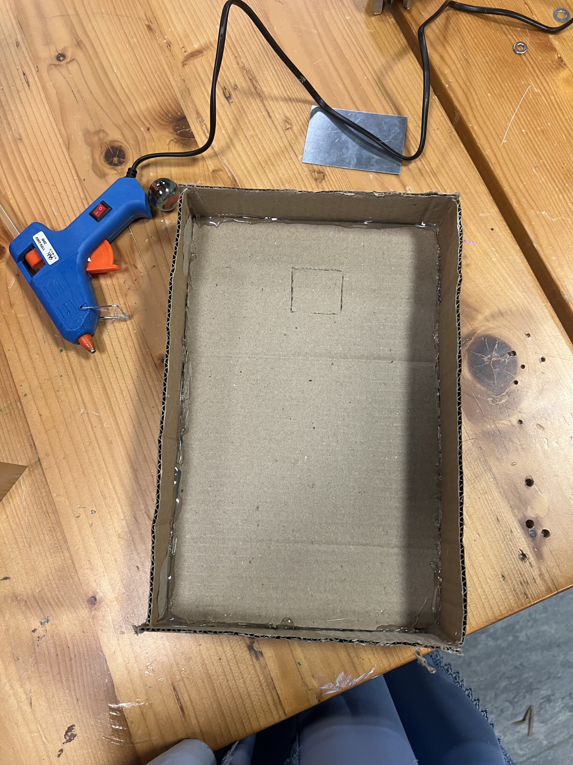
For this project, the goal was to create a creative switch using Arduino that could be activated with a body part other than the hand. At first, I wanted to make something you could blow on, kind of like a tiny football field made out of cardboard where you blow a ball to complete the circuit. But I quickly realized the ball I was using was too light, so it didn’t push the wires together properly.

After trying a few different ideas, I switched to a bigger marble. But since it was heavier, blowing on it didn’t work either. That’s when I got the idea to make it something more fun and active, something you kick instead of blow. It turned into more of a little game than just a switch, which made it a lot more exciting to work on.

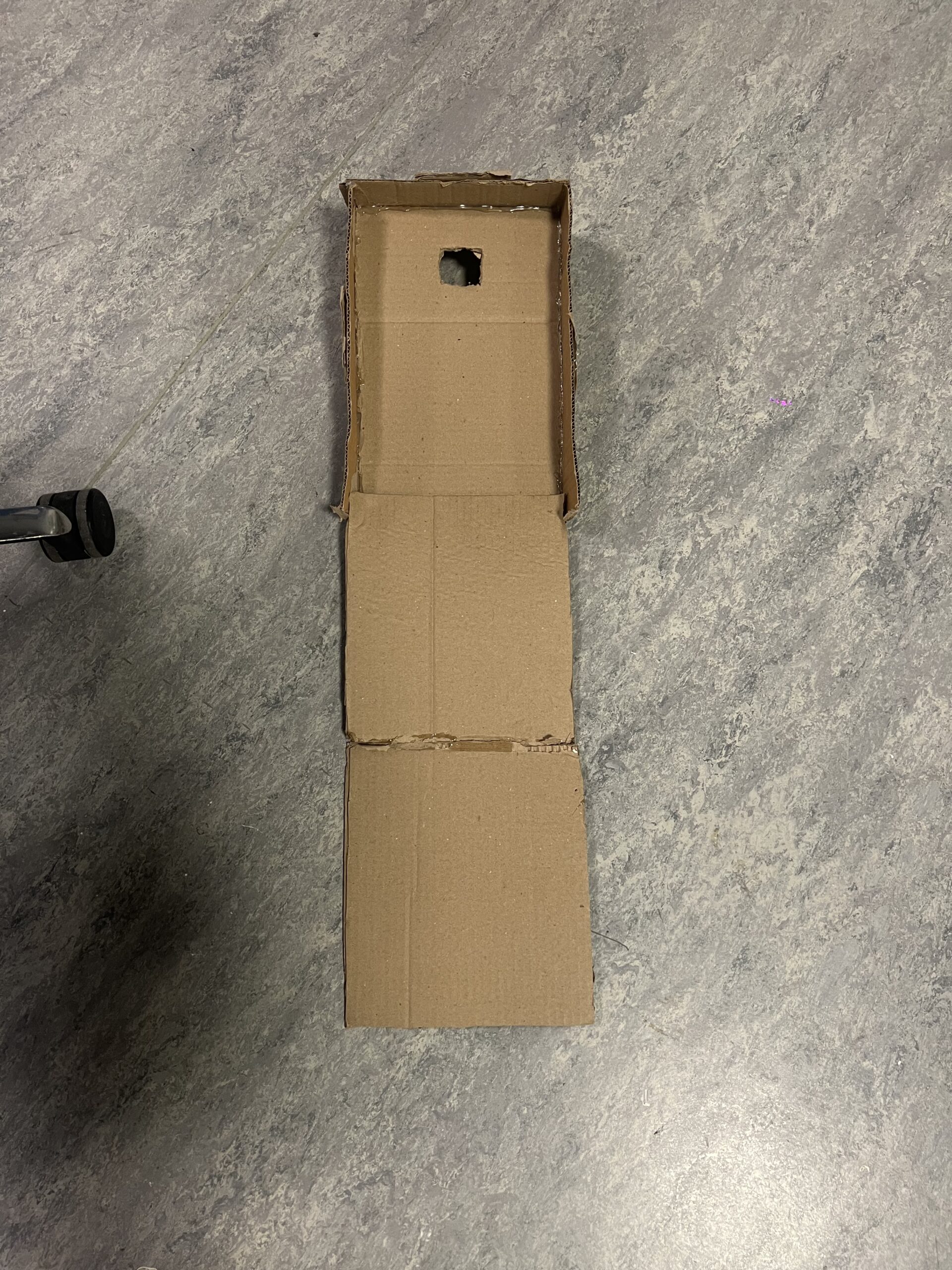
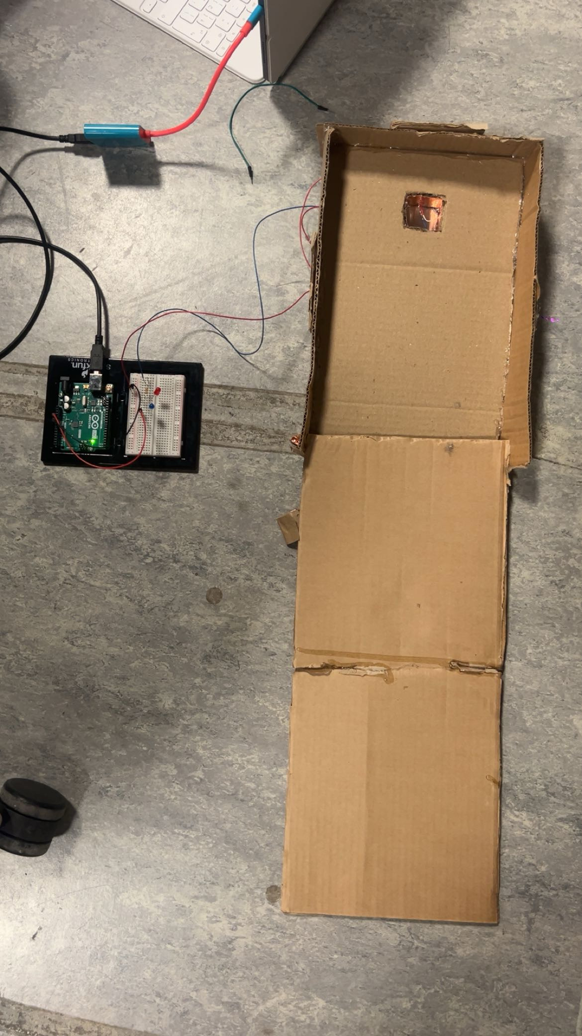
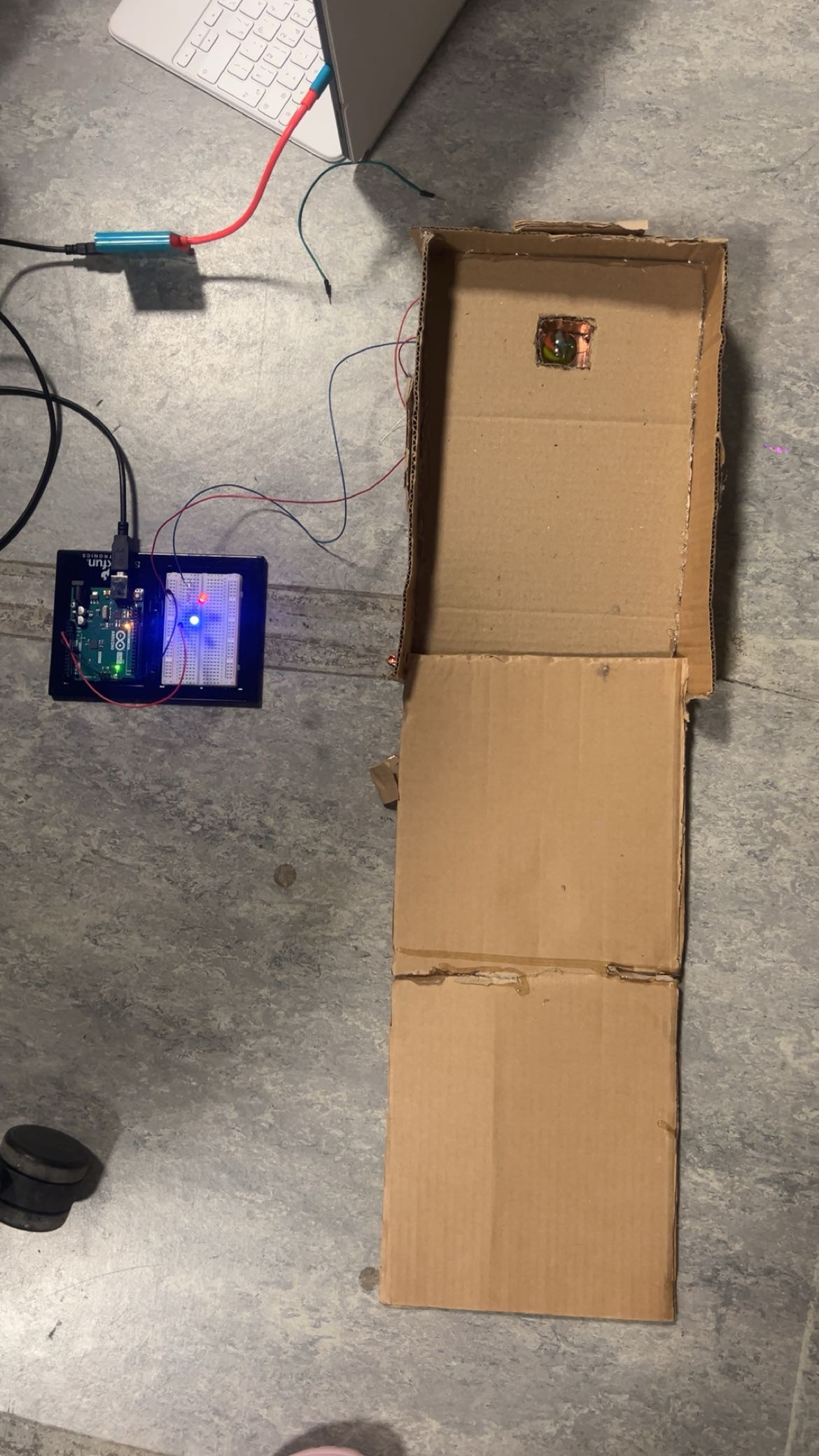
In the final version, the goal is to kick the ball into a hole. When the ball lands perfectly in the hole, it completes the circuit and makes the bulbs light up. If you miss, the lights stay off. I really liked this idea because it feels like a reward, the light turning on means you “won.” It doesn’t happen automatically; you have to earn it.

What I enjoyed most about this project is how it started as a simple idea and ended up becoming something playful and interactive. It reminded me that creativity often comes from solving problems, sometimes when something doesn’t work, it actually pushes you toward a better idea. I also liked how it connected movement and technology. Using my foot instead of my hand made it feel more like a real-world challenge or game.

Design

The design of my project is a cardboard slope that works kind of like a mini golf game. At the end of the slope, there’s a hole made out of cardboard that acts as the main target. I covered the inside of the hole with copper tape because it’s a good conductor of electricity. Underneath, I made two small holes where I inserted the wires. These wires touch each other only when the ball goes into the hole, completing the circuit and lighting up the bulb. I really like how simple but effective it is when you kick the ball just right, the light turns on as a little celebration of success.


weird switch

For my project, I was inspired from the gym leg adductor machine where you have to close your legs against weight to work on your inner thigh muscle. I created the circuit just like in class but I added the 2 strips of copper tape on my inner thigh so that they when the legs were closed, the electricity would flow through. I also added crocodile clips just to extend the length of the circuit.

IMG_2157

I drew a rough schematic on how I wanted the system to work.


Week 8: HeartFelt Connection

There is something profoundly magical about receiving affection: a hand that reaches out, a presence that wraps you in warmth, a small gesture that makes the world feel less heavy. Love, in its quietest form, has the power to make us feel seen, valued, and alive. Through my project, I wanted to explore that invisible current the emotional electricity that flows between two people who care for each other.

The interactive piece symbolizes the way love and connection illuminate us. When you touch the hand of someone you love, or even move close enough to feel their presence, your heart lights up  not just metaphorically, but literally within the work. The glowing heart represents how affection has the power to activate something deep within us, a light that reminds us we are not alone.

Demo Video:


Future Improvement:

If I had more time, I would have expanded the project to include sound and more expressive lighting to create a deeper emotional experience. I would have added soft heartbeats, ambient sounds, or even gentle whispers that respond to movement and proximity. As two people approach each other, the soundscape could evolve, symbolizing how connection changes both our inner feelings and the atmosphere around us.

I also would have made the heart light more dynamic by allowing it to change color and rhythm based on the kind of relationship or emotion being expressed. Warm tones could represent comfort and love, cooler shades could suggest distance or nostalgia, and rhythmic pulses could express moments of excitement and joy. These additions would transform the project into a poetic language of sound and light, a more immersive way to express how love and presence illuminate our lives.

Week 8 – Unusual Switch (Foot-Activated Circuit)

 Step-On Switch:  An Unusual Arduino Foot-Activated Circuit

Video:

Overview:

For my first Arduino assignment, I created an unusual switch that does not require the use of hands. My switch is activated by pressing it with the foot, completing the circuit to light up two LEDs (red and blue). The idea was to create a physical interface that feels natural, intuitive, and accessible, something that could fit into everyday gestures like stepping, rather than pressing buttons with fingers.

Inspiration:

I was inspired to use the feet after thinking about how often we interact with objects using our hands, keyboards, phones, remotes,  and how limiting that can be. I wanted to explore another part of the body to interact with technology in a more grounded and physical way.
The foot felt like an interesting choice because stepping on something has a clear and satisfying feedback, it’s an action that already feels like a switch. Plus, it connected to the idea of accessibility, making a device that could be triggered without hand movement.

Building Process

Since this was my first time ever using Arduino, I learned a lot through trial and error and by asking questions in the IM Lab. I gathered all the materials from the lab, mainly cardboard scraps, metal sheets, and wires.

Here’s how I built it:

  1. Base:
    I used a folded piece of scrap cardboard to create a “step pad.” The bottom layer held the metal conductor (two rectangular aluminum sheets), while the top layer acted as a flexible pressure surface.
  2. Wiring and Circuit:
    I made my own extended wires since the ones in the kit were too short. Professor Mang showed me how to cut and separate the wires together safely. I then taped the two wires onto the cardboard so that when the top layer was pressed, the exposed wire ends touched the metal conductor, closing the circuit and turning on the LEDs.
  3. Circuit Connection:
    The switch was connected to an Arduino Uno and a breadboard. I programmed it so that when the circuit closed (when someone stepped on it), both red and blue LEDs would light up.
  4. Interface Design:
    To make it more intuitive and visually clear, I designed a quick cover on Canva that said “STEP ON ME,” giving the switch a fun and inviting personality. It also made the prototype feel more like a finished (polished) interactive product.

Overall Reflection:

I really enjoyed how hands-on this project was, literally using my feet instead of my hands. It helped me see how electronics can interact with the body in playful, unexpected ways. I liked that the result felt tactile and responsive, and it gave a sense of satisfaction when the LEDs lit up under my foot.

What I could improve next time:

  • I would make the structure more durable using thicker cardboard or a sturdier base, since repeated stepping eventually weakened it.
  • I wish I had more time to maybe figure out how to add all four different colored LED lights to make it look more visually appealing
  • The wiring could be cleaner and more hidden, maybe integrated into the design itself for a more polished look.

Schematic:

This schematic illustrates how my foot-activated switch completes the circuit to power the red and blue LEDs. The 5V output from the Arduino flows through the LEDs and a 330Ω resistor to limit current. The circuit remains open until the metal conductor plates make contact, this happens when I press the cardboard switch with my foot. Once pressed, the metal pieces touch, closing the circuit and allowing current to flow, which lights up both LEDs. This simple setup demonstrates the bones of how my arduino circuit work and was the plan I followed to make building this project much easier.

Conclusion

This project taught me the basics of Arduino, digital input/output, and how creative thinking can shape how we interact with technology. Building a switch with my foot instead of my hand made me realize that interfaces don’t always need to follow convention, they can be playful, personal, and unexpected.

Week 8 – Shahram Chaudhry – The Pressure Within

I’ve always been fascinated by pressure sensors – the way a simple press or change in force can trigger something to happen. You see them everywhere: in home alarm systems, automatic doors, and even in those dramatic scenes from Mission Impossible, where a character steps on the wrong tile and sets off a trap. That kind of precision and sensitivity has always intrigued me. So, when I realized I could actually build one myself, I thought, why not?

The concept seemed simple enough at first: a pressure-activated switch that lights up an LED when you press on it. But I didn’t want to make something tiny that would trigger with a fingertip,  I wanted it to react only to real weight or force. My vision was to create a larger pressure pad, something that felt closer to those movie sensors that go off when someone steps on them. I figured, “How hard could it be?” Spoiler: harder than I thought.

In the beginning, I tried to build everything at once , the sensor pad made from cardboard and aluminum foil layers, and the circuit on the breadboard. The problem was, when it didn’t work, I had no idea why it wasn’t working. Was it a loose connection? Or had I messed up the circuit itself? I went back and forth for a while, trying to fix both at the same time, which honestly just made it more confusing.

To make things worse, I started out using thin copper wire, thinking it would be neat and professional-looking. But those wires didn’t hold contact well at all, every time I moved the board a little, the connection would break. After a few frustrating tries, I switched to jumper wires, which made testing much easier. Around that point, I decided to simplify the problem by building a smaller version first. I wanted to prove the circuit worked before investing time into rebuilding the big pressure pad again.

I realized the key was to finish and test the circuit first basically, to complete the LED and resistor setup with two extra test wires, make sure it lit up when the wires touched, and then integrate those wires into the foil pad. Once I took that approach, the small version worked flawlessly, and then the larger version came together perfectly afterward. 

​​I first used a green LED just to test the circuit, but later I wanted the project to feel more meaningful. I chose red instead not just because it looked like an alarm color, but because it represents the anxiety and tension that come with pressure. It’s a small change, but it gave the whole project a deeper meaning.

Here’s the video demonstration of both the small and large versions of my pressure sensor project.

IMG_0571 IMG_0580

Week 8: Unusual Switch

Concept

The idea behind this project is to create a hands-free switch that uses body weight to control a simple electrical circuit. When someone sits down, the pressure causes two layers of aluminum foil, separated by a bouncy piece of foam, to touch, completing the circuit and lighting up an LED. When the person stands up, the foam returns to its original shape, breaking the connection and turning the light off. This project demonstrates how everyday materials like foil and foam can be turned into a functional pressure-sensitive switch, showing how creative design and basic electronics can work together to make an interactive, responsive object.

Image & Video Documentation

Future Improvements

In future versions, the pressure switch could be made more durable and precise by replacing the foil with conductive fabric or copper tape, and using a softer, more uniform spacer material to ensure consistent contact. It could also be used to trigger more complex outputs, such as sounds, animations, or notifications, when someone sits down. Equally important, it could also be made more aesthetically pleasing by adding color and by making it smaller, making it not only functional but also a cute device to have hidden somewhere, such as on a chair.

Week 8 Production Traffic Light Pedal Keyboard

Concept

This project takes inspiration from the dual-manual organ, an instrument that engages both the hands and feet to create layered musical expression. Similarly, I wanted to explore how interaction not only through hands can become a creative control method. I built a pedal-activated LED system, allowing the user to light up different colors by stepping instead of using their hands. The choice of red, yellow, and green LEDs draws directly from the universal language of traffic lights, symbolizing stop, pause, and go, which could creates a visual rhythm that also parallels musical tempo. The pedal thus becomes both a practical switch and a metaphor for coordination and rhythm through movement.

Image & Video Documentations Video(Download)

Future Improvements

Building this project helped me better understand how simple sensors and physical actions can create meaningful interaction. The foot-controlled design felt intuitive and playful, emphasizing how movement can extend beyond the hands in creative electronics. However, I also noticed that the current version only allows a binary on-off behavior. In the future, I’d like to make it more expressive, for example, by integrating pressure sensors so that the brightness or color changes based on how hard the pedal is pressed, or adding a fade-in/out animation for a smoother, more musical response. Another possible direction is to connect the pedal to sound or musical output, letting each color correspond to a tone similar to the dual-keyboard organ.

Week 8: Unusual Switch

Concept

The creation of an unusual switch was an interesting task, considering I have created simple LED circuits before, though never with anything beyond what is given in our kit. I decided to use a piano key as a switch to create an interesting switch to add an element of sound that adds dimension to the switch and work. Through this I wanted to create an engaging yet simple work that helps me ground my understanding. To add another layer I wrote code for the light to blink when the key is pressed, which adds a visual to the current auditory element.

Video Demonstration

IMG_7568

Code Snippet

void loop() {
  //Read the state of the switch
  int switchState = digitalRead(A2);

  //Loop to blink if switch is ON
  if (switchState == HIGH) { 
    digitalWrite(13, HIGH); //Turn the LED ON
    delay(250);  // Wait 250 ms
    digitalWrite(13, LOW);   //Turn the LED OFF
    delay(250);  // Wait 250 ms         
  } else {
    digitalWrite(13, LOW); //Keep the LED OFF
  }

}

During this assignment I wanted to integrate two different things we learnt in class to add a little more interactivity to the switch so I decided to use the blinking mechanism during the time where the switch is connected. After prototyping with the regular switch, I added the part of the code where the blinking is handled and noticed a difference on how engaging the switch became which could be useful in creating game interactions or bringing a viewer’s attention to a specific part of a work of interactive art.

Complete Code

Github link

Reflection

This assignment was a great starting point for learning arduino, though a simple task, it helped me make sure that I am well acquainted with the basics of it and I am now excited to learn more. I’d say there is a lot that could be done to improve and develop this work, including adding more LEDs, switches or even more complex visual display when the switch is turned on through a more complex use of digitalRead. Further, this taught me the potential of both hardware and software interacting and what type of work could come out of using such tools together, which inspired me and got me thinking about future projects and how I could make use of this dynamic or how I could have used it in my previous projects.

Reading Response

Attractive Things Work Better

It was really interesting for me to learn how human cognition and emotion are intertwined and how that relationship can determine which design is the best. I personally agree with the author’s idea that more aesthetic and pleasing designs can enhance people’s creativity and allow them to accept even small mistakes or glitches. However, I think that even if a design is aesthetic, if it is too complicated and difficult to use, it will still make me feel frustrated. 

Thus, I believe it’s all about finding the perfect balance between usability, aesthetics, and the emotional impact we gain from the design. In terms of the emotional impact, it is very hard to determine which design works best for people in both pleasant and stressful situations. However, I think it’s always important to make designs both aesthetic and simple at the same time. For instance, Notion is a very simple yet visually pleasing website, and I think that was the key to its success. I know where the templates are, so I can easily choose which template I want to use for my daily diaries and so on. As a software engineer, it is always hard for me to find the right balance between simplicity and aesthetics. However, getting as much user feedback as possible makes it easier for me to find any improvements and add features that make people’s lives easier.


Her Code Got Humans On The Moon

As someone who wants to become a software engineer after graduation, I totally agree that the way Hamilton approached designing software that handles crucial tasks and resolves real-time errors is very important, especially in today’s society. Nowadays, anyone can build almost anything from scratch due to technological advancements without actually knowing how to code at all. However, the real challenge that we, as software engineers, need to tackle is handling critical errors when something goes wrong. If we do not understand the fundamental principles of how software interacts with other components, such as databases, everything in this world will start to malfunction. 

After reading this article, I realized that I want to become a software engineer like Hamilton who can prioritize customers’ needs in  the first place and handle errors in real time. I believe these two skills are fundamental parts of a software engineer’s job in today’s world.

Week 8 – Unusual Switch

Concept

I’ve been thinking a lot about how we usually interact with electronics. It’s almost always with our hands; pressing buttons, turning knobs, typing. So I’m glad we got to try something different. My idea for this project is to have a foot-activated Arduino switch made with nothing more than aluminum foil, tape, socks, and (curiosity).

The idea is simple. When your feet touch, they complete a circuit, and when they move apart, the circuit opens again. Your body becomes the bridge that carries a tiny signal. I wrapped strips of foil around my feet (over socks), taped them so they wouldn’t slip, and connected one to pin 2 on the Arduino and the other to ground. When the two foils touch, the Arduino reads a HIGH signal, meaning the circuit is complete.

Demonstration

IMG_5452

Code

int footSwitchPin = 2;   
int ledPin = 13;         

void setup() {
  pinMode(footSwitchPin, INPUT);
  pinMode(ledPin, OUTPUT);
}

void loop() {
  int footState = digitalRead(footSwitchPin);  //check if feet are touching

  if (footState == HIGH) {
    digitalWrite(ledPin, HIGH);   //feet together = LED ON
  } else {
    digitalWrite(ledPin, LOW);    //feet apart = LED OFF
  }
}

Challenges and Improvements 

The biggest challenge was stability. The foil sometimes slipped or wrinkled, breaking contact even when my feet were touching. The tape would loosen after a few tries, so I had to adjust it constantly.  On the creative side, it would be fun to connect it to a sound or visual program on a computer. For example, every time your feet meet, a sound plays or a color changes on screen. That could turn this tiny experiment into a music or art performance piece.