
For this week’s assignment, I made a switch with the help of a hole puncher. The main idea is to use the metal cutting poles that cut the paper after you press the hole puncher. Here’s a link about how a hole puncher works in slow motion.
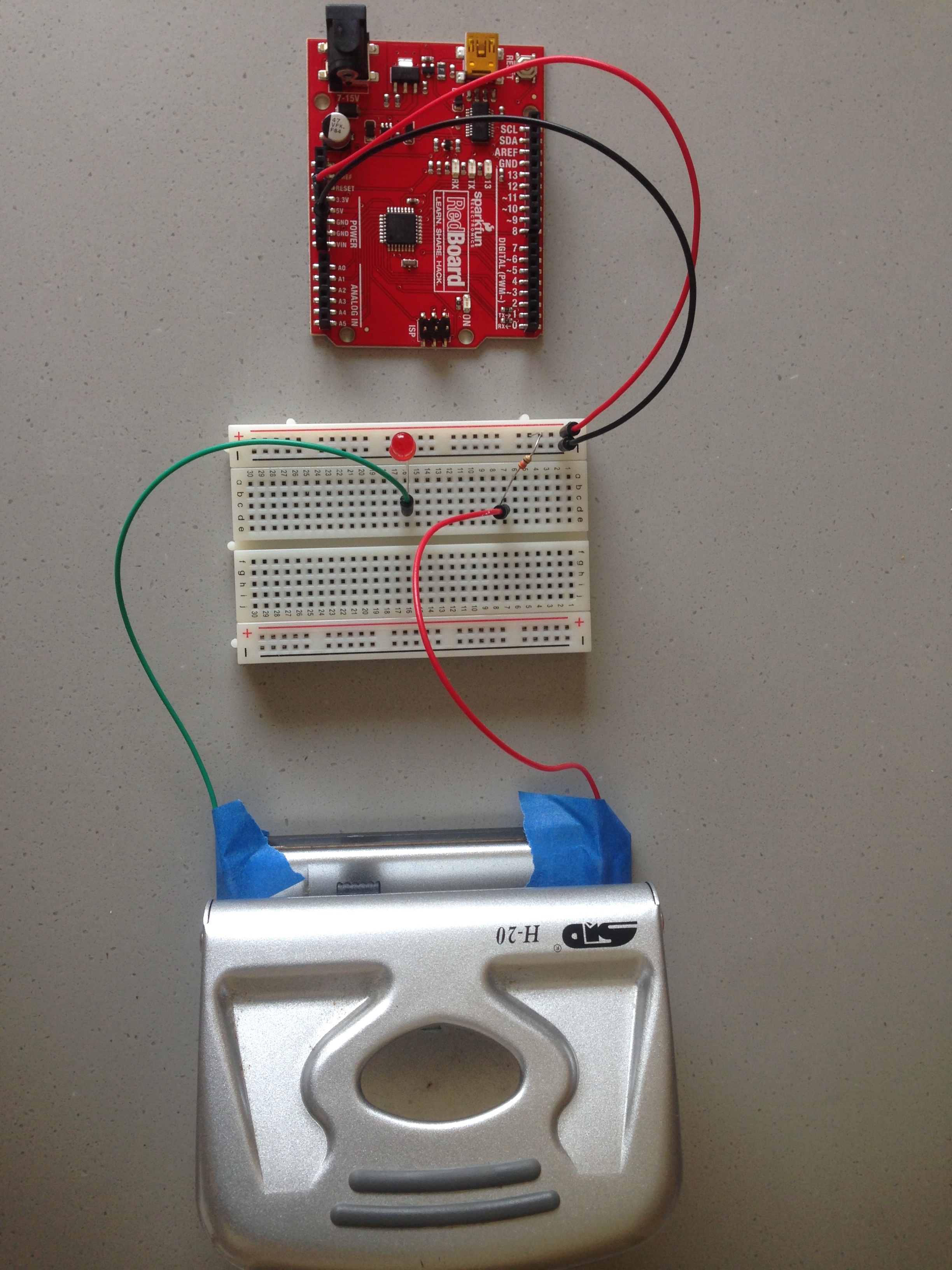
For my project, I first connect the breadboard to power and ground using a red and a black wire. Then on the breadboard, I put a 330 ohms resistor and a red LED light in series. In the circuit, the hole puncher is put between the resistor and the LED light. A red wire connects the resistor and the hole puncher, and a green wire connects the hole puncher and the LED light. The pins of the green and red wires are taped on the hole puncher. The position where the pins are taped allows the pins to connect to the cutting poles after you press the hole puncher. Once the pins are in direct contact with the metal poles, the circuit becomes a closed circuit and the current will light up the LED light.
Of course, to fulfil the requirement of the assignment, I need to switch the light on without my hand. Thanks to the big hole puncher that I can switch on the light using my foot. An illustration video is attached below. Hope you enjoy it!