For my final project, I decided to upgrade the balloon game I developed for the midterm project. For the game itself, I want to have different colors that pop at different rates so this could be used as an analysis test for risk-taking abilities. To make it physically interactive, I will be adding sensors that detect blowing from the user in real life. One way I would do this is by making something spin as the user is blowing and then a motion sensor to detect the spinning (something like a fan). I can imagine this to be challenging, so plan B would be using a potentiometer or a button to inflate the balloon.
After inflating it, the user could “collect” the balloon of that round by pressing a button or a brake pedal and another round is displayed until the game ends. The piezo buzzer will be used for the popping sound of the balloon. The score will be displayed in a screen (LCD or neopixel).
I will also be developing the result to make it more specific than just a score; it would calculate the number of pumps based on the color and give specific personalized result on their learning abilities.
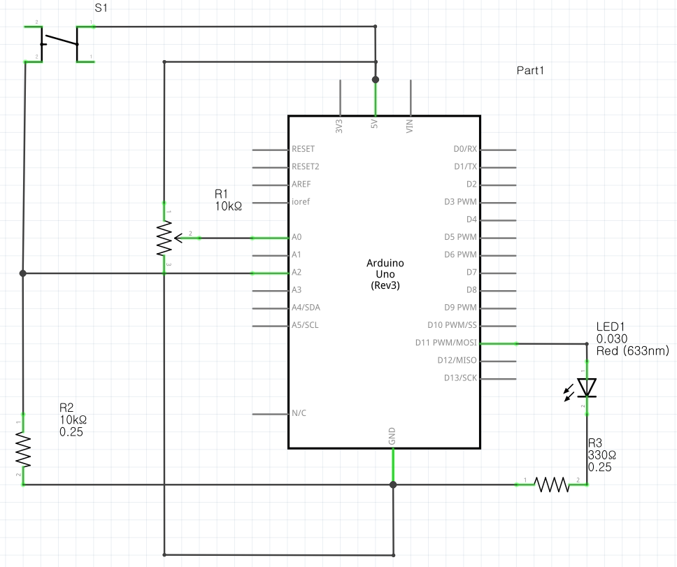
Schematic: It includes all 3 exercises using 1 Arduino.
Exercise 1
Arduino Code:
void setup() {
  Serial.begin(9600); // initialize serial communications
}

void loop() {
  // read the input pin:
  int potentiometer = analogRead(A0);
  // remap the pot value to fit in 1 byte:
  int mappedPot = map(potentiometer, 0, 1023, 0, 255);
  // print it out the serial port:
  Serial.write(mappedPot);
  //Serial.println(mappedPot);
  // slight delay to stabilize the ADC:
  delay(1);
}
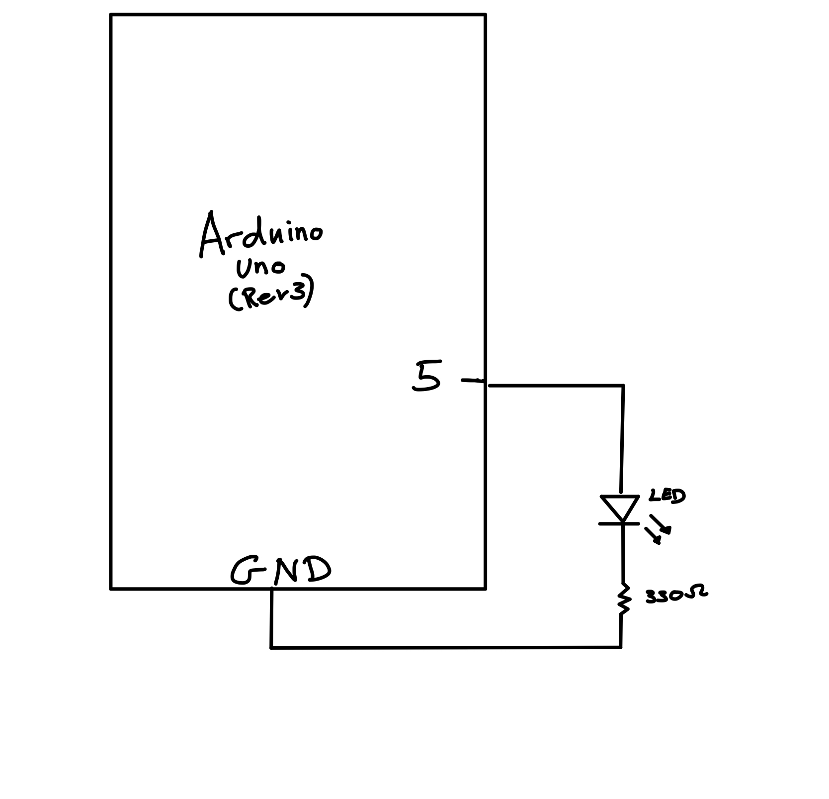
Exercise 2 (cred to Aisha)
Arduino Code:
int LED = 11;

void setup() {
  Serial.begin(9600);
  pinMode(LED, OUTPUT);
  // start the handshake
  while (Serial.available() <= 0) {
    Serial.println("Wait");  // send a starting message
    delay(300);               // wait 1/3 second
  }
}

void loop() {
  // wait for data from p5 before doing something
  while (Serial.available()) {
    int brightness = Serial.parseInt();
    if (Serial.read() == '\n') {
      analogWrite(LED, brightness); // turn on LED and adjusts brightness
      Serial.println("LIT");
    }
  }
}
For the final project, I would like to improve on the pac-man game that I developed on p5.js for my midterm project. I was a bit confused about whether to start a new project from scratch or build up on my midterm project. However, I realized that my goal for this final project is to focus more on hardware and physical computing stuff. This is because I am not experienced in this area at all and would like to have the final project as an opportunity to challenge myself and try out designing creative things with Arduino.
While doing my midterm project I faced some minor issues with the code for the game. Therefore, before creating an interaction between p5.js and arduino, I would like to fix these issues in the game by using for example the colors of the pixels to determine when the pacman hits one of the walls instead of using many if statements.
Using hardware devices to Control the Game
After fixing these issues I would like to use different devices that we learned about in the class to control the game and make it more interactive with the user. For example, I can use four buttons to control the motion of pacman. One button that moves pacman up, another button that moves pacman down, another button that moves pacman to the left and another one to move pacman to the right.
Furthermore, I would like to use the LCD screen to display the score in the game. However, this might be a challenging task as the LCD screen needs 12 wires to be soldered which will be difficult for me because I never did soldering.
In addition to this, I might use the potentiometer to change the difficult of the game by increasing the speed of the ghosts as this would make the game more interesting. Finally I would like to use the piezo buzzer to give different sound effects throughout the game. For instance, if you lose the game the piezo buzzer will be giving a losing sound effect.
Make something that uses only one sensor on arduino and makes the ellipse in p5 move on the horizontal axis, in the middle of the screen, and nothing on arduino is controlled by p5:
Exercise 2:
Make something that controls the LED brightness from p5:
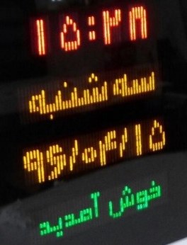
The premise of my project is very simple: construct and display Persian/Arabic letters on Arduino LCD, with the main purpose of displaying the Persian calendar date (Hijri Shamsi) – as a gift to my dad (an older generation electrical engineer). But you can input anything through p5.js to be displayed on the LCD.
Note: Hijri Shamsi is an ancient solar calendar and one of the oldest in the world. It begins on the March equinox as determined by astronomical calculation to mark the beginning of spring, where we celebrate new beginnings (Nowruz). The months’ names are the same as ancient Zoroastrian names (represented with Farsi letters, read right to left). The days are represented using Hindu-Arabic numerals.
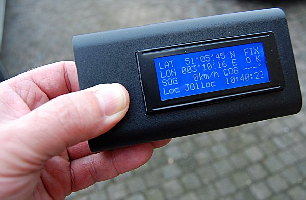
Sample digital representation of Hijri Shamsi dateSample box to hold the LCD
Like all sophisticated projects, however, the devil is in the details.
Displaying special characters on LCD:
lcd.print() function only supports ASCII characters. A series of calculations and mappings are involved in order to display special characters.
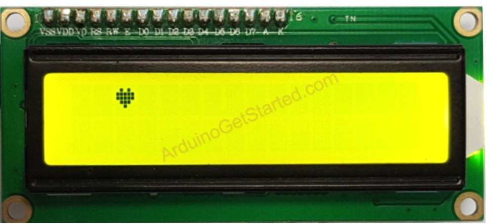
LCD 16x2 can display 32 characters (2 rows, 16 columns). And each character is composed of 40 pixels (8 rows and 5 columns). You will have to write your own bit-level custom character code. Take a look at the example below:
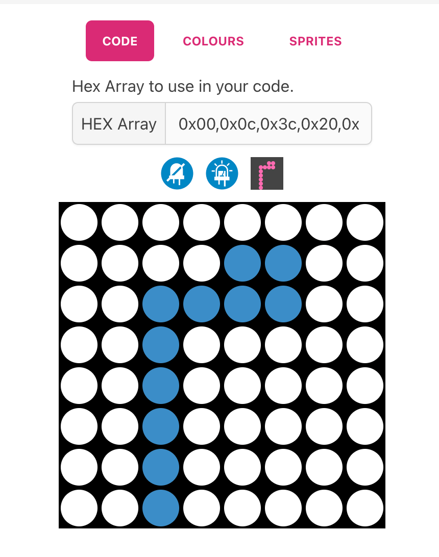
The good news is that you can make your own letters or special characters (and fonts) on a matrix on this website and get the HEX representation for your letters.
hex representation of letter م
This is the Persian alphabet matrix (credits to gurgleapps) that I will use in this project:
And the final step is presenting the character on the LCD. If you look at the heart example above, you see a bit-level representation of the character, but gurgleapps gives us a set of hex values. So some conversion needs to happen here. Each hexadecimal digit represents four bits (binary digits). We could write a simple but useful function that converts each hex value to bitmap characters and [depending on cursor position] display the custom bitmap.
p5.js:
p5.js is where the user input is stored and communicated to Arduino over serial operations. P5.js would take the input in English, convert it into Farsi, and send it to Arduino to display on LCD. The user has to let the program know, after inputting the text, whether they want the program to translate or transliterate the text to Farsi.
Note:
This is ambitious; if the translation part does not fit into the timeframe, p5.js will only convert computer date to Shamsi date, transliterate it, and display on the LCD.
Challenges:
The biggest challenge is perhaps constructing words (my name consists of letters م ر ی م. But almost all letters have a compact form that you have to use when writing words, so my name reads مریم ). This explains why I have several variations of one letter in the hex matrix. The way I would approach this is through many rounds of trial and error and experimenting with spacing and character sizes.
The next challenge would be displaying each character in a reverse manner (the letters read from right to left). The cursor has to be reversed every time there is a character input.
The 16×2 screen is limited and there will be character overflow and boundary issues, but the main goal here is to display the date and the LCD offers more than enough space for that purpose.
Timeline:
The week of November 28th: Experiment with displaying standalone letters. Get a good idea of the 16×2 space and the position of the cursor.
The week of December 5th: Get input from p5.js. Ensure the characters form words in a correct and consistent manner.
The week of December 12th: Experiment with adding colors. Build a frame for the LCD (a small structure with a stand so it could be put on disk). Prepare for the showcase.
children’s interactive bookchildren’s interactive book
For the final project I wanted to create an interactive recipe book. I was in
spired by the interactive children’s books, where the child could move or
pull parts of the book to interact with the story. I would use Arduino to allow the user to interact with the story/recipe on the computer screen.
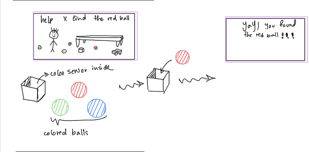
I started to brainstorm ways the user could interact with a story/recipe. (at this point I was just trying to find what sensors could be used and the possible ways, I didn’t know what the story would be or the scenes/interactions that I needed)
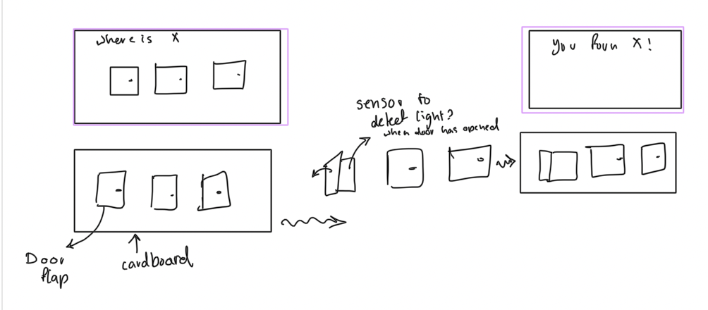
I then started to brainstorm ideas and decided that an interactive children’s cook book would be interesting. I think I would only create the interaction for one recipe (because of the limited time) but I hope to keep the idea of possible expansion when building the hardware to make sure that it is expandable.
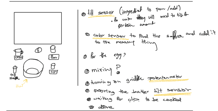
I found some recipes that I liked and listed some of the main steps then tried to find sensors that could be used for the interaction.
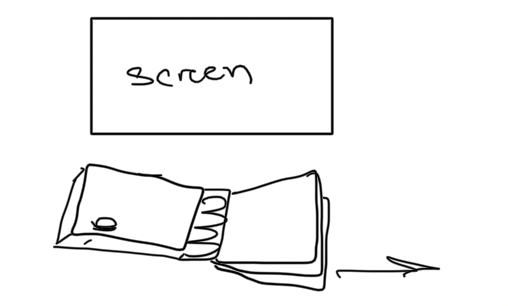
I then started to think of the structure that would hold the Arduino parts. had two ideas for this project. I could either create a wooden structure(explained later) or a book like structure. I would use cardboard as the pages and would stick the buttons and so on between pieces of cardboard to make sure that the wires are hidden. There a few things I would need to resolve when it comes to this idea. for example I would need a lot of sensors and buttons (… etc) because each page has it’s own. I would also need to decide how I’ll store the microcontroller and where the wires would go. Another issue is scalability. To use the device to tell another store/ show another recipe I would need to create another book.
pages in book
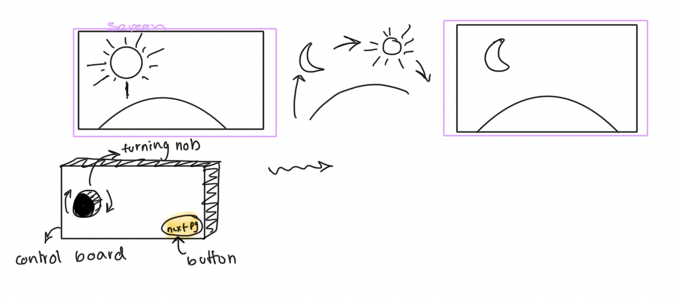
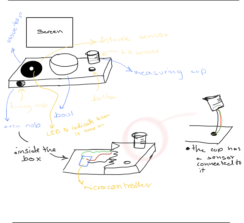
the second idea is to create a wooden structure that would hold the Arduino Uno microcontroller (I also plan to use a shell instead of a breadboard to connect all the things to the microcontroller).
I would use black acrylic for the stove (I might add a red LED in the middle that turns on when the oven is turned on).
I will also have a potentiometer on the front left side that would act as the stove knob.
I would have a bowl glued to the middle of the board. There would also be a measuring cup on the board too.
The measuring cup would not be glued to the board because the user should be able to remove it and “pour” things into the bowl.
I might add an elastic string that connects the cup to the board so that it pulls the cup and wires back into place so the user doesn’t need to deal with putting the wires.
I might also use heater tubing around the title sensor’s wires so that they are not all over the place
I haven’t included this in the sketch below but I also want to include a cup that the user can scope ingredients from. I would glue it to the board with a distance sensor to detect the user’s hands are above the cup.
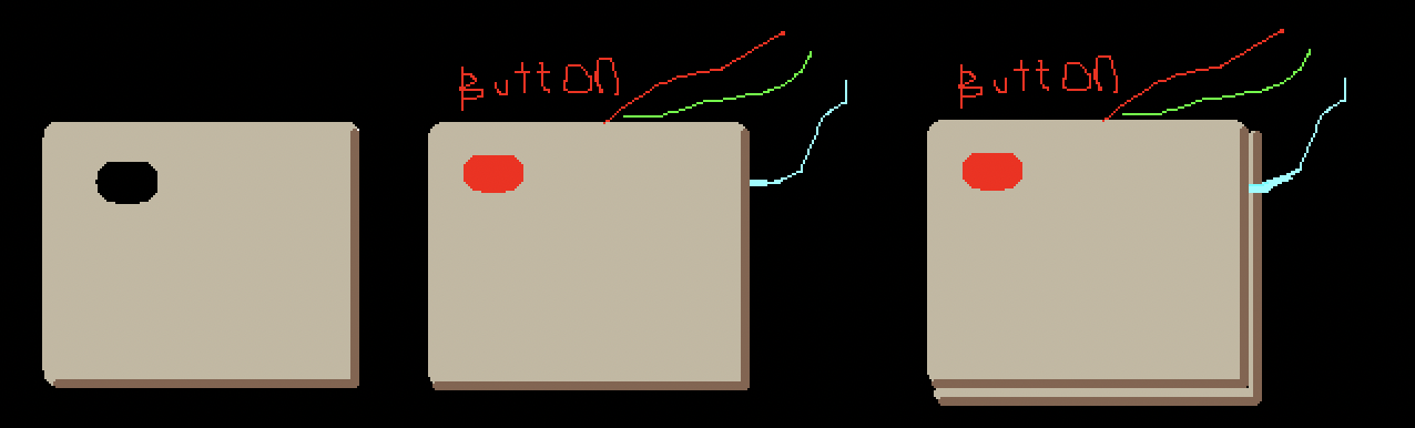
I would also add a button that would mainly be used to logistic reasons like moving to the next step or starting (haven’t decided the exact function yet)
There are still quite a few things to resolve but this is the current general idea. I plan to start the Arduino parts then build the structure to make sure I can fit all the things I want to include.
The schematic is made to be compatible throughout the assignment.
This schematic is used for Exercise 2.
Exercise 1:
make something that uses only one sensor on arduino and makes the ellipse in p5 move on the horizontal axis, in the middle of the screen, and nothing on arduino is controlled by p5
Arduino Code (Credit: Hessa):
void setup() {
  Serial.begin(9600); // initialize serial communications
}

void loop() {
  // read the input pin:
  int potentiometer = analogRead(A0);
  // remap the pot value to fit in 1 byte:
  int mappedPot = map(potentiometer, 0, 1023, 0, 255);
  // print it out the serial port:
  Serial.write(mappedPot);
  //Serial.println(mappedPot);
  // slight delay to stabilize the ADC:
  delay(1);
}
Exercise 2:
make something that controls the LED brightness from p5
Arduino Code (Credit: Aisha):
int LED = 5;

void setup() {
  Serial.begin(9600);
  pinMode(LED, OUTPUT);
  // start the handshake
  while (Serial.available() <= 0) {
    Serial.println("Wait");  // send a starting message
    delay(300);               // wait 1/3 second
  }
}

void loop() {
  // wait for data from p5 before doing something
  while (Serial.available()) {
    int brightness = Serial.parseInt();
    if (Serial.read() == '\n') {
      analogWrite(LED, brightness); // turn on LED and adjusts brightness
      Serial.println("LIT");
    }
  }
}
While brainstorming, I was trying to recall what interactive projects I’ve interacted with and enjoyed. I feel like key components that draw me personally to a project are the outcome, music, and how the body is used in the project.
My preliminary idea for the final project is to take the classic 2000s mobile game, Fruit Ninja, and make it live. If you’re not familiar with Fruit Ninja, it’s a timed game where the player has to slice as many fruits as they can using their finger(s). There are combos, bombs, and special fruits in the game, but to keep it relatively simple for implementation I will probably just have the player be able to slice one fruit at a time.
The physical component will be instead of the player using just their finger, they will use their whole body. For instance when they see a fruit coming, they will have to slice it using their arms. This might use the distance sensor. Another possible idea is to have multiple buttons, one representing each fruit, scattered around so the player will have to move to get the button.
I’m not sure if I will stick to this idea, but for now live Fruit Ninja will be what I’m going for.
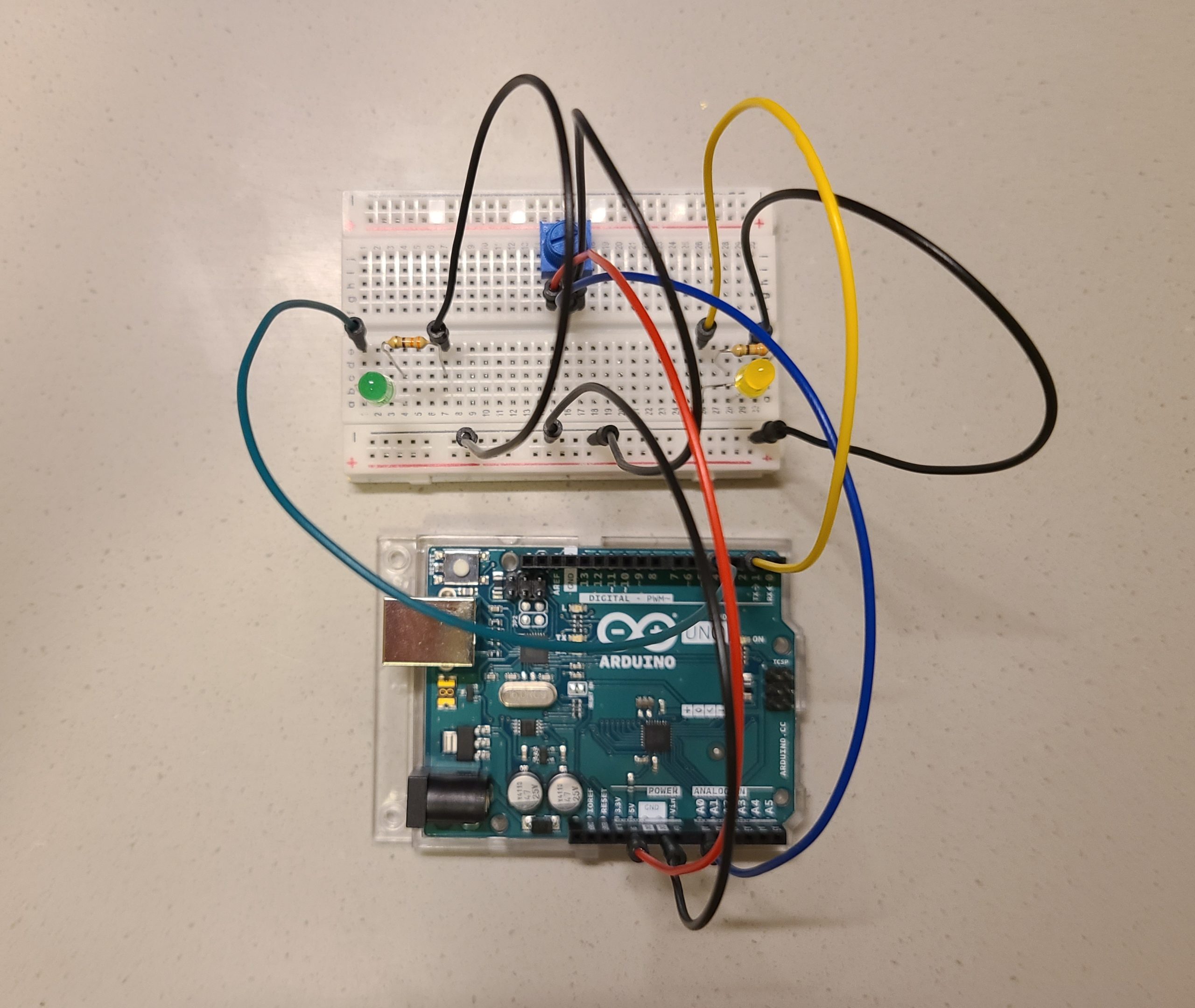
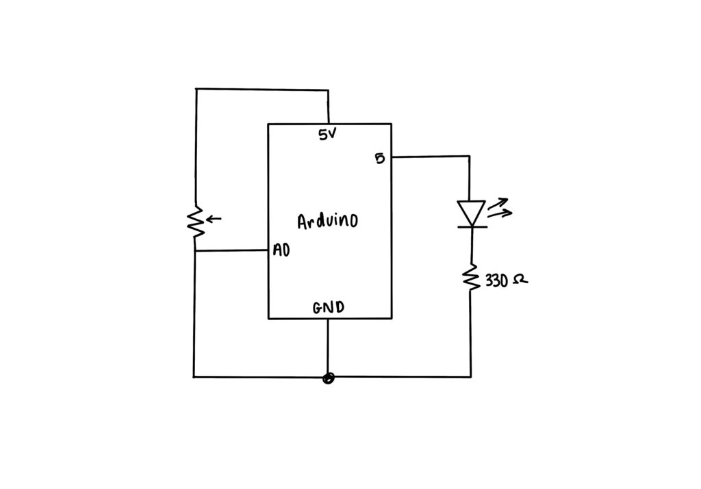
Here is the actual physical circuit and schematic we used for all three exercises. The actual physical circuit has two LEDs, one at pin 2, but it wasn’t illustrated because it wasn’t used, it was just there for testing purposes.
Physical circuit
Schematic (another LED at pin 2)
Exercise 1: Ellipse
Here is the link to the full code. It uses professor Sherwood’s example “Webserial Handshake” code, except it includes this line:
which maps the rVal to the x-position of the ellipse. Since the rVal reads from the Arduino, the ellipse x-position also changes as the sensor is being used. We used a potentiometer to control this.
Exercise 2: LED Brightness
Here is the link to the full code. At first we tried using up and down arrow keys, but we changed it to mouse click and then the mouseX position. So, for this exercise, we controlled the brightness of the LED using the mouseX position, where we mapped it to the values for the LED:
LEDBrightness = map(mouseX, 0, width, 0, 255);
We wanted it to be changing constantly, like how a potentiometer changes the LED constantly, but it didn’t work out that way. We tried printing the values and it turns out that the mouseX value is sent to the Arduino only once, so it doesn’t always get sent. However, when printing the LEDBrightness, it is constantly being checked.
Additionally, another version we tried was using the left and right halves of the canvas to change the brightness by using mouse input. The left side would make the LED dimmer, whereas the right side was the full brightness. This was used as a way of simplifying the program. The issue we ran into with this method was that the LED would be full brightness when clicking the right half, but when clicking the left half it would barely light up, even when the value for left was the same as the right value.
Exercise 3: Gravity Wind with Potentiometer and LED
Here is the link to the code. The code for this exercise uses Professor Mang’s example and the gravity wind example from Professor Sherwood with a few modifications. Firstly, there are boundaries set so the ball does not go out of the canvas. This is the code that checks if the ball bounces and then the LED will light up:
if (position_.y > height - mass/2 - mass) {
    if (velocity.y > 1) {
      serial.write(255);
    }
  }
It checks if the position of the ball hits the bottom edge of the canvas. It also checks if the ball is still bouncing based on the velocity.
And this is the code from the Arduino side for the LED:
Since we just used serial.write() in p5, when we Serial.read() it takes the value in the serial write (which is 255) and we use that to write to the LED.
As for the potentiometer that controls the wind, here is the code for it in p5:
So for our project, we wanted to do something artistic. The idea we have comes from the following piece of computer graphic art: Interactive Walls. The artwork is graphic and based on the software Max, but we thought it would look great if implemented with servo motors and multicolored panels in real life. The panels will be mounted to servo motors and be multicolored to look aesthetically pleasing. The panels can be made out of acrylic material or something lighter like thin plywood or cardboard. Due to restrictions of the Arduino Uno, we will only be able to use a maximum of 12 panels for our interactive artwork.
Concept visualization and further explanation can be found in Ahmed’s post
Functionality
We want the panels to depict a living, breathing, organism that reacts to different inputs; touch, noise, and input controls on a mounted panel. The artwork will have two speakers that will create a surround sound effect and output predetermined responses to different stimuli. The control panel for the artwork will have a few buttons that will change modes. Modes can be an ambient mode that makes predetermined patterns, music mode which will make the artwork react to music playing, and a touch mode that will allow the audience to touch the artwork and have it react to their inputs.
Additional Information
We also found the following code that may help us during the production of this project: Audio Reactive Program