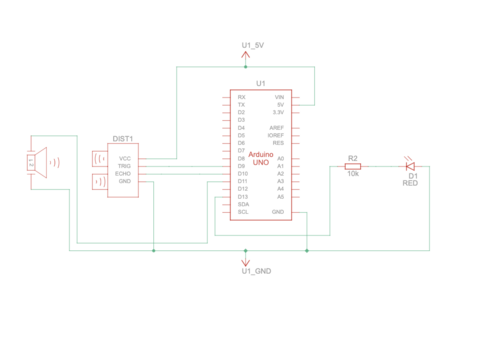
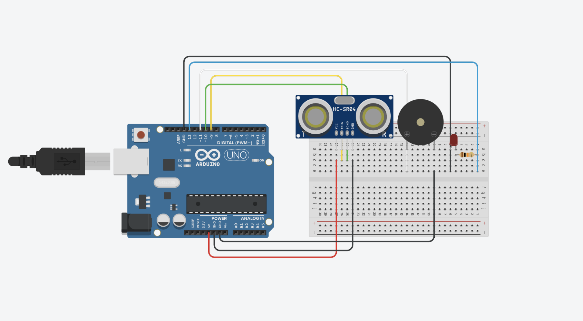
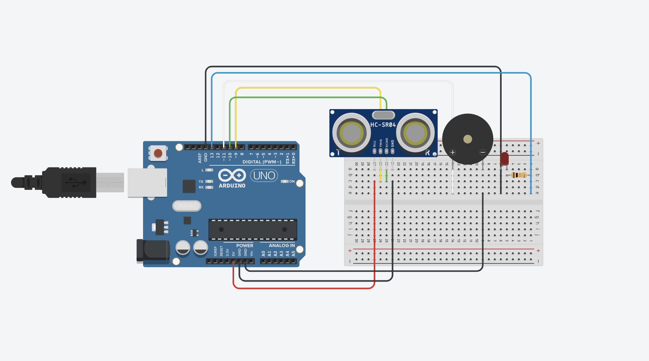
All Posts

Week 10: Musical Instrument – Keya and Mirette

Concept:

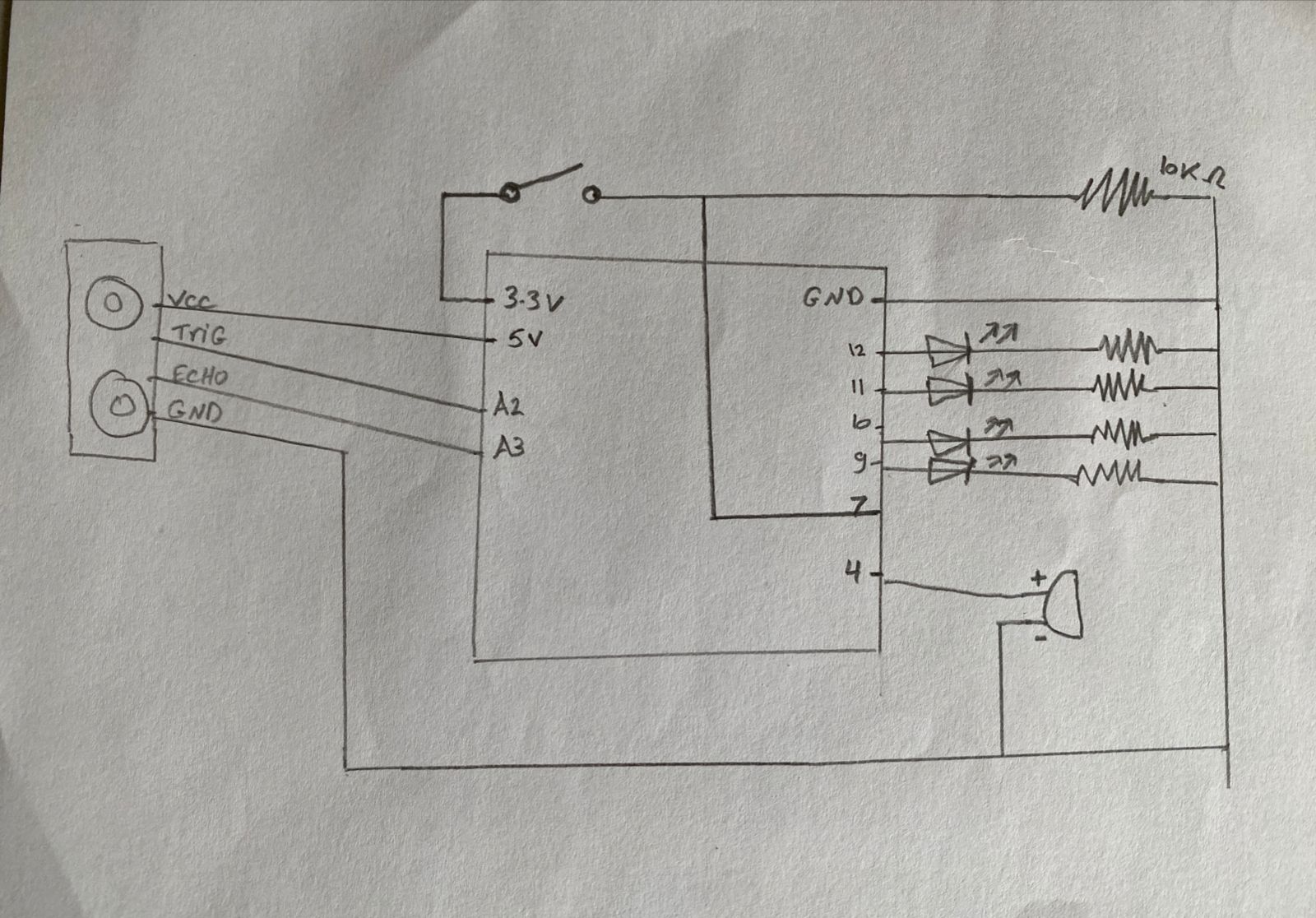
Our musical is sort of a 3 note piano with 3 octaves. There are three buttons that each play a specific note (A, B and C), and an ultrasonic sensor to measure the distance which in turn specifies the octave the user wants to play the notes in (3,4,5). The nearest interval plays the notes in the third octave, the next plays the notes in the fourth interval which sounds higher than the first interval and the last interval plays the notes in the fifth interval which sound higher than the middle interval. The buttons are controlled by switches that act as our main digital input and trigger specific notes depending on the secondary input which is the analog input from the ultrasonic sensor that specifies the octave to play the notes. We have also included an LED light that blinks when the instrument is first started and when the user has exceeded the range of the input from the ultrasonic sensor.  We included the pitches.h header file that was used in the example shown in class to get the notes played.

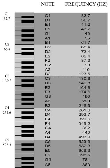
Notes played: A3, A4, A5, B3, B4, B5, C3, C4, C5.

Process & Highlights:

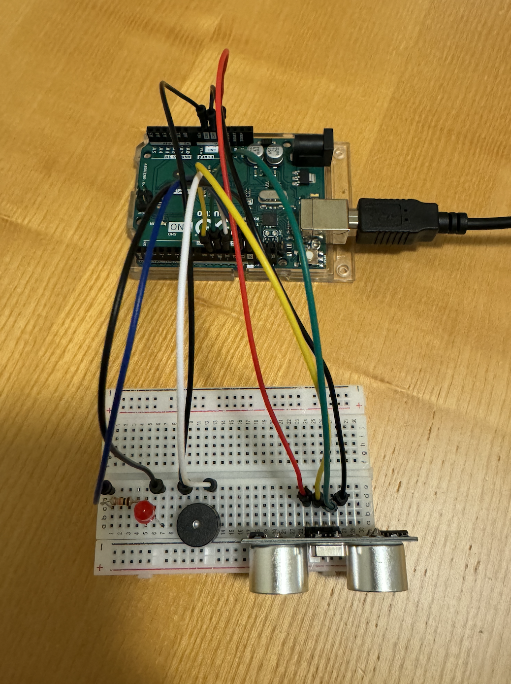
It was an interesting process trying to figure out how to connect everything together the right way and to get the ultrasonic sensor to work as expected, but once we figured everything out it was pretty easy to follow through the code. It helped to work as a team because we brainstormed the idea together and worked on the logic of the code and implemented it together which was more fun than working individually. I would say the highlight was finally getting it to work the way we wanted it to. 

Here is a video demo of our instrument:

Code:

const int trigPin = 9;
const int echoPin = 10;
const int ledPin = 13;
const int buzzerPin = 8;
const int switchPin1 = 2; // Pin for the first switch
const int switchPin2 = 3; // Pin for the second switch
const int switchPin3 = 4; // Pin for the third switch

float duration, distance;

// Melodies
#include "pitches.h"

int melody11 = NOTE_C3;
int melody12 = NOTE_C4;
int melody13 = NOTE_C5;
int melody21 = NOTE_A3;
int melody22 = NOTE_A4;
int melody23 = NOTE_A5;
int melody31 = NOTE_B3;
int melody32 = NOTE_B4;
int melody33 = NOTE_B5;


void playNote(int melody){
  tone(buzzerPin, melody, 800);
  delay(1000);
}

void setup() {
  pinMode(trigPin, OUTPUT);
  pinMode(echoPin, INPUT);
  pinMode(ledPin, OUTPUT);
  pinMode(buzzerPin, OUTPUT);
  pinMode(switchPin1, INPUT_PULLUP);
  pinMode(switchPin2, INPUT_PULLUP);
  pinMode(switchPin3, INPUT_PULLUP);
  Serial.begin(9600);
}

void loop() {
  digitalWrite(trigPin, LOW);
  delayMicroseconds(2);
  digitalWrite(trigPin, HIGH);
  delayMicroseconds(10);
  digitalWrite(trigPin, LOW);

  duration = pulseIn(echoPin, HIGH);
  distance = (duration * 0.0343) / 2;


  if (distance < 10) {
    Serial.println("Distance: 1");
    digitalWrite(ledPin, HIGH);   // Turn on the LED

    if (digitalRead(switchPin1) == LOW) {
      playNote(melody11); 
    } else if (digitalRead(switchPin2) == LOW) {
      playNote(melody21); 
    } else if (digitalRead(switchPin3) == LOW) {
      playNote(melody31); 
    }

  } else if (distance < 20) {
    Serial.println("Distance: 2");
    digitalWrite(ledPin, HIGH);   // Turn on the LED

    if (digitalRead(switchPin1) == LOW) {
      playNote(melody12); 
    } else if (digitalRead(switchPin2) == LOW) {
      playNote(melody22); 
    } else if (digitalRead(switchPin3) == LOW) {
      playNote(melody32); 
    }

  } else if (distance < 30) {
    Serial.println("Distance: 3");
    digitalWrite(ledPin, HIGH);   // Turn on the LED
    digitalWrite(ledPin, LOW);
    digitalWrite(ledPin, HIGH);
    if (digitalRead(switchPin1) == LOW) {
      playNote(melody13); 
    } else if (digitalRead(switchPin2) == LOW) {
      playNote(melody23); 
    } else if (digitalRead(switchPin3) == LOW) {
      playNote(melody33); 
    }

  } else {
    Serial.println("Distance: 4");
    //Blink
    digitalWrite(ledPin, LOW);    // Blink the LED
    digitalWrite(ledPin, HIGH);
    digitalWrite(ledPin, LOW);
    digitalWrite(ledPin, HIGH;
    digitalWrite(ledPin, LOW);
    digitalWrite(ledPin, HIGH);
    digitalWrite(ledPin, LOW);
    noTone(buzzerPin);             // Turn off the buzzer
  }
}


Reflections:

We found this exercise a bit harder than the previous one but it was more fun to implement. If we could change one thing about our instrument, it would be to maybe have a screen display the note being played as well as more buttons to replicate an actual piano with more octaves.Additionally, we would love to find a way to incorporate more creativity within.

Done by Mirette & Keya

References:

pitches.h used from tone()

Week 10- EchoGuard: Your Personal Parking Assistant

Concept

Our assigment idea was sparked by a common scenario we all encounter – parking a car in reverse. In discussing the challenges of accurately judging the distance, my partner and I realized the potential hazards and the lack of a reliable solution. Considering how much we rely on the beeping sensor in our own cars for safe parking, we envisioned a solution to bring this convenience to everyone. Imagine a situation where you can’t live without that reassuring beep when you’re reversing. That’s precisely the inspiration behind our assigment – a beeping sensor and a light that mimics the safety we’ve come to depend on, implemented with a car toy to illustrate its practical application.

Required Hardware

– Arduino
– Breadboard
– Ultrasonic distance sensor
– Red LED
– 10k resistor
– Piezo speaker
– Jumper wires

Schematic Diagram:

Circuit Diagram:


Setting Up the Components

Ultrasonic Distance Sensor Connections:
VCC to 5V
TRIG to digital pin 9
ECHO to digital pin 10
GND to GND on the Arduino

Speaker Connections:
Positive side to digital pin 11
Negative side to GND

LED Connections:
Cathode to GND
Anode to digital pin 13 via a 10k resistor

Coding the Logic

// defines pins numbers
const int trigPin = 9;
const int echoPin = 10;
const int buzzerPin = 11;
const int ledPin = 13;

// defines variables
long duration;
int distance;
int safetyDistance;

// Define pitches for the musical notes
int melody[] = {262, 294, 330, 349, 392, 440, 494, 523}; 

void setup() {
  pinMode(trigPin, OUTPUT); // Sets the trigPin as an Output
  pinMode(echoPin, INPUT);  // Sets the echoPin as an Input
  pinMode(buzzerPin, OUTPUT);
  pinMode(ledPin, OUTPUT);
  Serial.begin(9600); // Starts the serial communication
}

void loop() {
  // Clears the trigPin
  digitalWrite(trigPin, LOW);
  delayMicroseconds(2);

  // Sets the trigPin on HIGH state for 10 microseconds
  digitalWrite(trigPin, HIGH);
  delayMicroseconds(10);
  digitalWrite(trigPin, LOW);

  // Reads the echoPin, returns the sound wave travel time in microseconds
  duration = pulseIn(echoPin, HIGH);

  // Calculating the distance
  distance = duration * 0.034 / 2;

  safetyDistance = distance;
  if (safetyDistance <= 5) {
    // Play a musical note based on distance
    int index = map(safetyDistance, 0, 5, 0, 7); // Map distance to array index
    tone(buzzerPin, melody[index]); // Play the note
    digitalWrite(ledPin, HIGH);
  } else {
    noTone(buzzerPin); // Stop the tone when not close
    digitalWrite(ledPin, LOW);
  }

  // Prints the distance on the Serial Monitor
  Serial.print("Distance: ");
  Serial.println(distance);
}


Hardware Implementation:


Video Illustration:

Video Illustration 2 (using melody)

Working Explanation and Conclusion
The ultrasonic distance sensor measures the gap between the car and the sensor on the breadboard. When the distance diminishes below a predefined threshold (5 units in our design), the buzzer emits a warning sound, and the red LED illuminates, acting as a clear visual cue for the driver to halt. This Arduino-based system seamlessly combines hardware and software, offering an elegant solution to a common problem. In creating this assignment, we’ve not only simplified the process of reverse parking but also contributed to enhancing overall safety, turning our initial conversation into a tangible, practical innovation.

EchoGuard: Your Personal Parking Assistant

Concept

Our assigment idea was sparked by a common scenario we all encounter – parking a car in reverse. In discussing the challenges of accurately judging the distance, my partner and I realized the potential hazards and the lack of a reliable solution. Considering how much we rely on the beeping sensor in our own cars for safe parking, we envisioned a solution to bring this convenience to everyone. Imagine a situation where you can’t live without that reassuring beep when you’re reversing. That’s precisely the inspiration behind our assigment – a beeping sensor and a light that mimics the safety we’ve come to depend on, implemented with a car toy to illustrate its practical application.

Required Hardware

– Arduino
– Breadboard
– Ultrasonic distance sensor
– Red LED
– 10k resistor
– Piezo speaker
– Jumper wires

Schematic Diagram

Circuit Diagram

Setting Up the Components

Ultrasonic Distance Sensor Connections:
VCC to 5V
TRIG to digital pin 9
ECHO to digital pin 10
GND to GND on the Arduino

Speaker Connections:
Positive side to digital pin 11
Negative side to GND

LED Connections:
Cathode to GND
Anode to digital pin 13 via a 10k resistor

Coding the Logic

// defines pins numbers
const int trigPin = 9;
const int echoPin = 10;
const int buzzerPin = 11;
const int ledPin = 13;

// defines variables
long duration;
int distance;
int safetyDistance;

// Define pitches for the musical notes
int melody[] = {262, 294, 330, 349, 392, 440, 494, 523}; 

void setup() {
  pinMode(trigPin, OUTPUT); // Sets the trigPin as an Output
  pinMode(echoPin, INPUT);  // Sets the echoPin as an Input
  pinMode(buzzerPin, OUTPUT);
  pinMode(ledPin, OUTPUT);
  Serial.begin(9600); // Starts the serial communication
}

void loop() {
  // Clears the trigPin
  digitalWrite(trigPin, LOW);
  delayMicroseconds(2);

  // Sets the trigPin on HIGH state for 10 microseconds
  digitalWrite(trigPin, HIGH);
  delayMicroseconds(10);
  digitalWrite(trigPin, LOW);

  // Reads the echoPin, returns the sound wave travel time in microseconds
  duration = pulseIn(echoPin, HIGH);

  // Calculating the distance
  distance = duration * 0.034 / 2;

  safetyDistance = distance;
  if (safetyDistance <= 5) {
    // Play a musical note based on distance
    int index = map(safetyDistance, 0, 5, 0, 7); // Map distance to array index
    tone(buzzerPin, melody[index]); // Play the note
    digitalWrite(ledPin, HIGH);
  } else {
    noTone(buzzerPin); // Stop the tone when not close
    digitalWrite(ledPin, LOW);
  }

  // Prints the distance on the Serial Monitor
  Serial.print("Distance: ");
  Serial.println(distance);
}


Hardware Implementation

Video Illustration (Initial idea with beeping sound)

Video Illustration 2 (using melody)

Working Explanation and Conclusion
The ultrasonic distance sensor measures the gap between the car and the sensor on the breadboard. When the distance diminishes below a predefined threshold (5 units in our design), the buzzer emits a warning sound, and the red LED illuminates, acting as a clear visual cue for the driver to halt. This Arduino-based system seamlessly combines hardware and software, offering an elegant solution to a common problem. In creating this assignment, we’ve not only simplified the process of reverse parking but also contributed to enhancing overall safety, turning our initial conversation into a tangible, practical innovation.

week 10 – reading reflection

The first reading was definitely intriguing and despite its somewhat comical tone, I believe it highlights an important issue that is growing ever so prevalent in our contemporary times. Pictures under Glass technology, I believe, isn’t a so far-fetched notion and could potentially occur in the nearer future. Technological advancements are facilitated for human convenience and so ultimately, I feel as though it’s used to increasingly replace human capabilities. In the case of the first reading, ‘pictures under glass’ undermines human capability of touch and it overlooks the importance of tactile richness. Stimulation, especially new stimulation, is vital for strengthening neural pathways and promoting cognitive growth and as such, these novel experiences contribute to cultivating a shaper mind, creating a foundation for a more resilient and adaptable cognitive capacity. However if such experiences are massively condensed to something homogenous like this picture under glass technology, we lose such cognitive abilities. In this sense, whilst technological advancement is good, it is worrying as it feels like we are on a path of neurological de-evolution.

In delving into the second reading, the contrasting reactions among readers regarding the trajectory of interactive media resonates with the profound (aforementioned) notion. The shared call for a forward-thinking approach, aligning innovation with our human experiences, I believe, becomes even more relevant in this context. Such a notion ultimately strikes a chord with my concerns about the impact of technology on our lives. The discussion on the potential loss of creativity and emotional depth in a future dominated by touchscreens and voice commands prompts personal reflection on the role of technology in my own experiences. Navigating this dynamic landscape, the reflections serve as both a call to action and a personal invitation to consciously shape a future where technology enhances, rather than diminishes, the richness of both physical and emotional existence.

Week 10 – Reading Discussion

“The Future of Interactive Design” was an entertaining and reflective read about the future of interaction in digital products. I agree with all of the points made by the author, and I found his disappointment with the obsession with touchscreens in Future Technology very relatable. Watching the Microsoft productivity video reminded me of the hilarious fan creations of future video game consoles such as the infamous “Xbox 720” that you have probably seen 14 years ago. It is funny to see that this whole obsession with glassy touch screens and the use of hand motions represents a certain period of the past more than accurately representing the future of interactivity. 

Moreover, his points about the feelings with hands also made me reflect on the usage of everyday objects. I always had a strong preference for physical books rather than PDFs, but I never cared enough to think about it. It is pretty obvious though, that the sensation of the paper in your hands and the weight of the book makes the interaction way more pleasant than just staring at a screen and moving your fingers. I suppose that explanation works for many other objects as mentioned by the text, and from now on I will make sure to appreciate dynamic mediums much more. As a side note, I also related to the author’s frustrations with the response text. Not everything has to provide a solution, sometimes expressing problems is just as valuable. After all, we need to start somewhere if we want to change the course of how things are going, and for that reason, I admire the author’s text even more.

Week 10 – Reflection Assignment

The first reading, “A Brief Rant on the Future of Interaction Design,” delves into the future of technology and how Bret Victor has a problem with it. Victor reveals how the future they are portraying consists of swiping through a touchscreen for every task. He believes that this limits the use of our hands as we aren’t doing anything with them other than swiping. Victor wants to see a future where we can grab, throw, hold, and feel technology rather than just swiping through a screen. Reflecting back on this reading, I completely disagree with Victor’s narrative. The whole point of technology innovation is to make things more accessible and user-friendly. It is supposed to make tasks easier to do and faster as well. If all we’re doing with our hands is swiping, is that really a bad thing? Victor’s issue is that we’re not using our hands enough. In reality, we’re using our hands to do a lot of other things like cooking, laundry, making our bed, etc. So if we’re using our hands to do all these things, is it really bad that the innovation of technology means all we’re doing with just technology is swiping? Moreover, Victor also fails to take into account that technology, where we don’t require using much of our body, is beneficial to several people of determination who may have a hard time interacting with limited mobility or cognitive function.

The second reading, “Responses: A Brief Rant on the Future of Interaction Design,” is a response posted by Brent Victor where he responds to the questions he received after posting the initial rant. However, his responses to most of the questions don’t even look like responses but rather an angry teenager responding to hate comments. By mentioning that he is no longer going to respond to any more questions, it is as though he has turned off the comments on his Instagram post due to fear of being shamed by the public. One question someone asked was about using voice for more interactive technology. Victor responded by saying that we should just use our voice for asking questions and issuing commands. With that logic, one could respond by stating that why don’t we just use our hands as well for doing tasks like cooking, laundry, etc.? Why do we need to use more of them for interactive technology? The whole rant by Victor made no sense and it is not a surprise that he no longer works in making such technology.

The main connecting factor between both these readings is that it was written by Brent Victor, who only thinks that he is right and everyone else is wrong. In both these readings, Victor wants the future of technology to be less user-friendly and more handsy. It is as though Victor thinks the future of technology revolves around his needs and desires alone rather than the needs and desires of the rest of the world.

Week 10: Instrument

Concept

Instrument: piano.

Team members:  Fady John (fje3683) and Victor Alves Gomes Nadu (va2269).

For our instrument project, we have decided to create a piano that plays different tones of the musical scale depending on the measured distance that someone is from the sensor. To build the instrument on the breadboard, we utilized an ultrasonic sensor, LEDs, resistors, and jumper wires, creating an interactive and dynamic musical experience. The analog ultrasonic sensor was responsible for measuring the distance, allowing for an intuitive interaction with the piano. As the user moves closer or farther away, the musical output changes, providing a unique take on the instrument. As for the LEDs, they add a visual element to the project besides also offering an understanding of the distance-based musical scale since they light up corresponding to the played notes.

Code

In the code, we defined the specific pins used for each LED and provided the notes in the musical scale in the form of an array.

// notes in the musicalScale:

int musicalScale[] = {

262, 294, 330, 349, 392, 440, 493, 523

};

int ledPins[] = {

9, 12, 11, 10, 9, 12, 11, 10

};

void setup() {

Serial.begin(9600);

pinMode(trigPin, OUTPUT);

pinMode(echoPin, INPUT);

}


Schematic

Reflections and improvements

Initially, we planned to create drums, but we ended up settling on a piano since that was a more feasible and practical instrument. As for improvements, currently, the distance sensor is not that accurate, which is something that could be worked on. Other than that, we have managed to create something fun and so we are proud of our work.

Talk Reflection


Reflection

Prof Neil did an amazing job connecting the lines drawing the fuller picture of AI from his perspective. He started by giving a brief intro about AI and its emergence then started sharing some insights about how AI functions simplifying it with visual aid and explanation using examples making it easier to grasp the fuller picture.

The introduction, though aimed at introducing AI to those unfamiliar with it, felt overly lengthy and unengaging. Given that the audience consisted of university students well-versed in AI and its applications, spending more than half the lecture on this basic introduction seemed unnecessary and not relevant to their level of knowledge and daily use of AI.

Geoffrey Hinton’s video on the other hand was incredibly insightful, particularly regarding the concept of AI being smarter than humans because of its ability to share information. This idea resonated and truly made sense to me. It stands out as the most compelling argument I’ve encountered because it highlights how AI’s capacity to accumulate knowledge differs significantly from humans. Instead of the lengthy process of teaching each generation from scratch and hoping for marginal contributions over decades, AI’s continuous accumulation and building upon existing knowledge make it vastly smarter compared to humans.

week 10 – group assignment (Jason)

Video: https://youtu.be/d6cVEQlEJnk

For our group assignment, we weren’t sure in what way a sensor could be implemented to generate musical notes, so we first brainstormed on an instrument on which we could base this assignment: the accordion. To replicate the keys, we decided to use switches (buttons) and for “bellows” we decided on the flex sensor. We first planned out our schematic, first mapping out the switches, resistors then the analog (connecting) wires. However when actually delving into the construction of the breadboard and subsequently the coding aspect, we ran into a few problems that required us to improvise. We first realized through using the serial monitor that the output generated by the flex sensor was incredibly jittery and inconsistent. It was hard to make out a constant value range. Hence we decided to use an alternative sensor: the photoresistor. Ultimately our approach was predominantly to improvise. Once we had resolved our main code, we decided to utilize the LCD, on a whim, to show “:)” or “:(” pertaining to specific conditions. This required us to do some research on how the LCD is connected to the breadboard, and the code used to display characters: https://docs.arduino.cc/learn/electronics/lcd-displays

HOW IT WORKS:
3 buttons play different notes. The range in tone of the note varies according to the photoresistor – the more the light is conceived, the higher the note is played. Subsequently, the LCD shows “:)” when the tone frequency, determined by the analog reading from the flex sensor, is higher than the previous frequency; otherwise, it displays “:(“. This comparison is specific to each color (red, green, blue), and the frequency values are mapped accordingly.

Schematic:

Arduino Code:

// include the library code:
#include <LiquidCrystal.h>

// initialize the library by associating any needed LCD interface pin
// with the arduino pin number it is connected to
const int rs = 12, en = 11, d4 = 5, d5 = 4, d6 = 3, d7 = 2;
LiquidCrystal lcd(rs, en, d4, d5, d6, d7);

int buzzerPin = 8;
int redpin = A0;
int greenpin = A1;
int bluepin = A2;
int phopin = A3;  //
float prev=0;

void setup() {
  // put your setup code here, to run once:
  pinMode(buzzerPin, OUTPUT);
  pinMode(redpin, INPUT);
  pinMode(greenpin, INPUT);
  pinMode(bluepin, INPUT);
  pinMode(phopin, INPUT);  //
  lcd.begin(16, 2);
  Serial.begin(9600);
}

void loop() {
  // put your main code here, to run repeatedly:
  int redState = digitalRead(redpin);
  int greenState = digitalRead(greenpin);
  int blueState = digitalRead(bluepin);
  int flexState = analogRead(phopin);  // 350 to 1000
  float redvariance = 130.8 + map(flexState, 350, 1050, 0, 130.8);
  float greenvariance = 261.6 + map(flexState, 350, 1050, 0, 261.6);
  float bluevariance = 523.2 + map(flexState, 350, 1050, 0, 523.2);
  if (redState == HIGH) {
    tone(buzzerPin, redvariance);
    if (higherThanPrev(prev, redvariance)) {
      lcd.print(":)");
    } else {
      lcd.print(":(");
    }
    prev = redvariance;
    delay(100);
  } else if (greenState == HIGH) {
    tone(buzzerPin, greenvariance);
    if (higherThanPrev(prev, greenvariance)) {
      lcd.print(":)");
    } else {
      lcd.print(":(");
    }
    prev = greenvariance;
    delay(100);
  } else if (blueState == HIGH) {
    tone(buzzerPin, bluevariance);
    if (higherThanPrev(prev, bluevariance)) {
      lcd.print(":)");
    } else {
      lcd.print(":(");
    }
    prev = bluevariance;
    delay(100);
  } else {
    noTone(buzzerPin);
  }
  lcd.clear();
}

bool higherThanPrev(float prev, float now) {
  return prev < now;
}

Overall we were quite pleased with the end result, even more so with our LCD addition. However, we felt as though it was difficult to classify our project as a musical instrument since, despite the complex interplay between analog/ digital sensors, the sounds produced were less “musical” in a sense.<span style=”color: #000000;”> </span><span style=”color: #000000;”>Furthermore, we realized that whilst the tone of the sound produced by the blue switch was very clearly affected by the amount of light perceived by the photoresistor, this was not the case for the red switch</span>. It was much harder to distinguish a change in the tone of the sound. We believe it is because the red button signals the C note in the 3<sup>rd</sup> octave, and the blue one signals the C note in the 5<sup>th</sup> octave. Since the frequency of octaves is calculated with the formula “Freq = note x 2<sup>N/12</sup>”, the changes in frequencies mapped to the notes will be more significant as octaves increase. For future improvements, especially with regards to its musicality, perhaps we could have each button play a series of notes, hence the 3 switches would produce a complete tune. Rather than mapping ranges for the photoresistor, we could choose a (more than/ less than) specific value. For example, in a dark room, the complete tune would be played in a lower key whilst in a bright room, the tune would play in a higher key.

week 9 – analog input & output

Video: https://youtu.be/JsG16pEle1I

For this assignment, I decided to use a photoresistor as my analog sensor. I wanted to represent and draw a comparison of our mentality during day and night i.e., I wanted to represent alertness and calmness through LED lighting patterns. When photoresistor sensor value (psv) is between 20-150, the yellow LED will blink rapidly. If the psv is at 0, the blue LED will blink slowly. The button applies these blinking patterns to different LEDs, meaning when the button is pressed and psv is between 20-150, the blue LED will blink rapidly whilst psv at 0 will cause the yellow LED to blink slowly. Through this assignment, I was able to grasp a stronger sense of the arduino syntax but most importantly, I became more capable of working the breadboard to make correct connections. Furthermore I think I’ve cemented my abilities in reading schematics which has enabled me to make such connections on the breadboard without taking a glimpse at the fritzing breadboard layout, which I’m really pleased about. Whilst I still struggled with the coding aspect, I really enjoyed and appreciated this assignment.

Schematic:

Arduino code snippet:

if (photoState >= 20 && photoState <= 150) {
  flickerLight(currentLed);  //flickerLight(yellowPin)
  digitalWrite(currentLed == yellowPin ? bluePin : yellowPin, LOW);
  // 1) currentLed == yellowPin => checks if value is yellowPin
  // 2) ? bluePin : yellowPin => if 1st condition == true, turn off bluePin, otherwise turn off yellowPin
} else if (photoState <= 10) {
  digitalWrite(currentLed, LOW);
  flickerDark(currentLed == yellowPin ? bluePin : yellowPin);
}

if (buttonState == HIGH) {  // if button is pressed, toggles value of "currentLed" between 'yellowPin' & 'bluePin'
  currentLed = (currentLed == yellowPin) ? bluePin : yellowPin;
  delay(200);
}

I had the hardest time implementing this change: button applies blinking patterns to different LEDs. And through very extensive research I learned about the conditional (ternary) operator. I realised after hours of experimenting and researching that I needed to create a variable to keep track of the LED state: “currentLed”. By incorporating this with the conditional (ternary) operator, I was able to create a mechanism where if the button was pressed, flickerLight/ flickerDark would correspondingly be applied to the opposite LED pin. Whilst it was definitely a pain in the sense that I struggled with this specific implementation for hours, I was very pleased with the end result. With regards to future improvements/ projects, I’d like to create a moodlight. I could use the tricolour LED, switch and trimpot. The trimpot could control the colour displayed and the switch, likewise to this assignment, could afftect the flicker pattern displayed.