My idea was creating a portrait of myself with some simple and fun interaction. After looking online, I saw that eye movement is quite common and flexible. I was thinking about which type of movement I should implement when I remember a meme that is quite popular on the internet:
The awkward monkey meme
I decided to use interaction in p5js to depict the eye movement. When the cursor is far away from the face, the eyes will be looking towards the left, when the cursor is near, the eyes will look away (like when you just did something wrong and someone look at you).
To implement this in programming, I calculate the distance between the cursor and the center of the face. If the distance is smaller than the radius, the eyes movement is triggered.
For the rest of the portrait, I use circle, ellipse, line and rect to draw a simplified version of myself. Here is the final version:
Reflection
Because I am used to using graphic software with a wide range of shapes and tools, drawing with p5.js initially felt limiting. However, I rather enjoy the challenge of using only a limited number of shapes and seeing what I can create with them. I also enjoy planning the interactivity I could incorporate, which is a different experience compared to drawing with graphic software.
For this piece I was inspired by the work of previous students, I liked how they managed to use simple shapes and combine them to make the portrait more visually appealing. I used a combination of circles, ellipses, arcs, and rectangles to create my portrait. I also wanted to incorporate motion yet keep it simple since I’m new to coding, I used Chatgpt to learn how to create the circular loop by asking for the code.
For the background, I chose a baby pink color since it’s my favorite color, and I wanted that to be shown in my portrait. Moreover, I used my color palette to represent me, a black shirt because I tend to always wear black. I wish I would’ve done a couple of things differently, like adding more details such as lashes, hair pieces, cheeks, and a more thought-out mouth. However, I’m generally happy with the final product and excited to see what I can learn throughout this course!
My aim was to create any drawings using geometric shapes. I had previous experience drawing illustrations but had never coded them to visualize them. That’s why I decided to go through bunch of geometric pictures on the internet and came up with the idea of making a ‘toucan’. I chose to go with a ‘funky colours’ concept, so I separated the background into two triangles and painted them different colors. Then I decided to sketch on paper to see how many shapes I needed.
I went through everything and chose to use two triangles, four semi-circles, two rectangles, two ellipses, one line, and one circle to represent the toucan’s body. The body is formed of ellipses, the head is made of two semi-circles, the beak is made of a rectangle and a semi-circle, and the feet are made of another semi-circle.
Here is the Sketch that I made
Code
Being able to rotate the ellipse diagonally, because when I was dealing with other coordinates, it was difficult for me to get the shapes to form something that resembled what I was attempting to create. And after quite a bit of effort, I was able to arrange all of the shapes in their proper arrangement. My first plan was to have transparency in the colour of some shapes, but each time I changed the transparency, the colour changed, so I used this plugin in Chrome to retrieve the colour codes, which was quite useful. Here are some code snippets that demonstrate how I created a diagonal oval shape and animated the eye movement.
function setup() {
  createCanvas(500, 600);
  background(225);
   }

function draw() {
  // for the left triangle of the background
  c = color('hsl(65,16%,54%)');
  fill(c);
  triangle(0, 0, 500, 0, 500, 600);

  // for the right triangle of the background
  b = color('hsl(179,43%,22%)');
  fill(b);
  triangle(0, 0, 0, 600, 500, 600);


  // beak semi-circle right side
  arc(355, 135, 175, 175, radians(270), 0);

  // beak rect
  b = color('hsl(37,75%,52%)');
  fill(b);
  rect(270, 48, 86, 87);

  //feet
  fill('#212c3f')
  arc(340, 560, 240, 240, radians(180), 0);

  //below body
  noStroke();
  fill('hsl(30,81%,59%)');
  ellipse(150, 390, 245, 190)

  // rect for feet
  fill('#c2bd48');
  rect(220, 440, 115, 170);
  // Draw a diagonal oval
  push(); // Start a new drawing state
  translate(250, 300); // Move to the desired position
  rotate(PI / 5); // Rotate by 45 degrees (PI/4 radians)
  fill('#060d30'); // White color for the oval
  ellipse(20, 15, 380, 250); // Draw the oval at the new origin
  pop(); // Restore original state

  //bigger one - head
  fill('#212c3f')
  arc(255, 180, 300, 270, radians(90), radians(270));

  //head smaller semi-circle
  fill('#e9e4b9')
  arc(255, 120, 180, 150, radians(90), radians(270));

  // Static line above the eye
  stroke(0); // Set line color
  line(240, 95, 180, 95); // Line for the eye

  // Dynamic eye that follows the mouse cursor horizontally
  let eyeX = constrain(mouseX, 190, 230); // Constrain the eye's horizontal movement
  let eyeY = 107; // Keep the eye's vertical position constant

  fill(0); // Set fill color for the eye
  noStroke(); // No border for the eye circle
  circle(eyeX, eyeY, 20); // Draw the eye circle
}
Embedded sketch
Reflection
I think having a dynamic image would be a great idea. And using other forms of shapes, such as curves and beziers, would help me create a better graphic. Because it is difficult to play with shapes in such a way that the coordinates coincide without leaving unnecessary gaps. Another thing I want to improve is my understanding of color theory, because even though I was able to obtain the color codes I desired, I know I fell short of obtaining the various transperacy levels of colors required for particular shapes.
This reading was great, pretty much because the author’s arguments were clear and direct to the point. In a nutshell, Norman delves into the concepts of usability and design in everyday objects (as the title indicates).
He emphasizes the significance of design in everyday items and its impact on users’ experiences. One notable example was that of the poorly designed teapot with an unconventional spout and handle to illustrate how design flaws can lead to user frustration and usability issues.
One notable experience I am thinking of right now is this:
Right-handed desks! I don’t know who designed this product, but I can definitely tell that they are right-handed. What about left-handed people? This product is a good example of how bad design can lead to user inconvenience. Back in high-school, we used to have this type of desks and it caused many issues for left-handed students. This design flaw made their learning experience more complicated.
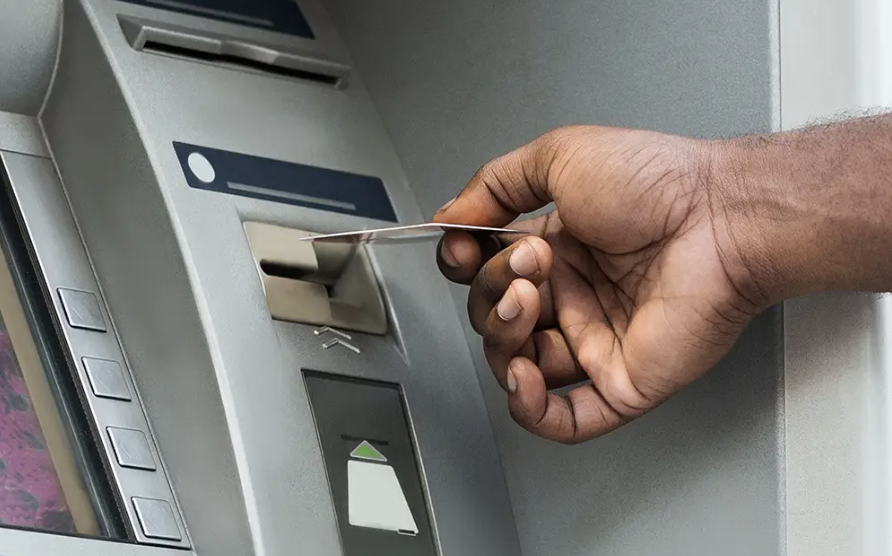
Furthermore, Norman also introduces the concept of a “conceptual model,” which represents the mental image users have of how an object functions. He underscores that a good design should align with users’ mental models to minimize confusion and enhance usability.
Think of ATM machines for instance. Our mental model when it comes to using this machine is card > money > card. This model was enhanced so that users take their cards before money, in order not to forget it. Now imagine if a random ATM machine decided to randomly function by card > card > money. It will definitely be confusing and may cause many users to lose their cards.
Finally, the chapter underscores the importance of providing feedback to users and making the system’s state visible. Feedback allows users to understand the consequences of their actions and provides a sense of control, a critical aspect of user-centered design.
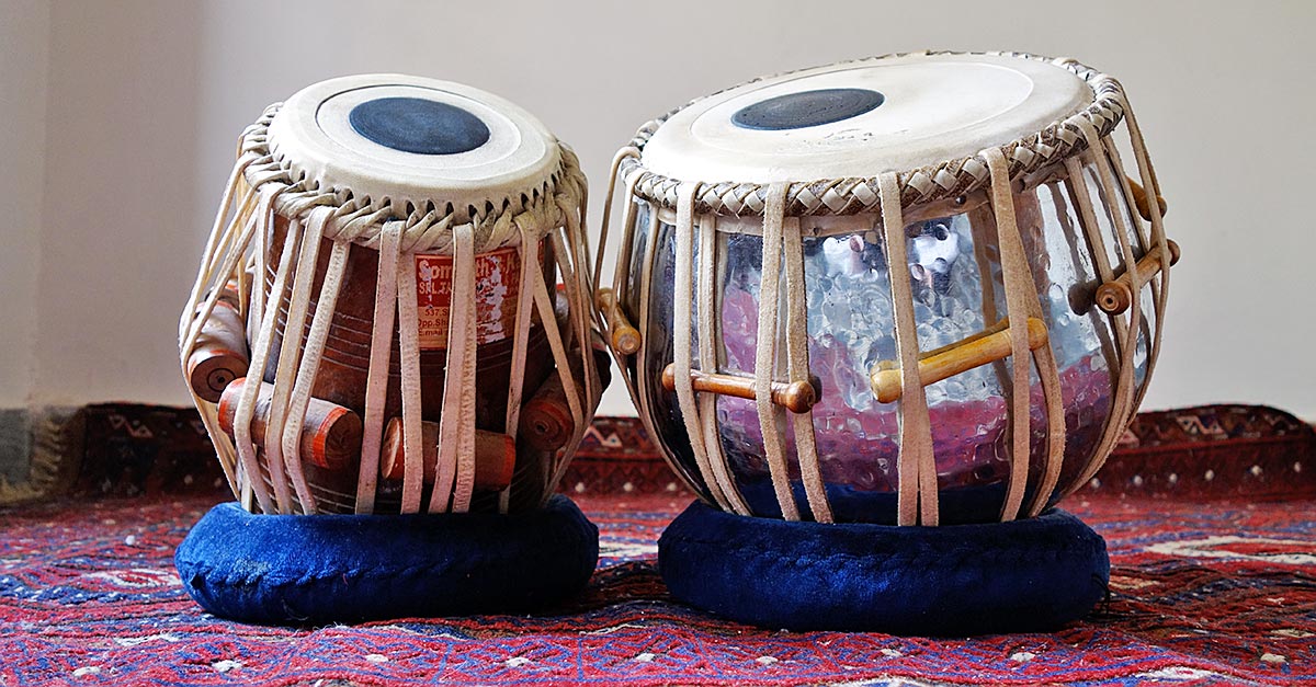
Khadija and I created a unique version of the tabla, a pair of hand drums commonly used in traditional South Asian music.
Initially, we thought of recreating the same instrument with the use of pressure sensor resistors but then we decided to make it light-sensitive. Our vision was to make the tabla come alive with an ethereal quality, allowing it to be played not by hand, but by the interaction of light. It was an interesting and fun project that resulted in a unique musical instrument.
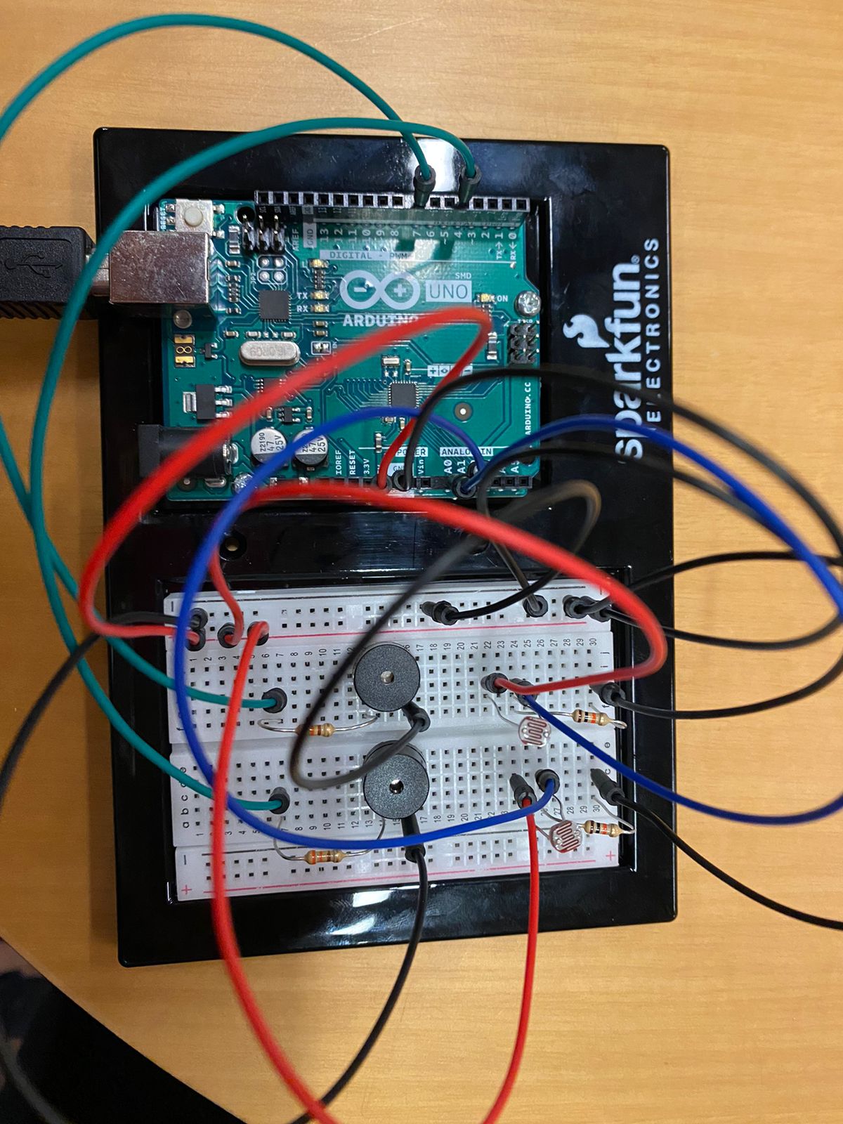
Initially, we began the project by connecting a single light sensor to a speaker. The main challenge we encountered was mapping the readings from the light sensor to play the correct melody from an array of notes. During the process of setting these thresholds, we decided to make the instrument turn off in bright conditions and start playing sound when the light sensor was covered by a hand in dimmer conditions. This approach created a similar hand action to that of hitting the tabla with the hand, resulting in a more authentic and natural playing experience.
After the initial phase, we decided to expand our project by adding another light sensor to take readings of the surrounding light. However, we faced a challenge when we realized that the changes in light conditions on the two light sensors were not being accurately reflected by the single speaker we were using. To solve this issue, we decided to divide the instrument into two separate speakers, with each speaker connected to one light sensor individually. This allowed for more distinct and clear sound production based on the readings of each light sensor.
For this assignment, I struggled to come up with a creative way of connecting a switch without the use of hands. So during one of my stress cleaning episodes in my room, when I tapped on my trash bin to throw something in, the light bulb went off in my mind. That’s why I created a switch that connects when the lid of the bin closes and the light turns on.
How it works
I used the following set up of the circuit. I connected two of the wires with tape because I needed more length for the wire attached to the lid of the bin. A coin is also taped at the end of this wire to increase the surface area of contact between this wire and the one attached to the rim of the bin.
Future improvement
For future implementations, I would somehow want the light to turn on when the lid is open instead and position the wires in a way that it does not disrupt the usage of the bin. Or maybe if a green light turns on if the bin is closed and red light turns on if bin is open.
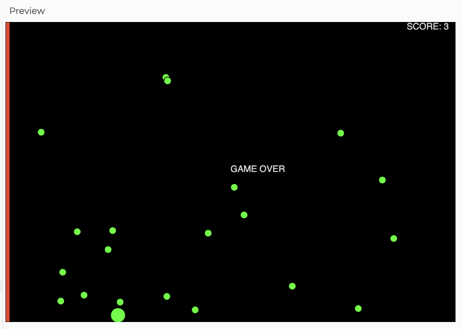
For my midterm project I’m creating a game called ‘Save the Snail’. It’s a very simple, easy-to-play game where the user tries to save a snail from getting eaten by a frog or getting hit by rocks.
Save the Snail:
The game will be extremely easy to play, and will just need a press on the keyboard or a click on the mouse. The frog will be at one end of the screen and the snail will keep getting attracted to the frog and the user’s click on the mouse will move the snail away to the right. At the same time there will be rocks falling randomly from the top of the screen and the user will also have to make sure the rocks don’t hit the snail. The gameplay overall is very simple. If the snail comes in contact with the frog or gets hit by the rocks, the screen shows the score and a game over message.
My Progress:
So far I have figured out how to make the rocks drop down randomly. I accomplished that using a class for the rocks and then a update() method to make them drop down. I also made the ‘snail’, currently it’s just a circle that keeps moving to the left and a built-in p5js function- mouseIsPressed()- moves the circle ten units to the right.
Here’s a screenshot of the progress. The code is still very scratchy and uncommented for the most part:
Things left to do:
Although the code is somewhat functional, what makes or breaks a game is the interface. I am looking to make the interface a lot more friendly and add graphical elements to it. Also, I’ll maybe try to add difficulty levels but I’m not sure if I can make that happen. For now the game is an arcade style game, a very good way to kill time, haha.
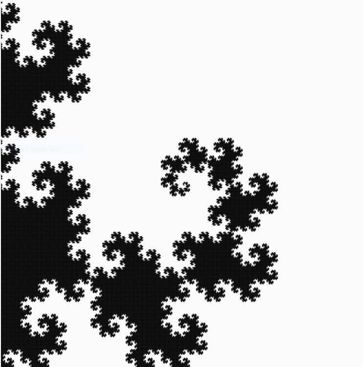
For this assignment, I have created multiple “glitchy” dragon curves, rotated with respect to the canvas center. The dragon curve is a widely known space-filling curve, meaning multiple of these curves can cover the entire 2D plane without overlapping. Not to mention, the curve is a fractal! I first encountered this curve in my freshman year in high school, and the experience was mesmerizing. For this reason, I decided to draw dragon curves as soon as I read the assignment description. Although the curve alone is indeed awe-inspiring, I added a glitchy appearance to the curves to make them look more interesting. The picture below is a single dragon curve without a glitchy appearance.
Code
I spent most of the time finding and coding an algorithm to create dragon curves. Fortunately, the algorithm was very intuitive because dragon curves are formed by “folding” a line segment 90° in left or right directions. I first declared an array (dirArr) that stores these directional data, which describes how line segments will be folded.
let dirArr = []; //Direciton Array storing Left or Right turn for each line segments
A function was created to fill this array using a recursive algorithm I have coded (1 indicates a right turn and -1 indicates a left turn). The default size of dirArr is 1, and it contains 1, meaning a right turn. As iteration number increases, dirArr will store more directional data, making curve more complex. The algorithm fills dirArr in this way:
Each array represents directional data stored in dirArr of different iterations.
For each iteration, the algorithm adds 1 at the end.
Then, directional data that were in the previous iteration’s dirArr (red) are copied into a temporary array.
Copied data in the temporary array are reversed (1 to -1 and -1 to 1). This data will then be added to dirArr in reverse order (blue).
Steps 1,2, and 3 will be done until given iteration of dirArris achieved (recursion).
function fillDirArr(iteration, myArr) {
  //Store Left or Right turns into dirArr. 1 = Right turn, -1 = Left
  count++;
  let tempArr = myArr.slice(); //tempary array to store dirArr
  myArr.push(1);
  let tempArrLength = tempArr.length;
  for (let i = 0; i < tempArrLength; i++) {
    let currDir = tempArr.pop(); //Read tempArr from the end
    myArr.push(-1 * currDir); //Reverse direction and push to currDir
  }
  if (iteration == count) {
    count = 0;
    dirArr = myArr;
    return;
  } else fillDirArr(iteration, myArr); //recursion until given iteration
}
Based on dirArr, lines will be drawn using a function. This function simply draws multiple line segments with a given length. One challenging part of drawing curves was letting the code know which direction is left or right. For example, when a line segment is heading upward, making a right turn and drawing another segment can be done by line(X,Y, X+length,Y). On the other hand, when a segment is heading leftward, making a right turn and drawing another segment can be done by line(X,Y,X, Y-length). As shown above, rotating a segment left or right turn must also consider a segment’s current direction. I solved this problem by using 1s and -1s as weights. Keeping track of the sum of 1s or -1s whenever a line segment turns allowed me to calculate the current direction of a segment. Simply draw lines in random directions and add up 1s or -1s depending on the direction of the turn. In the end, you will see the result to be:
0, when a segment is going up
1 or -3, when a segment is going right
-1 or 3, when a segment is going left
2 or -2, when a segment is going down
round(random(0,8*L)) was used to give the curve a glitchy look by slightly changing the ending coordinates of the lines.
function drawDragonCurve(X, Y, L) {
  let dirSum = 0; //1 or -1 act as "weights".
  for (let i = 0; i < dirArr.length; i++) {
    let currDir = dirArr[i];
    dirSum = (dirSum + currDir) % 4;
    if (dirSum == 0) {
      //UP
      //line(X, Y, X + L * currDir, Y);
      line(X, Y, X + round(random(0,5*L)) * currDir, Y);
      X += L * currDir;
    } else if (dirSum == 1 || dirSum == -3) {
      //RIGHT
      //line(X, Y, X, Y + L * currDir);
      line(X, Y, X, Y + round(random(0,8*L)) * currDir);
      Y += L * currDir;
    } else if (dirSum == -1 || dirSum == 3) {
      //LEFT
      //line(X, Y, X, Y - L * currDir);
      line(X, Y, X, Y - round(random(0,5*L)) * currDir);
      Y -= L * currDir;
    } else if (dirSum == 2 || dirSum == -2) {
      //DOWN
      //line(X, Y, X - L * currDir, Y);
      line(X, Y, X - round(random(0,5*L)) * currDir, Y);
      X -= L * currDir;
    }
  }
}
Reflection / Future Improvements
This assignment was very entertaining to work on because I have always wanted to make a dragon curve. Although the code required tons of logical thinking and calculations, I have managed to create a very satisfying digital art. When I finished the code, I was very happy to see my dragon curves filling my canvas without overlapping (when there is no glitchy effect).
My program seems to operate without any errors, but it needs optimization. Due to the complexity of the calculation using an array, the code is slow. For this reason, I removed the interactive aspect of the code. In the future, I would like to find a faster and more efficient way to draw dragon curves. When my code is finally fast, I would be able to make dragon curves to be interactive.
Before we began to work, we needed to sort out a grand variety of details. Which materials were we going use? How would we use them? When would we meet and build our project? Given that Lily is a senior and has her capstone paper due in less than 2 days, and her presentation a few days before the final submission, our team needed to make sure we were properly managing our time and planning realistic deadlines according to our schedule. We wrote a detailed outline with parts of our project and internal deadlines that we plan to keep in order to make our project the best final project. During this initial planning meeting, we also gave our project the name Dance Breaker. It is an ode to breakdancing AND hints to how the game will work: the music will stop (break) and you need to press the sensors to un-break it. Get it?
We also created our internal deadline system into google calendar and set working hours. Once we had our work cut out for us, we began the execution of our plan.
Building Progress
Game Mechanics:
We worked mostly on the P5.js code for the songs and serial connection. To do this he constructed a board with smaller sensors and pieces from a previous project that would allow for testing on a smaller scale. He also began to work with computer vision. The current p5.js sketch loads pixels and has a light threshold akin to previous class exercises. It took a long time to figure out how to mirror the image in order to have a comprehensive experience. Furthermore, he built conditional statements so that all sensors need to be pressed in order for a song to play. The arduino code should not require any changes after today except for the addition of the reward system.
Next steps for the game mechanics are:
Implement a functioning random timer (which was already created but not aligned with the music) to stop the song randomly and resume the game.
Randomize the sensors that need to be pressed in order for the music to continue.
Add a design to the computer vision beyond a threshold.
void setup() {
  Serial.begin(9600);

}
void loop() {
  int oneValue = analogRead(A0);

  int twoValue = analogRead(A1);

  int threeValue = analogRead(A2);

  int fourValue = analogRead(A3);

  int fiveValue = analogRead(A4);


    int sensorValue = oneValue;
    Serial.print(sensorValue);
    Serial.print(",");
    sensorValue = twoValue;
    Serial.print(sensorValue);
    Serial.print(",");
    sensorValue = threeValue;
    Serial.print(sensorValue);
    Serial.print(",");
    sensorValue = fourValue;
    Serial.print(sensorValue);
    Serial.print(",");
    sensorValue = fiveValue;
    Serial.print(sensorValue);
    Serial.println();
    delay(1);

  }
Physical Component: Dance Mat and Projector
We booked the necessary materials (a vertical projector, a camera) through the portal.
We also picked up the necessary sensors and acrylic to build our dance mats. We ran some simple tests with the materials in order to make sure that they work as imagined, and have begun to build the illustrator sketches for the laser cutting.
Next steps for the physical components are:
Finish the illustrator design and laser cut the materials
In week 8, we were given task which involved using Arduino and hardware. We had to create a unique & creative type of switch which could be operated without the use of our hands. By using this switch, we could turn the led on and off as required. So, I mainly learnt about building a simple led circuit using both the breadboard and resistor. I have built an aluminium foil-based switch platform separated by a non-conductive foam which is operated by force. So, the switch on happens by applying force on the platform.
IDEA:
I decide to make my own switch using conductive foils on cutted foam boards which was then separated by a non-conductive material. One side of the stranded wires were stuck to the foam board with the aluminium, using a clear tape and the other side of it which was stripped was connected with the jumper wires stripped using an electrical tape. At last, due to force, the terminals would come in contact with each other and circuit would be complete, thus LED would turn on and as the person stands up, the led would turn off.
INSPIRATION:
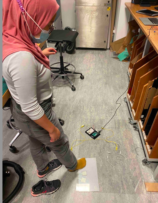
COVID-19 has become our new normal. Wearing masks, social distancing, constant use of cleaning wipes and sanitizers until our hands dry out is now integrated into our daily routines. This project was inspired by the COVID-19 regulations, specifically the social distancing requirement. In public seating, there is a required empty seat to be set empty between an individual and the person sitting next to them. What is currently being used are stickers and/or tape indicating on which seats it is permitted to sit. This project aims to improve this application. Every time someone sits on an undesignated seat, the LED lights up to tell the person to change their seat. This project’s purpose is to further develop and add technology to accommodate our new normal.
CHALLENGES & PROBLEMS:
The concept I had finalized for completing this task involved was the use of two aluminium foils which had to be wrapped around a carboard sheet and separated by a non-conductive material. Also, I had to find a way to stick the wires to the aluminium foil as soldering would not make them hold on the foil. Thus, since I had not worked on wiring and hardware much before, using the hardware was new for me. Another things I had to be very careful about is not to mix the +ve and -ve supplies as it could lead to the system getting damaged. The jumper wires were not fitting the Arduino board completely which made me put some force which bended some of them. So , now I take on the lesson that it only needs to be in-tact, no need to be fully on. To conclude, the entire process of sticking wire to the aluminium foil took a lot of time as the tape was not sticking to the foil. Thus, this was a very important process as without this, the switch won’t work for me, but eventually it all worked out.
PROCEDURE:
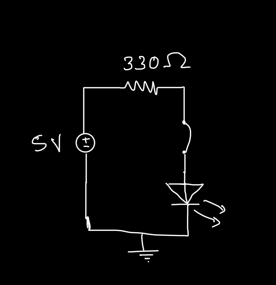
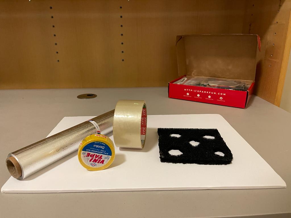
The first target was to blink an LED using Arduino and to do that I have gathered the following hardware:
Arduino board - LED - Resistor of value 330 Ohms -Jumper wires - USB Cable
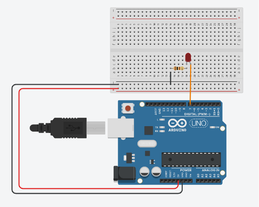
The circuit diagram which we referred was as following:
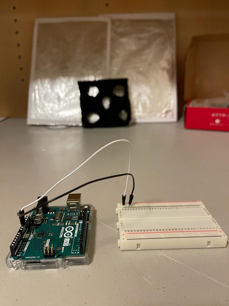
So, I used the hardware to power the + and – rails of the breadboard so that the entire circuit can use + and – from these rails if and when required in future connections. In the following image, the white wire goes into the +ve rail and the black wire goes into the -ve rail.
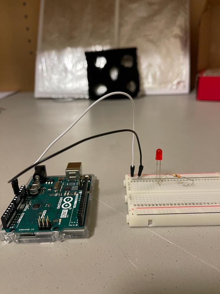
Next, we used a led, identified its Anode and Cathode (cathode has the shorter leg), and connected a resistor with it as shown. Resistor is used to limit the current through the led. We chose a value of 330 ohms as we read that led requires 20 – 25 mA of current for proper operation so resistor value of 100 ohms to 330 ohms work well.
Then I connected the other end of resistor to the ground to give it a -ve or GND signal
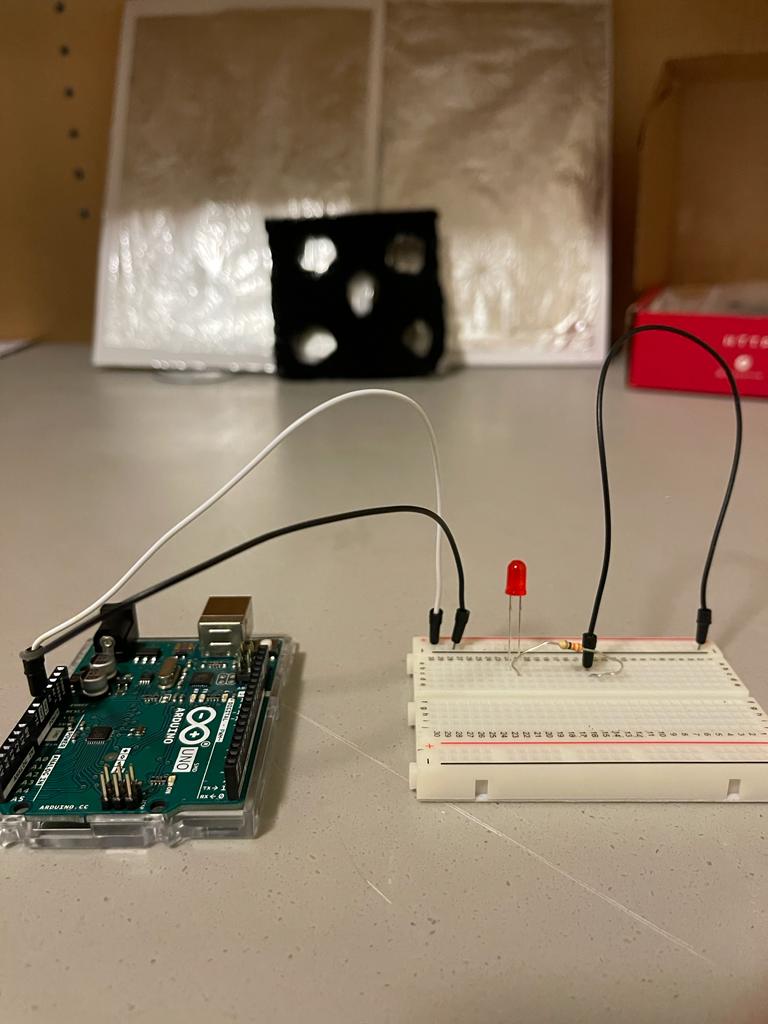
In this step, I connected the digital pin 7 from Arduino to Anode of led using a yellow jumper wire as shown.
Afterwards, I wrote a simple program to blink the led connected to digital 7 and uploaded it to our Arduino board by using the following settings on Arduino software. I selected usbmodem 143141 (Arduino Uno)
// C++ code
//
void setup()
{
  pinMode(7, OUTPUT);
}

void loop()
{
  digitalWrite(7, HIGH);
  delay(1000); // Wait for 1000 millisecond(s)
  digitalWrite(7, LOW);
  delay(1000); // Wait for 1000 millisecond(s)
}
Once the code was uploaded, we could see the led blinking on and off with a gap of 1000 ms
Once my LED circuit was complete, I started gathering material for making my own switching platform.
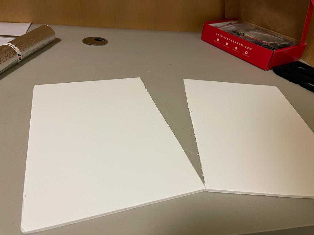
Next, I have cut the carboard in two different parts and these would serve as two different terminals of the switch.
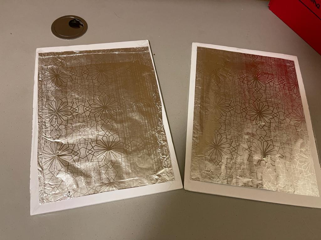
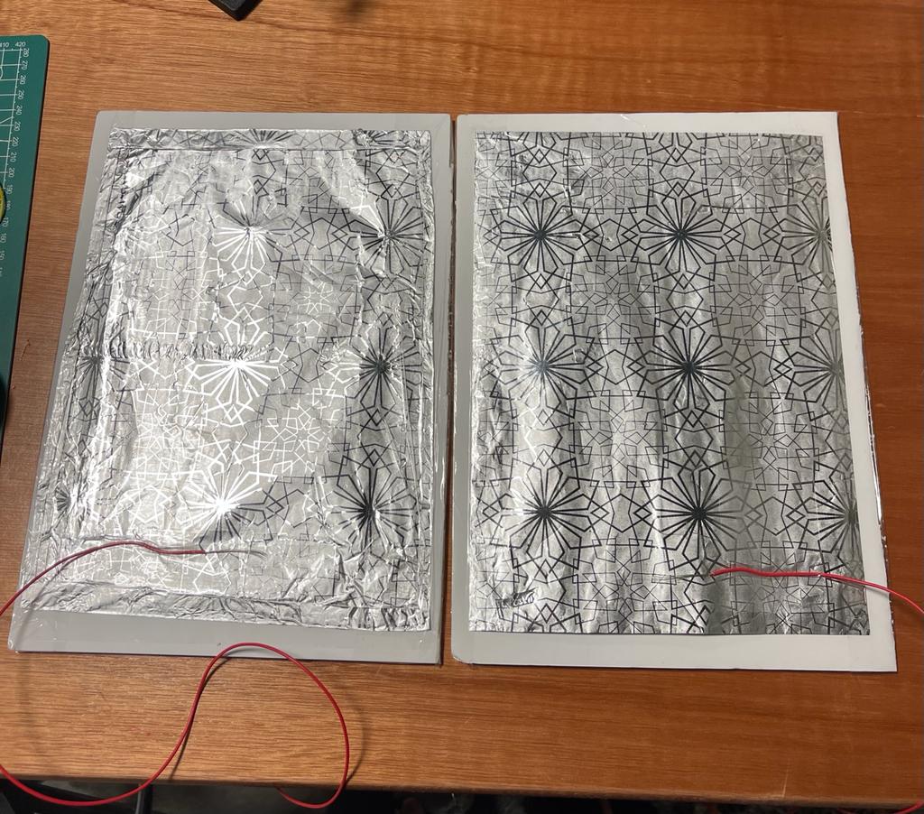
Then I used foil and put it on the foam cardboard using clear tapes as shown.
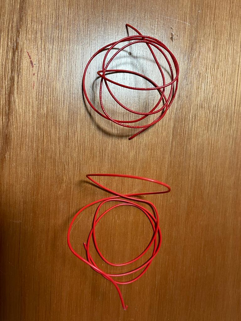
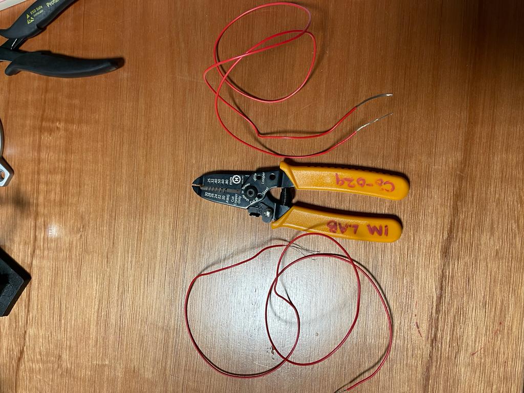
Now, I needed multi-strand wires to be connected to the foil. So, I used a single wire and cut it into two parts using a cutter, one for each foil board.
Using a wire stripper, both the ends of the two pieces of wires were stripped like shown
Afterwards, I used electrical tape to stick one end of each wire to the foil in such a way the wire strands were in contact with the conductive surface of the foil.
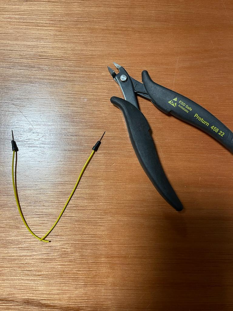
Later, I used a male-to-male jumper wire and cut it from middle using a wire cutter.
The other end of the wires taped to the foil was taped to male end of jumper wire as shown below.
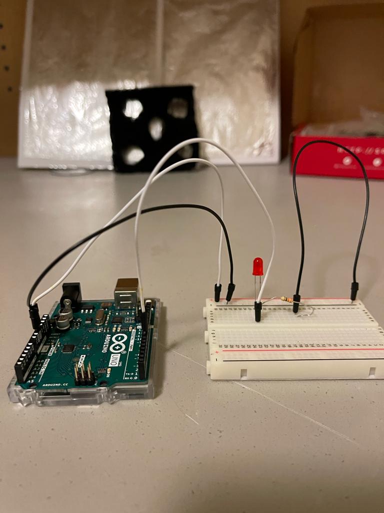
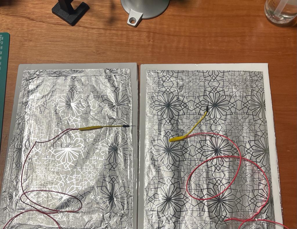
Now, I am ready to test my switch with my led circuit. I connected one foil arrangement to ground and the other was connected to a digital IO of Arduino as per my code.
The, I used the following code in my Arduino circuit and tested the foil switch which I made.
// C++ code

int led = 7;
int sensor = 6;

void setup()
{
  pinMode(led, OUTPUT);
  pinMode(sensor,INPUT_PULLUP);
}

void loop()
{
  if(digitalRead(sensor)==LOW)
  {
    digitalWrite(led, HIGH);
  }
  else
  {
    digitalWrite(led, LOW);
  }
}
So, I observed that the LED switched on once the two foils were made in contact with each other and switched off once the foils were separated which is how a switch works.
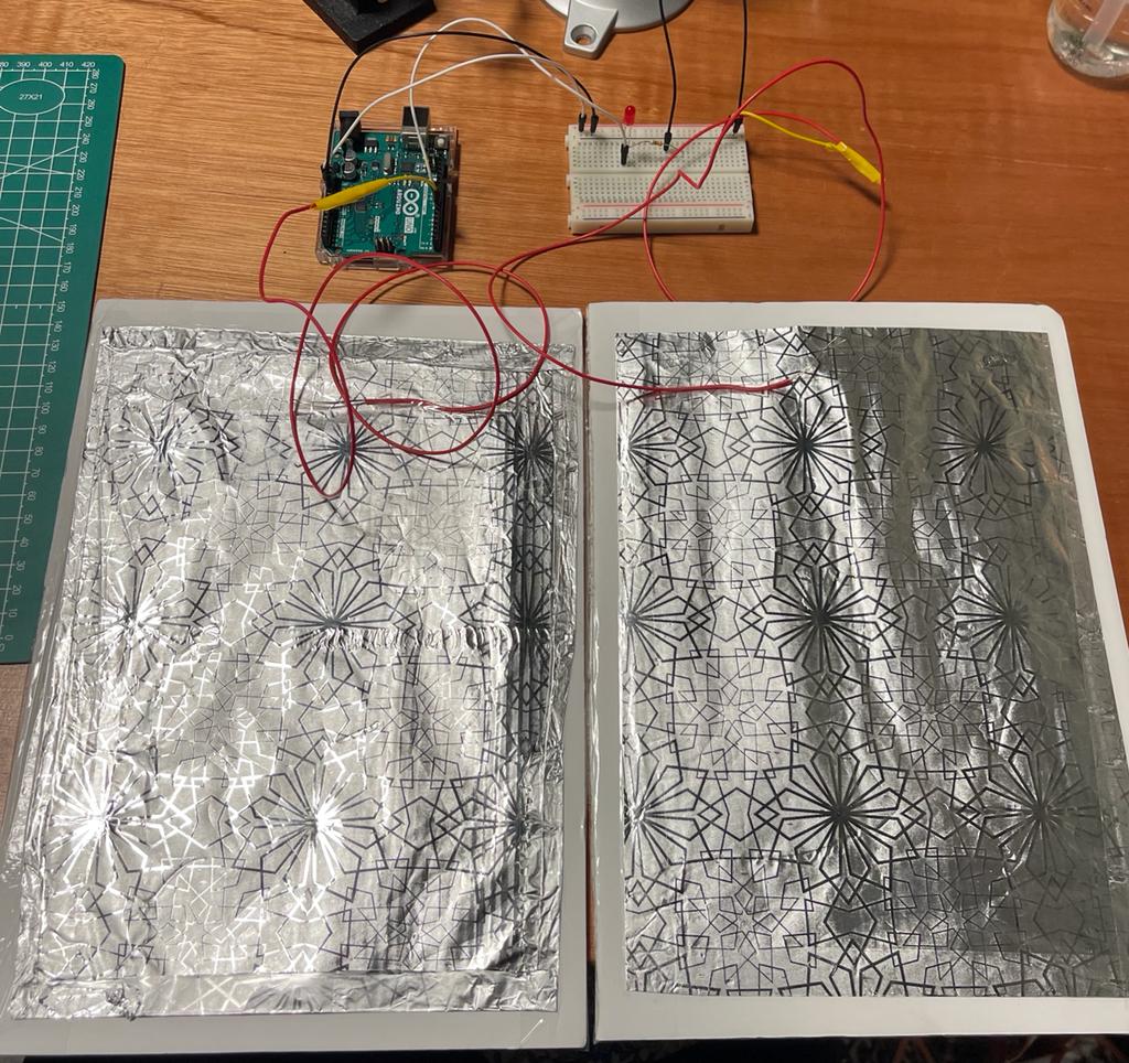
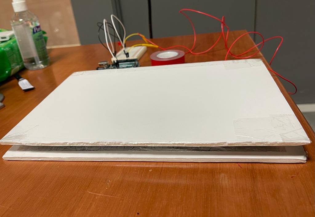
At the last step, I used the black non-conductive foam as a separator between the two foil boards and put everything together like a sandwich in which the non-conductive material ensured the foil would turn on only if someone puts force on the two boards. In this case the two foils would come in contact and the LED would turn on. The final arrangement looked like this.
FINAL WORK:
CONCLUSION:
There were a lot of ups and downs in this assignment, but I pulled it off at the end and had a great time exploring with the construction of my mini project. Furthermore, I will hopefully be taking this experience to achieve much more complicated tasks in the future.
HOPE YOU ENJOYED , HERE IS THE FULL CODE with the comments 🙂
// Shamma's Sit at your own risk Program
//C++ coding in Ardiuno

// Setting Global Variables
int led=7;
int sensor =6;


// This code runs only once
void setup()
{
  // only declaring input and ouput
  pinMode(led, OUTPUT); //  define the LED connected on pin 7 as an output

  // I did not use the input because it wont work properyly with what I builded
  // So,  input_pullup was used because it requires no external components and can be turned on & off in software during program execution
  //Another thing is that is it used to read switches properly and prevent missed readings
  pinMode(sensor,INPUT_PULLUP);// the proximity sensor acts as an input devide which will take an anction , in our case presnece of an obstacle
}


// This runs forever as long as system is turned on
void loop()
{
  if(digitalRead(sensor)==LOW)// reading if an obstacle (someone infront of sensor) is present
  {
    digitalWrite(led, HIGH);// turning on LED by giving the anode of LED +5 volt signal

  }
  else
  {
    digitalWrite(led, LOW);// if no one is present, turn off LED by giving low signal
  }
}