
This project is about potentiometer and LED lights. When you press the certain parts of potentiometer, the matched LEDs will be on. In this circuit, I divided the potentiometer into three parts according its shape are the top, middle and bottom.
All Posts
LightPulb
I spent a while refreshing on the coding we learned the other day, and found the part that involves sensors most intriguing. I tried analog input with the potentiometer, flex sensor, and photocell. I also asked Scott about the RGB LED and tried it with switches on my board. But all this review work didn’t really give me an idea what to do for the assignment. So I looked closely at the shelf full of electric parts, and found this magic stuff:
Mood Ring
What My Project Does:
For this project I used an RGB light and the temperature sensor to create a simplified version of a mood ring. When the user touches the temperature sensor, the sensor detects a certain temperature that correlates with an output RGB color that could be associated with someone’s mood. The red indicates that person is very warm, possibly happy, and energetic. Green indicate the person is stable, under normal conditions. Blue, finally, indicates the person is cold from air conditioning, or is just feeling bitter that day.
How I Did It:
I read up the Arduino site figure out how to get the temperature sensor to spit out a number that correlated with temperature. When I was able to find the code online on how to get an output number from the sensor, I found specific ranges to use when determining when the specific color would turn on.
The red color turns on when the output voltage reads above 0.80. The green turns on between 0.78 and 0.80. Finally, anything below 0.78 is blue. These are all correlated to temperatures between 24° and 26° Celsius.
For the temperature coding, essentially I used a code that would take a floated number retrieved from the A0 pinhole, and then that number, when multiplied by 0.004882814 (as I found online), produces the voltage number. Within my loop function, I assigned the variable ‘voltage’ to the voltage number received by the sensor. This number then, when subtracted from 0.5 and multiplied by 100 (again, as I found online), was the equivalent to degrees Celsius. I then had the voltage and degrees C° printed in order to find the ranges for the lighting and to make sure the sensor was outputting stable numbers. At one point, the sensor I was using overheated and started outputting the temperature as -25°, so when I changed it out for another sensor it worked fine.
That’s a brief explanation of how the coding works. Below is the code with a few bits of commentary on what the coding means, followed by a video and set-up photo.
const int temperaturePin = 0;
int red = 11; //these correspond to the RGB pinholes
int green = 10;
int blue = 9;
void setup(){
  Serial.begin(9600); //For the sensor, this is the initial baud rate needed to match the speed of the code I'm running
  pinMode(red,OUTPUT);
  pinMode(green,OUTPUT);
  pinMode(blue,OUTPUT);

}
void loop() {
  float voltage, degreesC;

  voltage = getVoltage(temperaturePin); //(see below for the function that retrieves the voltage

  degreesC = (voltage - 0.5) * 100.0; //conversion of voltage to degrees

  Serial.print("voltage: "); //printing the voltage and corresponding degrees C
  Serial.print(voltage);
  Serial.print("  deg C: ");
  Serial.println(degreesC);
  delay(1000);

  if(voltage > 0.80){ //for warmer temperatures, the light turns on as red
  digitalWrite(red,HIGH);
  } else {
    digitalWrite(red,LOW);
  }
  if(voltage > 0.78 && voltage < 0.80){ //for stable room temperature, the light turns on green
    digitalWrite(green,HIGH);
  } else {
    digitalWrite(green,LOW);
  }
  if(voltage < 0.78){
    digitalWrite(blue,HIGH); //blue light for cooler temperatures
  } else {
    digitalWrite(blue,LOW);
  }

}

float getVoltage(int pin)   //This takes the A0 input and floats the number
{

 return (analogRead(pin) * 0.004882814); //the A0 number is multiplied by this to retrieve the voltage
}
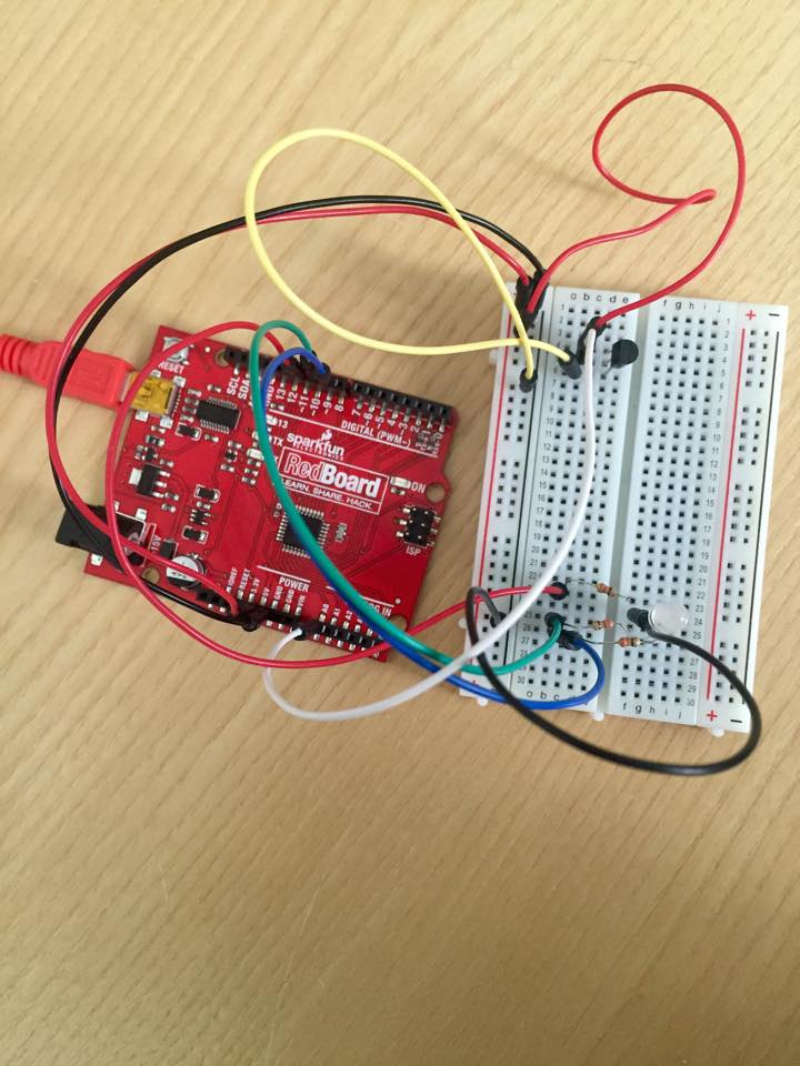
Setup of RedBoard:
All Da Colors
All Da Colors! This fun little creation allows you to switch color to color as well as their combinations as you turn the potentiometer! Check it out in action!
Unlock the Lights
Based on last week’s circuit, I wrote a new program to make it into a digital lock. The main idea is that if you press the buttons in the correct order, all three lights will light up (unlocked). I set two sets of password by incorporating potentiometer into my circuit.
The circuit on the breadboard is pretty similar to what I did last week. The only difference is the set up of the potentiometer. The potentiometer is connected to power, ground and analog input A0. When the voltage at A0 is below or equal to 512 volts, we use one set of the password. When the voltage at A0 is above 512 volts, we then use another set of the password.
Joy(stick)!
Given that our task was to fiddle with analog inputs, I figured I could just experiment and do cool stuff using a joystick – also known as an analog stick for a reason. In the end, I connected a joystick to a breadboard in order to control the pitch of a buzzer and the color of an RGB LED!
Make sense of the world
We were talking last time about how awesome computers are at reconfiguring themselves to do different things. This was manifest in pins on the microcontroller that we could change the behavior of through software.
What we were lacking in this model though, something that we possess, is a sense of memory (regret, if you must). Our programs so far forget things as soon as we’re done with them. It’s not a very efficient method, like buying a new water bottle everytime you wanted a drink. Instead, let’s save the planet and use something over and over again. In programming, the tool we can use for this is a variable.
RGB–Color Control
In this project, I made a circuit with three digital inputs and three digital outputs. There are three switches with different colours and three different colours’ LED lights. Red and green switches together can control the blue LED lights, red and blue switches together control the green LED lights, and the blue and green switches control the red LED lights. If you push the three buttons at the same time, all lights will be on.
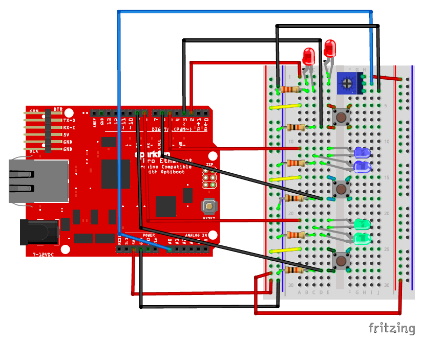
It’s all about patterns
When I thought about the assignment this week, the most obvious way of combining several switches and LEDs seems to be matching them by their colors. But I don’t want to make it boring and just connect components of the same color together. Instead, I created a pattern of lights. What I did was that I placed LEDs and Switches in the opposite order( Red, Yellow, Green, Blue and the reverse) on the breadboard, and made the switches control the blinks of their same-color LEDs, at the same time turn off the adjacent light. Here are the diagram and photo of the layout:
Will it turn on?
The video of my project working can be found here. My board works as follows. If I press the first switch, I do not know a priori if the lights will turn on. If I press the second and the first together, the lights will turn on with 100% probability. To randomly turn on the light when the switch is activated, I create two random numbers. The Arduino documentation doesn’t say how its random numbers are distributed, but I assume that they are uniformly distributed between the min and max arguments to the random function. With the two random numbers in hand, I perform a test to see if the first is larger than the second. If it is, then the lights will turn on if the switch is activated. If not, then the lights won’t turn on. The code for my loop() function can be seen here.