
This project is about potentiometer and LED lights. When you press the certain parts of potentiometer, the matched LEDs will be on. In this circuit, I divided the potentiometer into three parts according its shape are the top, middle and bottom.
Potentiometer Controls LED Lights
The key point in making this project is to control the range of voltage of potentiometer. When I got the number of the the number of voltages’ boundaries, we can start.
The first step — Record the numbers I need to use.
/*
  Analog input, analog output, serial output

 Reads an analog input pin, maps the result to a range from 0 to 255
 and uses the result to set the pulsewidth modulation (PWM) of an output pin.
 Also prints the results to the serial monitor.

 The circuit:
 * potentiometer connected to analog pin 0.
   Center pin of the potentiometer goes to the analog pin.
   side pins of the potentiometer go to +5V and ground
 * LED connected from digital pin 9 to ground

 created 29 Dec. 2008
 modified 9 Apr 2012
 by Tom Igoe

 This example code is in the public domain.

 */

// These constants won't change.  They're used to give names
// to the pins used:
const int analogInPin = A0;  // Analog input pin that the potentiometer is attached to

int sensorValue = 0;        // value read from the pot

void setup() {
  // initialize serial communications at 9600 bps:
  Serial.begin(9600);
}

void loop() {
  // read the analog in value:
  sensorValue = analogRead(analogInPin);


  // print the results to the serial monitor:
  Serial.print("sensor = " );
  Serial.println(sensorValue);

  // wait 2 milliseconds before the next loop
  // for the analog-to-digital converter to settle
  // after the last reading:
  delay(2);
}
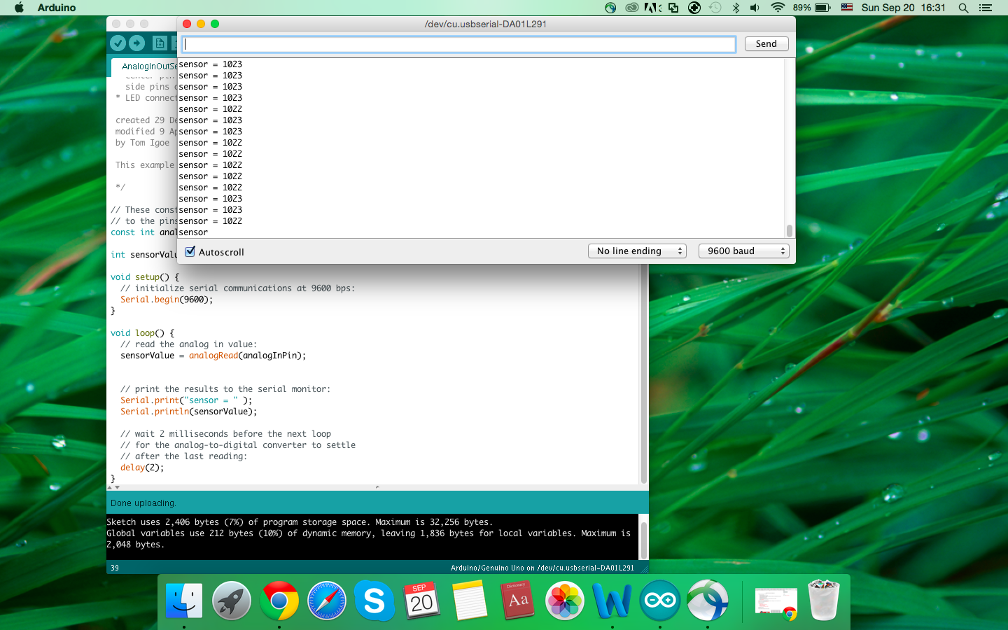
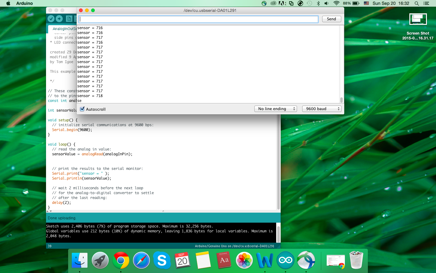
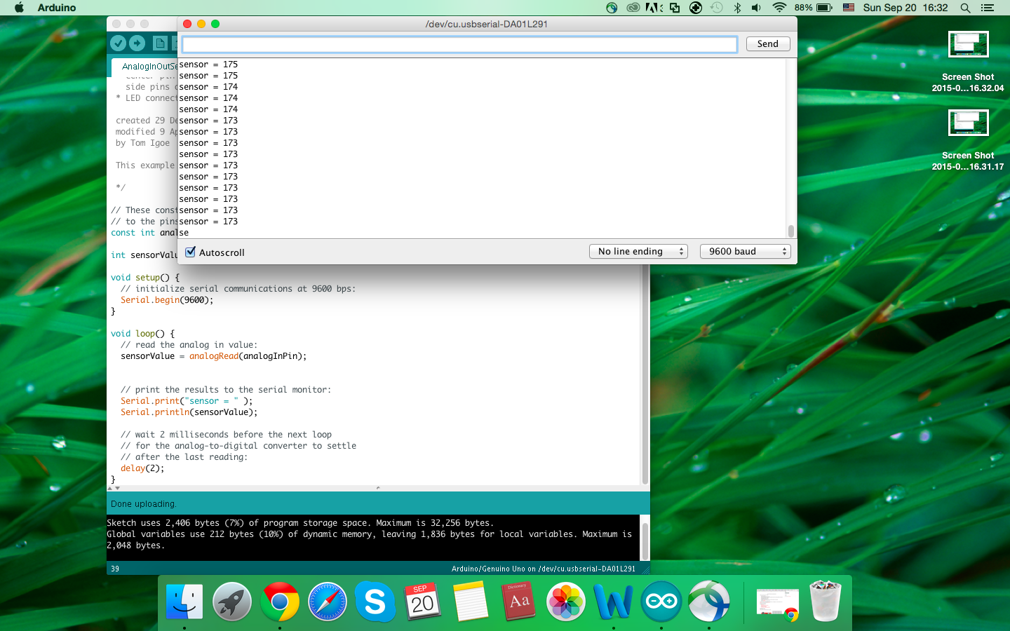

When I press the different part of the potentiometer, the numbers of the voltage are different. From the top to the bottom of the potentiometer, the number changes from 1023 to 0. So I divide the potentiometer into three parts in my mind. For the top part, I give it the value range from 1023 to 513. The middle part is from 512 to 261. The bottom part is from 261 to 1. Actually, I have changed these ranges came from the test because the potentiometer is not delicate enough to show the original value. After several experiments, I choose the numbers in the next code.
int sensor = A0; // the value of sensor
int sensorVal;

void setup() {
  // put your setup code here, to run once:

  pinMode(2, OUTPUT);  // the LED red
  pinMode(3, OUTPUT);  // the LED yellow
  pinMode(4, OUTPUT);  // the LED green
  Serial.begin(9600);
}


void loop() {
  // put your main code here, to run repeatedly:
  sensorVal = analogRead(sensorVal); // the sensor
  Serial.println(sensorVal);

  if (sensorVal >= 1 && sensorVal <= 260) {
    digitalWrite(2, HIGH);
    delay(200);
    digitalWrite(2, LOW);
    delay(200);

  } else if (sensorVal >= 261 && sensorVal <= 512){
    digitalWrite(3, HIGH);
    delay(200);
    digitalWrite(3, LOW);
    delay(200);
  } else if (sensorVal >= 513 && sensorVal <= 1023) {
    digitalWrite(4, HIGH);
    delay(200);
    digitalWrite(4, LOW);
    delay(200);
  } else {
    digitalWrite(2, LOW);
    digitalWrite(3, LOW);
    digitalWrite(4, LOW);
  }
  delay(2);
}
When I press the top part of potentiometer, the green LED will be on. When I press the middle part, the yellow LED will be on. When I press the bottom part, the red LED will be on. To make the circuit better, Scott also helped me add two capacitors in it. Thank you~