Christmas is in the Air
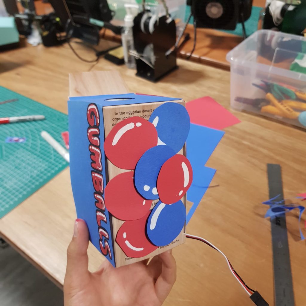
Concept:
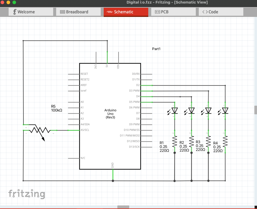
Christmas is growing closer by the day, and where’s the festive mood without some carols? In this project, we are using switches, a piezo buzzer, and a potentiometer that has the five notes needed to play Jingle Bells. Switches 1 through 5 represent nodes C5, D5, E5, F5, and G5 in order. The LED on pin 13 lights up when you switch between nodes. The potentiometer lets you control the tempo. If you are not familiar with the notes, you follow the order below to play the song.
%%%%%%%%%%%
3,3,3
3,3,3
3,5,1,2
3
4,4,4,4,
4,3,3,3,3
3,2,2,3
2,5
%%%%%%%%%%%
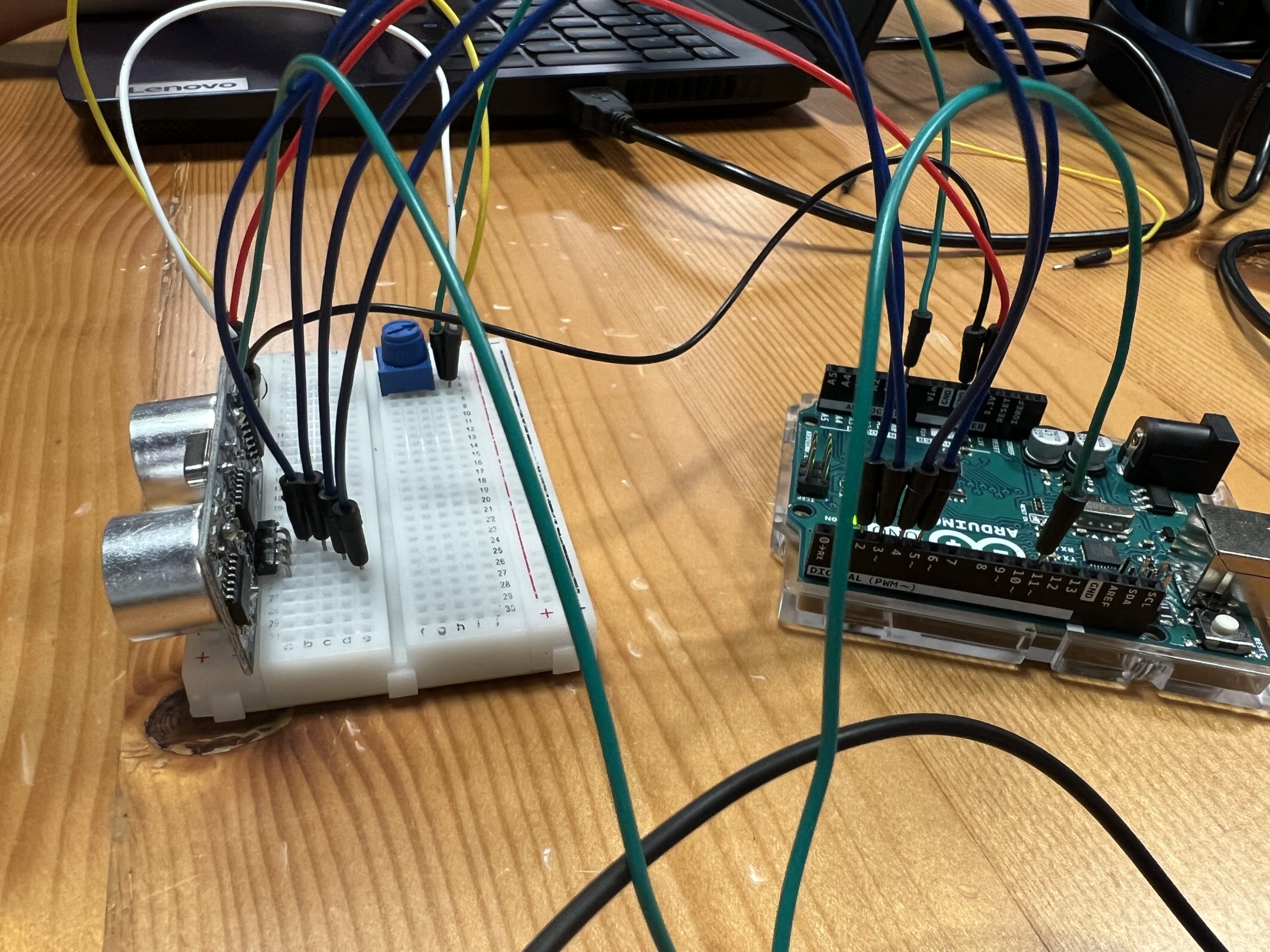
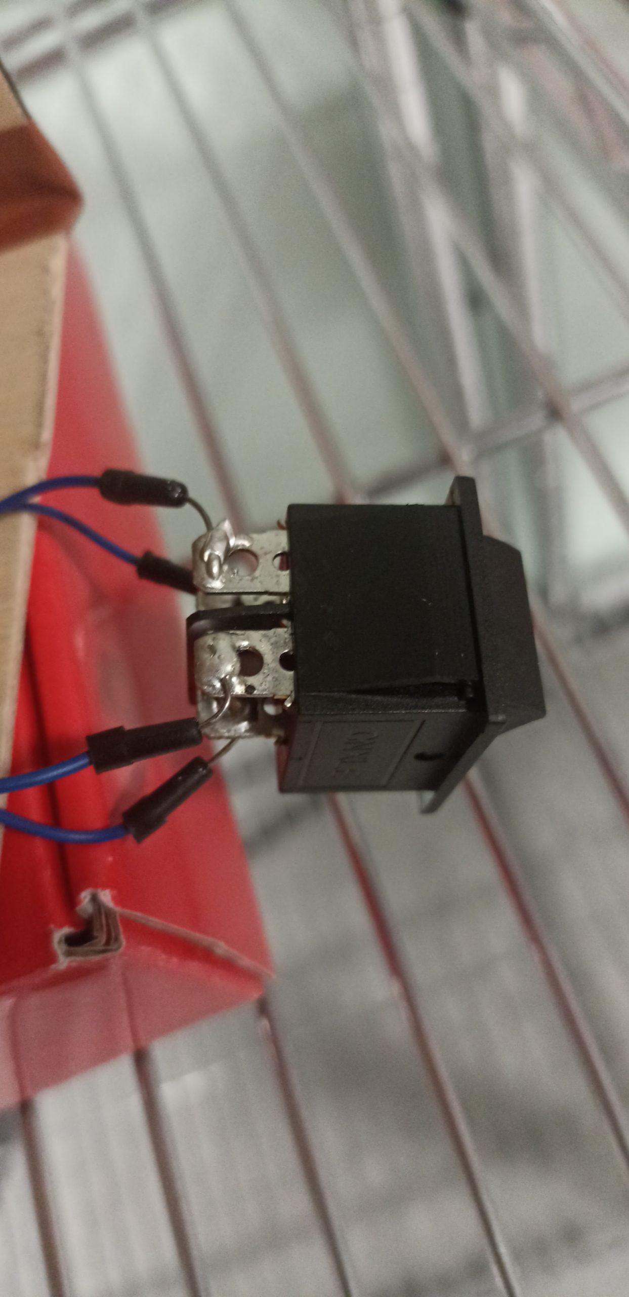
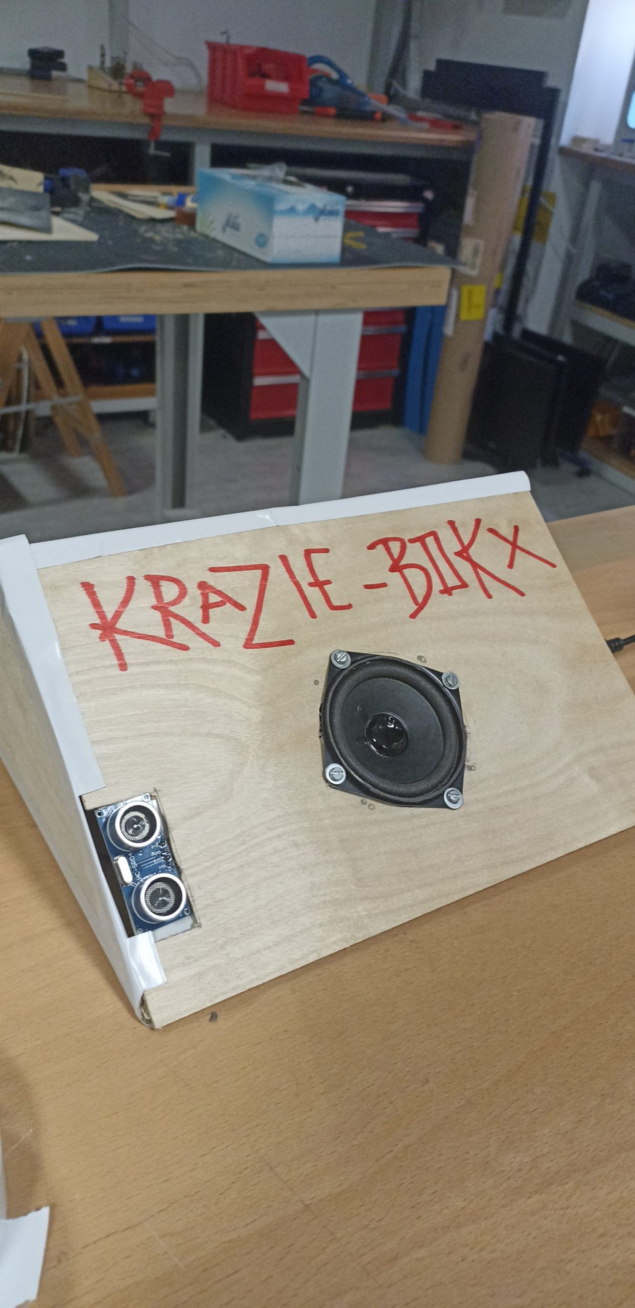
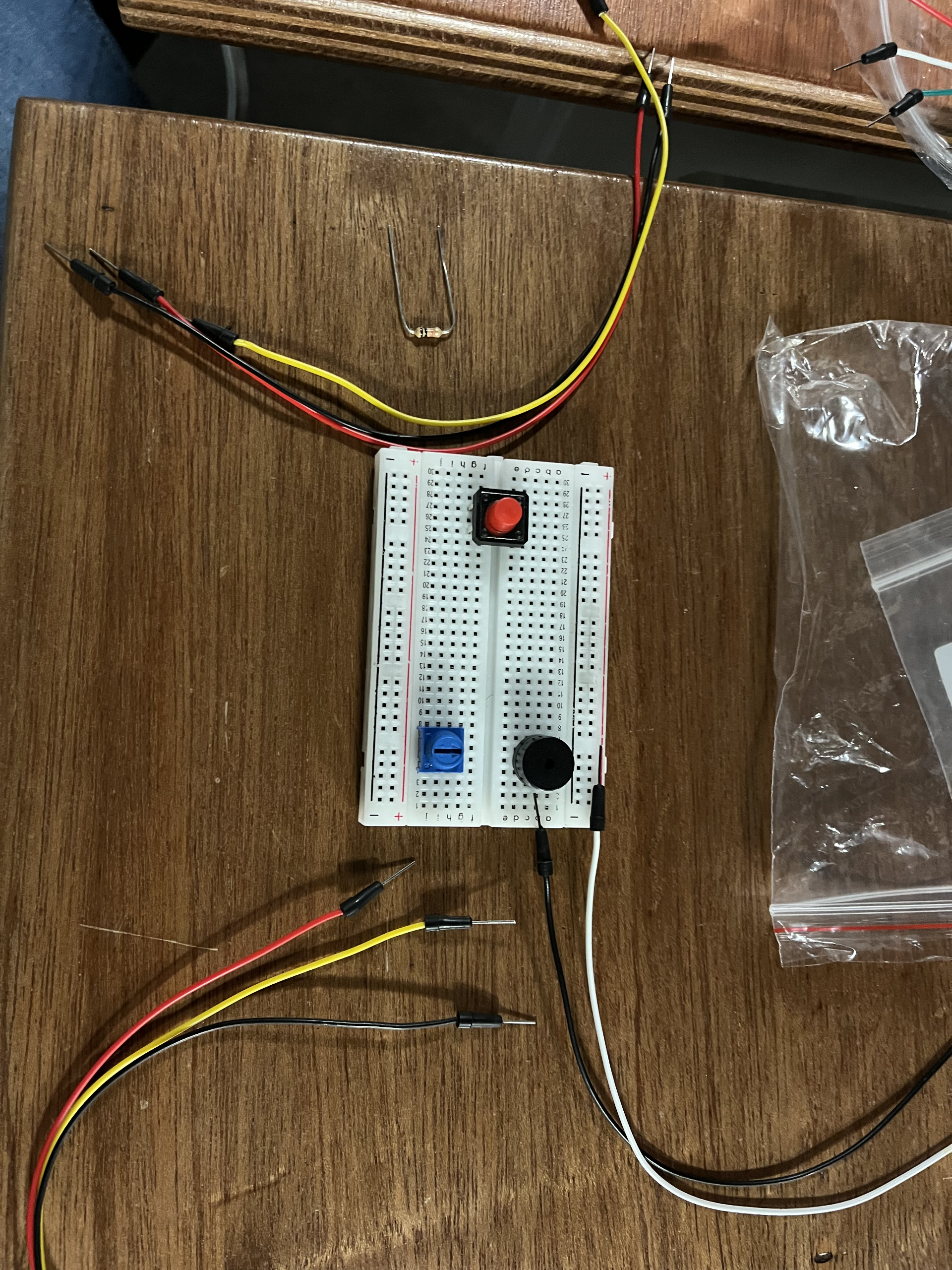
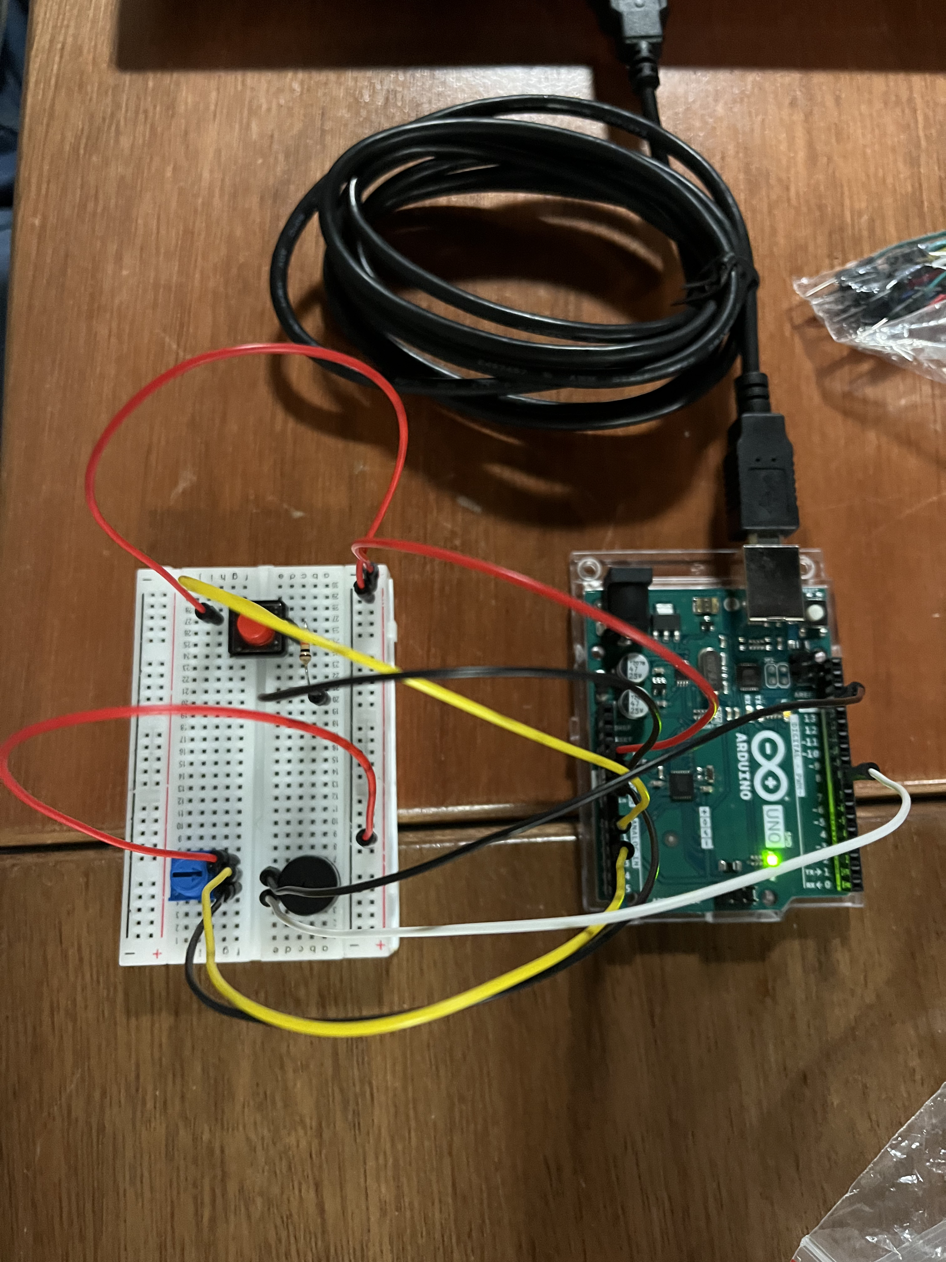
The Switches:
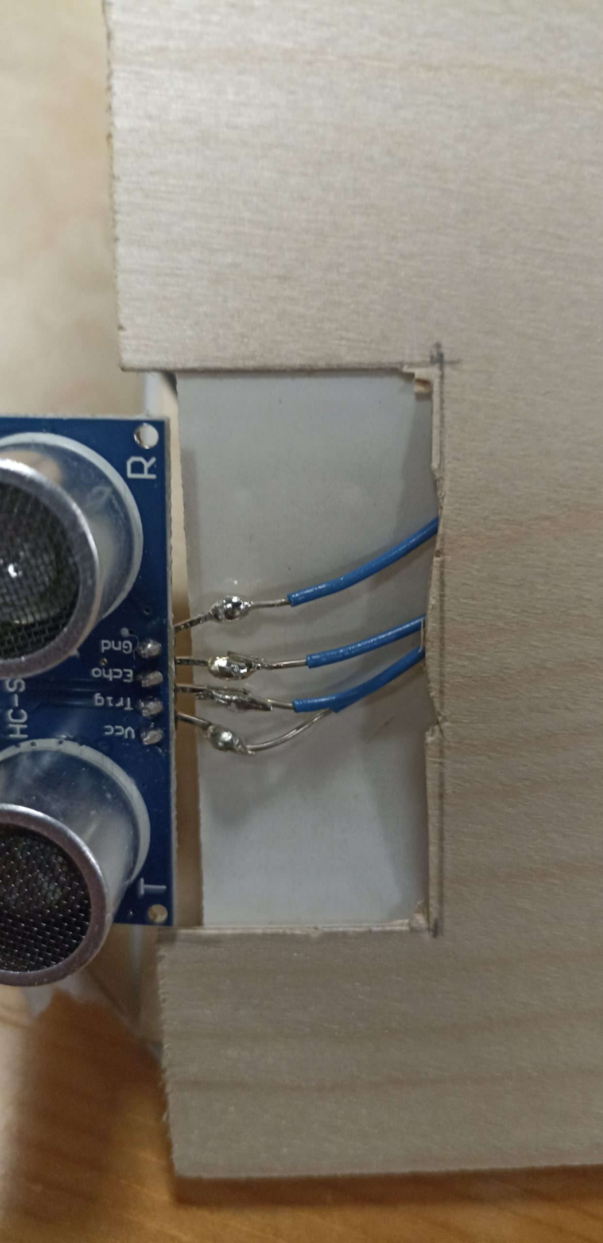
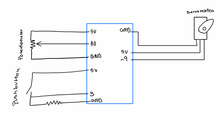
In the beginning, we thought about using distance measurement sensors. We would then map different nodes of the song to the numbers we read from the sensor in a way that the tempo would increase and decrease as you get closer or farther from the sensor. But we wanted defined and distinct sounds and a more exact mapping so we decided to go with a digital I/O instead. We were also aiming to use the potentiometer to control volume initially but the buzzer was acting strange with the signal change in the potentiometer. Later we figured it was better and more practical to control the tempo via a potentiometer (the default tempo is 8).
The five nodes in the program C5, D5, E5, F5, and G5 are defined in “pitches.h”. The song sheet is converted to code taken and provided by Project Hub and there is also a tutorial on how to do it yourself by Nathan Seidle on Github.
// %%%%%%%%%%%%%%%%%%%%%%%%%%%%%%
void loop() {

  int knob = analogRead(A2);
  Serial.println(knob);

  tempo = map(knob, 0, 1024, 60, 255)/15;

  switchOne = digitalRead(2);
  switchTwo = digitalRead(3);
  switchThree = digitalRead(4);
  switchFour = digitalRead(5);
  switchFive= digitalRead(6);

  if (switchOne == HIGH) {
    sing(1);
  } else if (switchTwo == HIGH) {
    sing(2);
  } else if (switchThree == HIGH) {
    sing(3);
  } else if (switchFour == HIGH) {
    sing(4);
  } else if (switchFive == HIGH) {
    sing(5);
  }
}
// %%%%%%%%%%%%%%%%%%%%%%%%%%%%%%
Full code on p5.js can be found here.
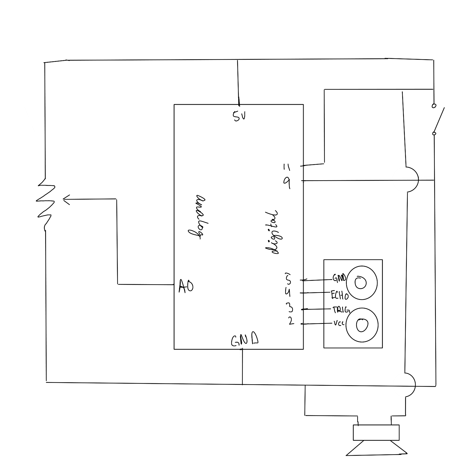
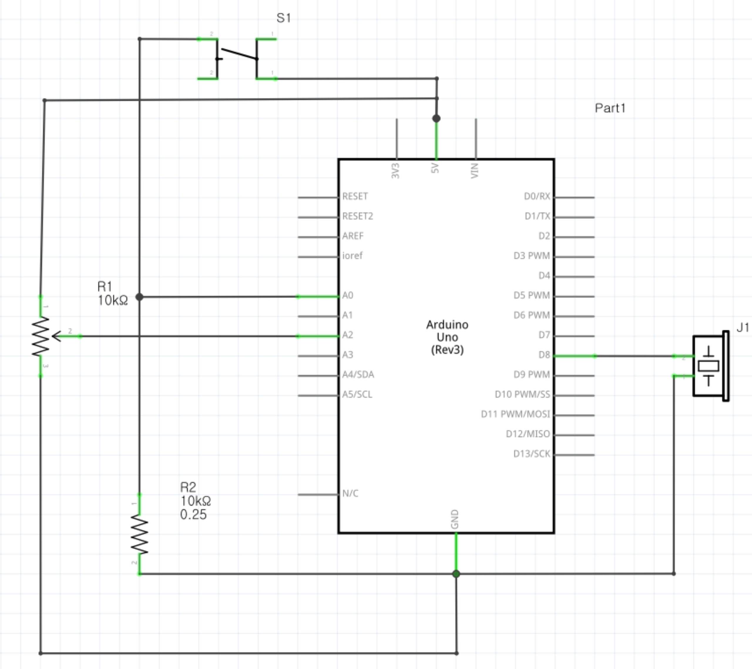
The Potentiometer:
After realizing that using the potentiometer for volume control would be difficult to do with our buzzer, we decided to use it as a means to control the tempo settings (the length of each note) of our instrument. This part of the code is used to achieve this:
void loop() {
//Potentiometer Value is Assigned to knob
  int knob = analogRead(A2);
//Tempo is Remapped and Divided
  tempo = map(knob, 0, 1024, 60, 255)/15;
. . .
//Tempo is Used to Determine Note Duration
  int noteDuration = 1000 / tempo;
  tone(melodyPin, c5, noteDuration);
}
With each loop, the value of the potentiometer is read and updated to the integer knob, which is subsequently remapped and divided; this value is then called to calculate noteDuration, which is used as a parameter that determines the length of the note played though tone(). According to this code, turning the potentiometer clockwise increases the length of a single note, while turning it counterclockwise achieves the opposite. With the potentiometer set up, our project can emit tones of differing pitches and lengths, allowing us to play neat little songs like Jingle Bells!
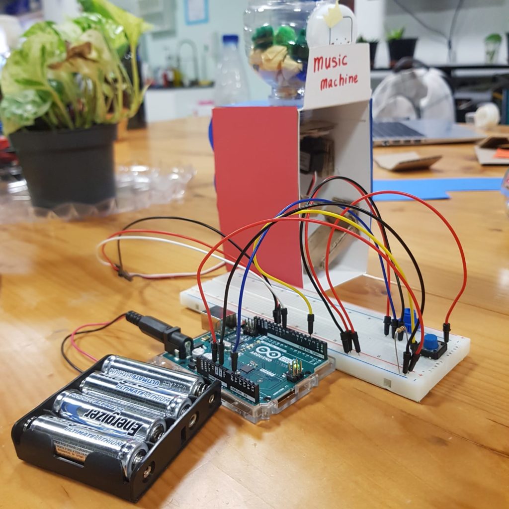
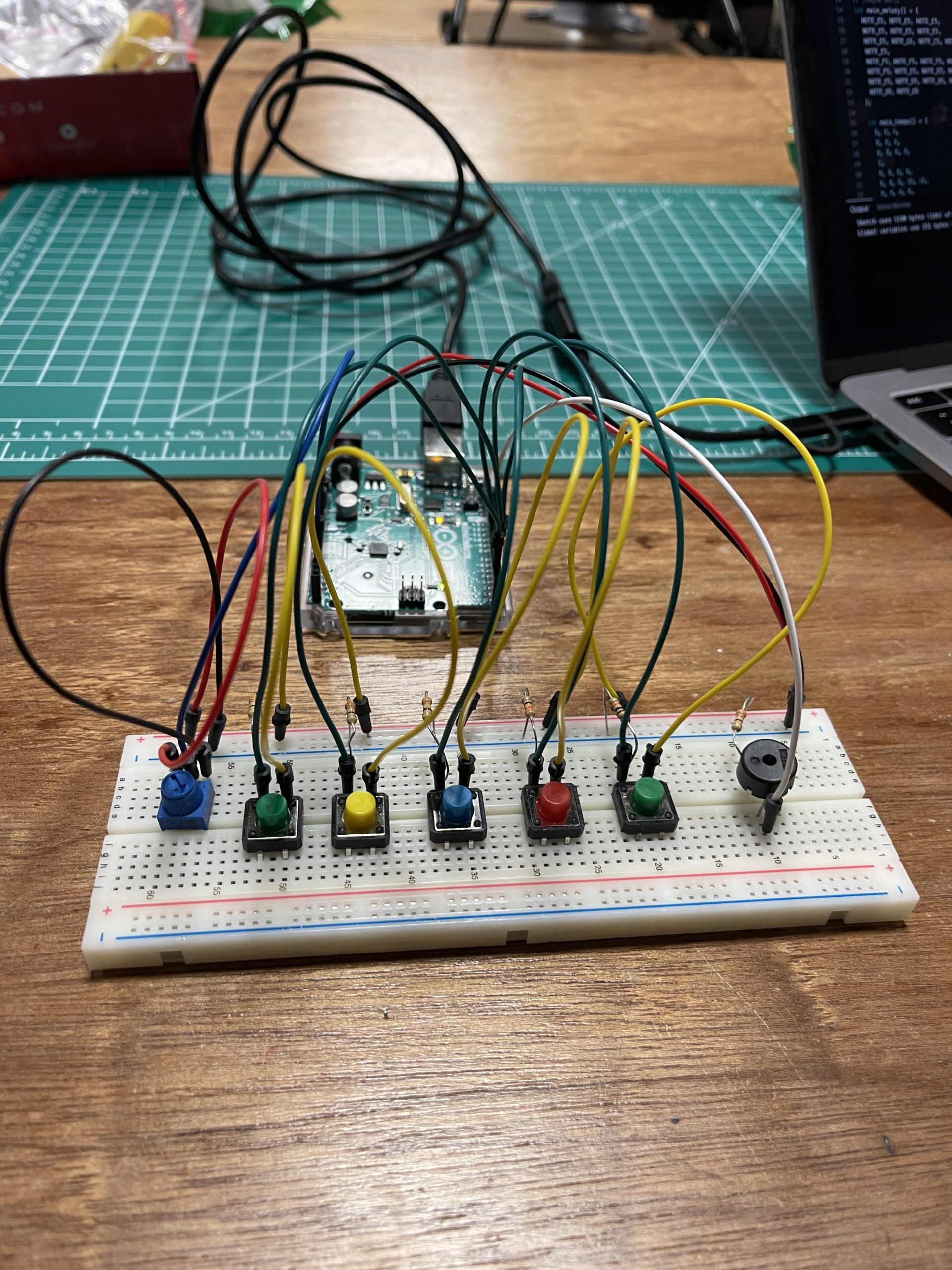
Demo:
Reflection:
It was an enjoyable and rewarding experience to brainstorm and collaborate on this project as a group! It definitely helped to have each other to consult (and commiserate with) when we were stuck at certain points. If we were to have more time, we would have liked to decorate our instrument with LEDs that correspond to the notes being played; regardless, we’re very proud with what we were able to achieve with this project. With each project, our familiarity with Arduino grows—and in this case, so did our teamwork. Coupled with a nice carol, this project really harnesses the Christmas spirit!