Concept:
I often use my phone late in the night with my light out and this has been messing up my eyesight for this Project I decided to create a form of eye protection warning system that alerts the user with the use of an LED when the light from their phone screen or laptop is too bright.
So when the screen brightness is low the LED remains off and as the user increases the brightness the LED gets brighter. When the screen brightness reaches a level where the user’s eye is at harm the LED starts to blink and when the brightness gets too high the LED blinks faster.
Code:
int warning=0;//variable to store the warning value used to control blinking and led brightness

void setup() {
  // put your setup code here, to run once:
  pinMode(13,OUTPUT);//set the 13 pin to output type
  pinMode(8,INPUT);//set pin 8 to input type
  pinMode(6,OUTPUT);//set pin 6 to output type
  Serial.begin(9600);//set serial screen for viewing values
}

void loop() {
  // put your main code here, to run repeatedly:
  int anasens=analogRead(A2);//read info from light sensor and store in anasens

  int digsens=digitalRead(8);//read info from switch sensor and store digsens
  Serial.println(anasens);//print anasens on serial board
  anasens=constrain(anasens,100,680);//keep the values between 100 and 680 at all times
  warning=map(anasens,100,680,0,255);//rescale the values from 100 and 680 to 0 and 255

  if(digsens==1){//if the switch is pressed
    digitalWrite(13,1);//turn on yellow LED
  }
  else{//if the switch is not pressed
    digitalWrite(13,0);//turn off LED
  }
  if(warning>200){//if the warning is greater than 200
    analogWrite(6,warning);//turn on red LED based on warning value
    delay(100);//wait for 100 milliseconds
    analogWrite(6,0);//turn off red LED
    delay(100);//wait for 100 milliseconds
  }
  if(warning>100&&warning<200){//the value is between 100 and 200
    analogWrite(6,warning);//turn on red LED based on warning value
    delay(500);//wait for 500 milliseconds
    analogWrite(6,0);//turn off red LED
    delay(500);//wait for 500 milliseconds
  }
  analogWrite(6,warning);//turn on red LED based on warning value
}
Highlight:
This was an interesting assignment. I am happy I was able to do it. What i look forward to is making this a wireless connection as connecting the wires was stressful
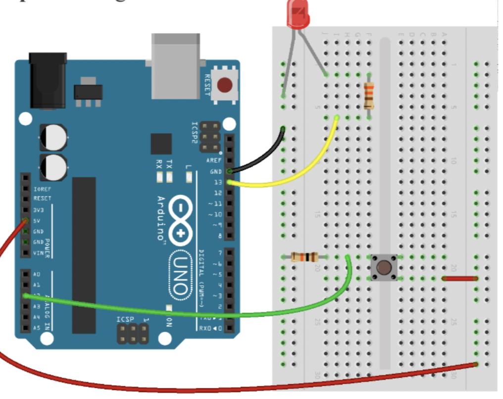
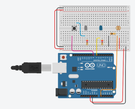
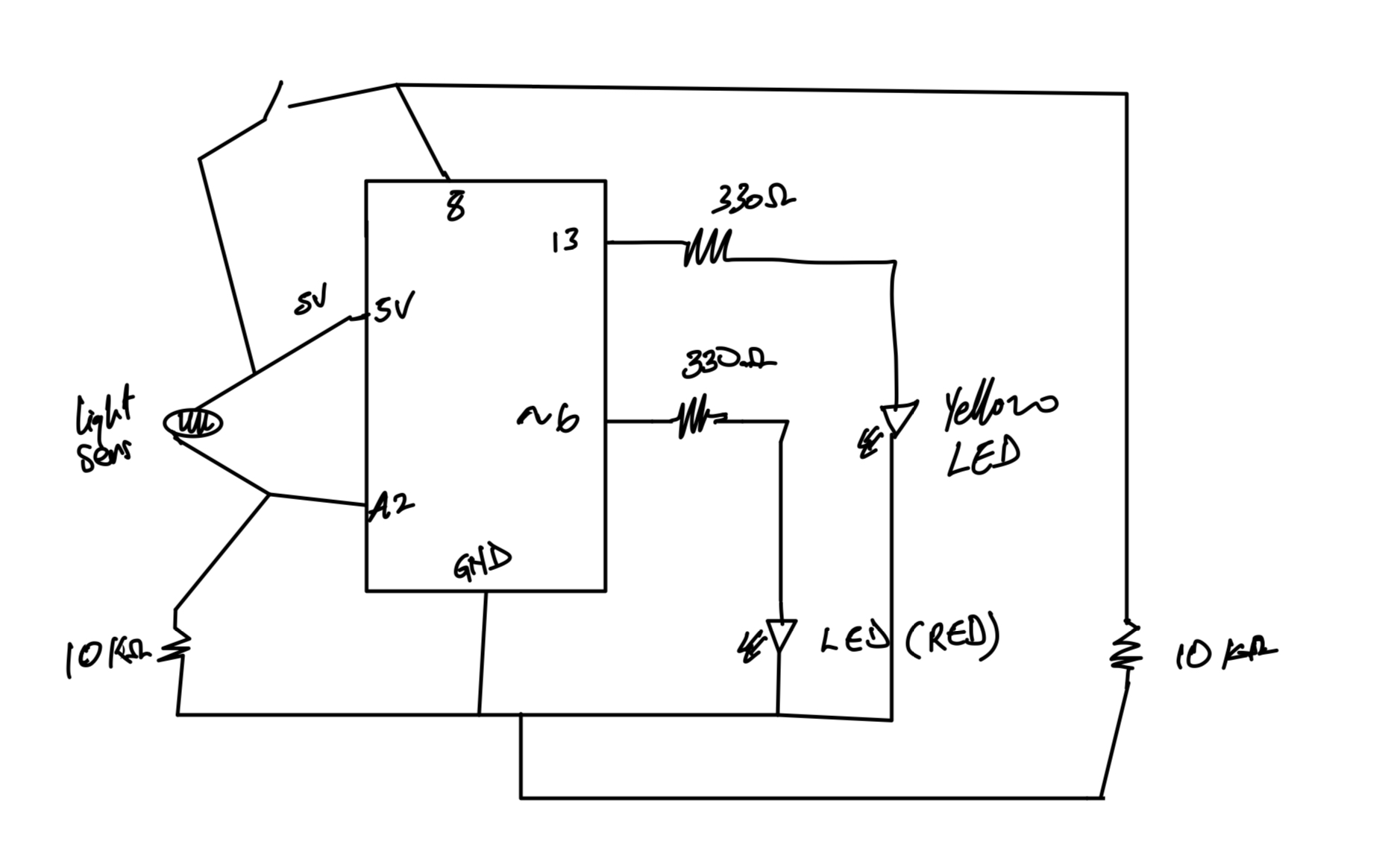
Circuit Diagram:
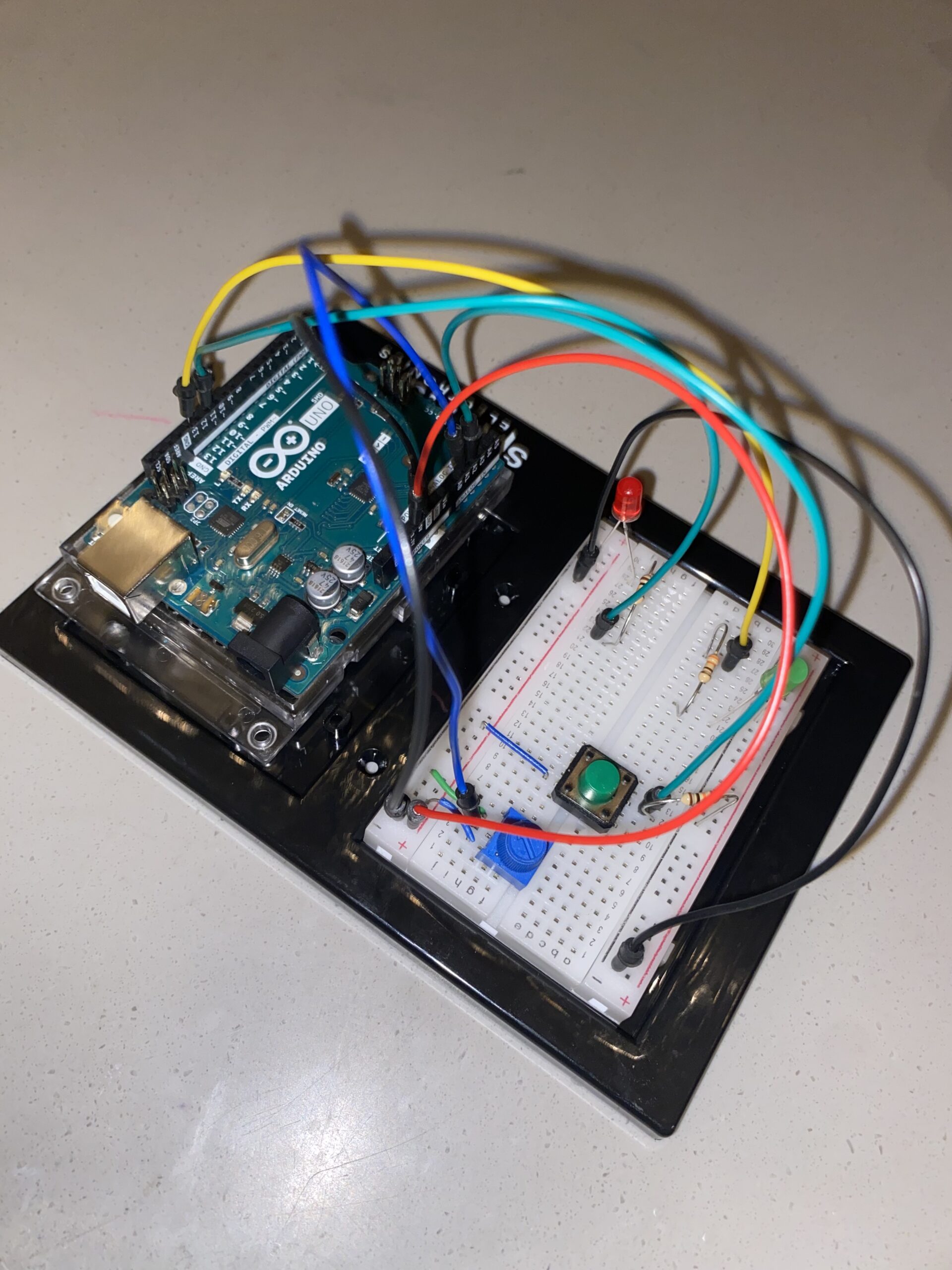
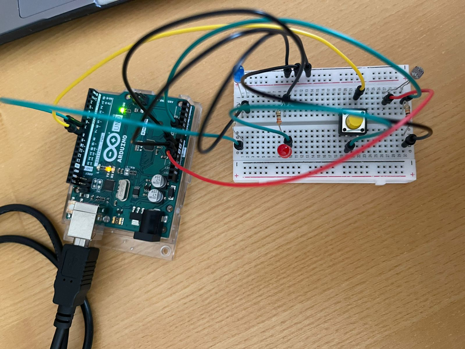
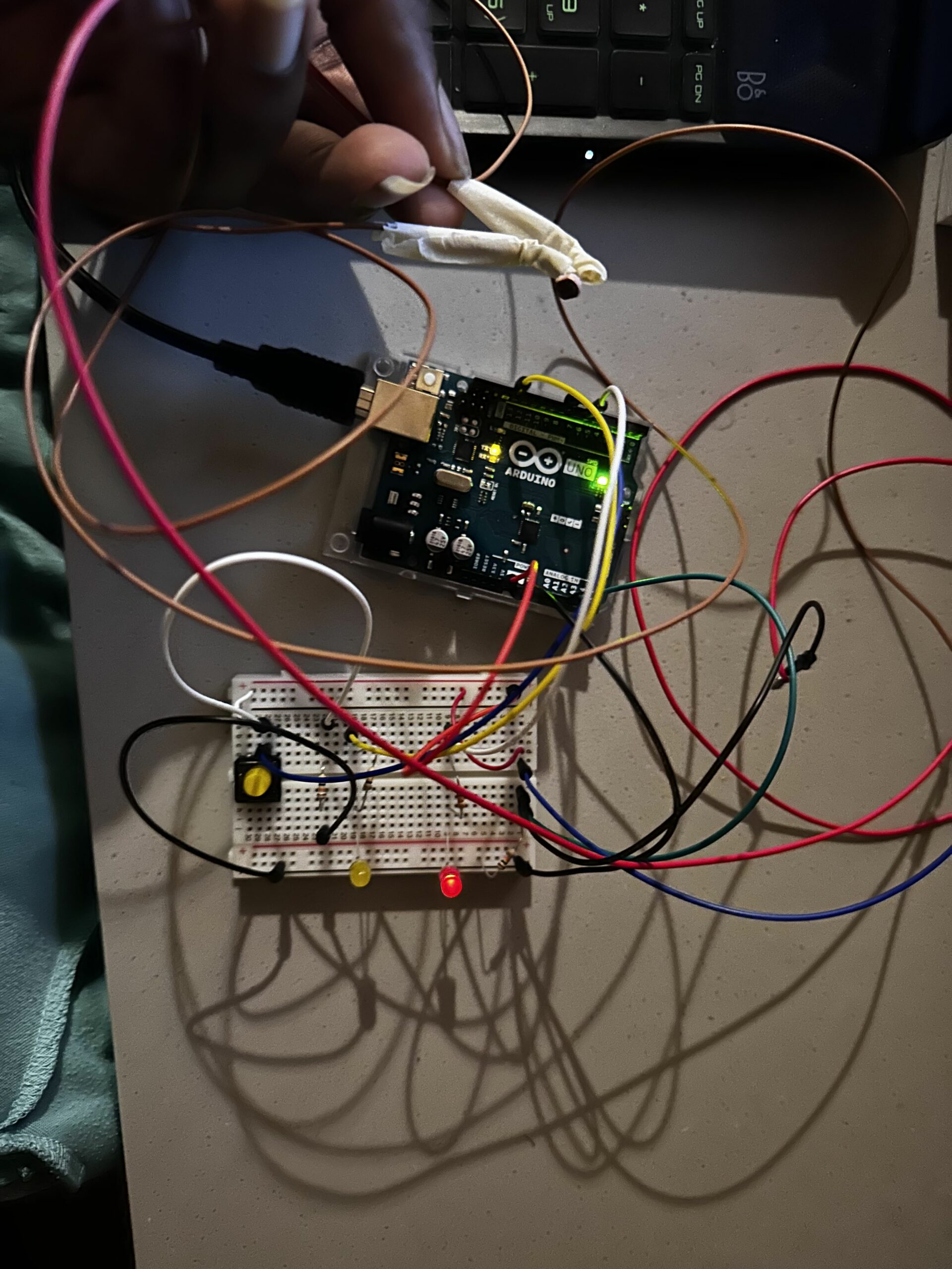
Set-Up Picture:
Video:
https://drive.google.com/drive/folders/17efBVjbUX72MkYQmuw92EqgqJVYxm1Oi?usp=sharing
Thank You!.