For my final project, I decided to make a running experience game with a timer. I had this idea so that people can exercise from home. A person puts the accelerometer on his/her leg clicks the button to start the game and presses it again to end it. I wanted to go with a simple design and a specific purpose for this project.
Highlight and Process:
Different placements of the Accelerometer and data results
This project did not go as smoothly as I expected it to be. I had to try multiple sensors to see which one fits my concept best. I tried a potentiometer, an XYZ-axis accelerometer, and a Gyroscope Accelerometer. I had to research a lot about them and see what can be done.
circuit accelerometerArcade Switch with LED
I decided to go on and use the ADXL335 Accelerometer. I read the documentation I found online for it. I have to say that figuring out the circuit was not the easiest thing either. I made the circuit maybe 5 times to get it right. I also decided to use the Arcade button with LED. I burned myself while soldering but I learned to be careful.
After figuring out the circuit and testing it with build-in examples, I moved on to designing the box and putting the accelerometer in a small container I made of two bottle caps. Cutting the box using the laser cutter was not smooth either as the laser cutter stopped working in the middle of cutting my box, and I had to redo it the next day. I made sure everything was in place and worked fine, then I moved to the code.
I started with the code, and I found an example of how to convert the data we get from the accelerometer to acceleration. This was my starting point. I refined the code a little bit to serve the purpose of my project. Then I added different elements like the button and the serial communication. However, when I did that the code stopped working. It took me two days to figure out the problem as highlighted in the pdf file attached.
// variables for the sensor x, y, z axis
const int xInput = A0;
const int yInput = A1;
const int zInput = A2;


// initialize minimum and maximum Raw Ranges for each axis
int RawMin = 0;
int RawMax = 1023;

// Take multiple samples to reduce noise we take the average of these
const int sampleSize = 10;

// for the arcade button state and its led
// pinmodes and pin #
int button = 8;
int LED = 4;
//state of the button
int buttonState = 0;
int lastButtonState = 0;

int LED_state = 0;

// Take samples and return the average from the accelemeter --
// readAxis function takes the 10 samples from analog to digital converter of
// an Arduino and delivers the average value.
int ReadAxis(int axisPin) {
  long reading = 0;
  analogRead(axisPin);
  delay(1);
  for (int i = 0; i < sampleSize; i++) {
    reading += analogRead(axisPin);
  }
  return reading / sampleSize;
}


void setup() {
  analogReference(EXTERNAL);
  Serial.begin(9600);

  // We'll use the builtin LED as a status output.
  // We can't use the serial monitor since the serial connection is
  // used to communicate to p5js and only one application on the computer
  // can use a serial port at once.
  pinMode(LED_BUILTIN, OUTPUT);
  pinMode(button, INPUT_PULLUP);
  pinMode(LED, OUTPUT);

  // start the handshake
  // while (Serial.available() <= 0) {
  //   digitalWrite(LED_BUILTIN, HIGH);  // on/blink while waiting for serial data
  //   Serial.println("0,0");            // send a starting message
  //   delay(300);                       // wait 1/3 second
  //   digitalWrite(LED_BUILTIN, LOW);
  //   delay(50);
  // }
}

void loop() {
  //Read raw values
  int xRaw = ReadAxis(xInput);
  int yRaw = ReadAxis(yInput);
  int zRaw = ReadAxis(zInput);

  // Convert raw values to 'milli-Gs"
  long xScaled = map(xRaw, RawMin, RawMax, -3000, 3000);
  long yScaled = map(yRaw, RawMin, RawMax, -3000, 3000);
  long zScaled = map(zRaw, RawMin, RawMax, -3000, 3000);

  // re-scale to fractional Gs 1/1000 0f g
  float xAccel = xScaled / 1000.0;
  float yAccel = yScaled / 1000.0;
  float zAccel = zScaled / 1000.0;

  // wait for data from p5 before doing something
  // while (Serial.available()) {
  digitalWrite(LED_BUILTIN, HIGH);  // led on while receiving data

  buttonState = digitalRead(button);
  if (button != lastButtonState && lastButtonState == 1) {

    // delay helps in false pushes
    delay(50);
    if (buttonState == LOW) {

      if (digitalRead(LED) == 1) {
        LED_state = 0;
        // turn LED off
        digitalWrite(LED, LED_state);
      } else {
        LED_state = 1;
        digitalWrite(LED, LED_state);  // Turn on LED
      }
    }
  }
  lastButtonState = buttonState;

  // if (Serial.read() == '\n') {
  // send to p5js
  // Serial.print(xRaw);
  // Serial.print(", ");
  // Serial.print(yRaw);
  // Serial.print(", ");
  // Serial.print(zRaw);
  // Serial.print(" :: ");
  Serial.print(xAccel);
  Serial.print(',');
  Serial.print(yAccel);
  Serial.print(',');
  Serial.print(zAccel);
  Serial.print(',');
  Serial.println(LED_state);


  delay(200);
  // }

  digitalWrite(LED_BUILTIN, LOW);
}
// }
When I figured out the Arduino side. I began designing the interface of the project. I had to create different levels so that the users could switch from the start of the experience to the end and back again. I decided to use the LED state to do that. Meaning that when the LED state is 1 the experience starts and when it Is zero it ends. In the States, I added what should happen. In the second state when the LED is 1, the timer starts and it starts looking through the sprite sheet at the rate of the Z-value multiplied by the time, which is linear speed. Unfortunately, I had to assume the physics to make it work and I am not sure how accurate it is. I have noticed that there is a little delay but I can’t figure out why. I think it is because P5js is a little slow.
P5js link ->https://editor.p5js.org/shn202/full/gOx6xjm6X
Reflection:
There is a lot more that can be done to this project. I will admit that I learned a lot implementing it and even though it is not as I expected it to be, I think with all the limitations and problems I faced it turned out to be good. In the future, I would like to make it more interactive with more preferences to it. I feel time was a challenge in this project and that if we had more time it would have turned out better.
Hello Kitty’s Adventure: The Car Dodging Challenge
I chose this project because for my midterm, I created an experience and for my final, I aimed to challenge myself by creating a game. Additionally, having received my license two months ago, it seemed like the perfect opportunity to develop a game involving cars.
This game, titled “Hello Kitty’s Adventure: The Car Dodging Challenge” lets you control a character resembling Hello Kitty, guiding her left and right to avoid colliding with cars. As you skillfully maneuver past every four cars, the game progresses to a new level, increasing in speed. Your score accumulates with each second you survive. This fun and engaging game is inspired by my long-time fondness for a character similar to Hello Kitty, which has been a favorite of mine since childhood.
prototype + Schematic (ultrasonic distance sensor, two LEDs) :
Exhibition
The Im showcase on Friday 15th was a blast! It was my first time being part of an exhibition and making a game, which turned out to be super fun. I really enjoyed it, especially chatting with people there. I got loads of compliments and comments on my project, like “Your project was the best,” “Did you make this? It’s amazing,” and “This game is addicting.” It feels great to see my hard work pay off. The course was fun and I’ve been proud of everything i achieved during the course. My friends showed up to support me, and seeing people smile while playing my game was the best part. Zion and Fausto even set the highest score at 77! Here are some pictures and videos from the showcase.
The structure of the project is crafted using recycled cardboard and cork that I found at home, a gesture to honor COP28 held in the UAE. Unfortunately, I couldn’t access the resources and equipment in the IM lab, as I wasn’t available during the weekend. Nevertheless, I am proud of how the prototype turned out. It has a homemade aesthetic that truly showcases the effort and creativity I invested in it. *Update: I drew road markings on the pink paper, to easily direct left right and middle*
The challenges I encountered primarily involved reacquainting myself with p5. After a break spent focusing on Arduino, I felt a bit out of touch with p5 and needed to catch up on some of its features. However, I am pleased with the final result, particularly the pink color scheme I chose, which I feel represents me well. Another significant challenge was working with Arduino. I frequently faced connectivity issues with my laptop, requiring multiple restarts whenever it failed to upload. Additionally, getting the ultrasonic sensor to accurately measure distances was tricky, but after consulting numerous videos, I managed to overcome this obstacle. Despite these challenges, I am proud of what I accomplished. *Update: the issue of the arduino lagging was fixed by Muhammad Khan who was kind enough to fix the code for me, now Id say it works perfectly with no lag*
let car, helloKitty; // images for car and Hello Kitty character
let phase = "startScreen"; // current phase of the game: startScreen, game, endScreen, instructions
let speedCount = 0; // counter to track speed and timing of game elements
let speed = 1; // initial speed of moving cars
let cars = []; // array to hold car objects for collision detection and rendering
let gameOverImg; // image to be displayed when the game is over
let arduinoData = 0; // data received from Arduino for control
let useArduinoControl = true; // flag to enable or disable Arduino control
let rVal = 0;


// -------------------------------------------------------------------------------------

// preloads game assets (images, fonts, sounds)
// before starting the game

function preload() {
  car = loadImage("pink1.png");
  helloKitty = loadImage("hellokitty.png");
  StartUp = loadImage("workpls.png")
  customfontkitty = loadFont('kittyfont2.ttf');
  customfontsan = loadFont('san.ttf');
  gameOverSound = loadSound("ouch.mp3");
  introSound = loadSound("introsong.mp3");
  leftBorder = loadImage("leftBorder.png");
  rightBorder = loadImage("rightBorder.png");
  instructionImg = loadImage("instructions8.png");
  }

// ----------------------------------------------------------------------------

// sets up the initial state of the game canvas and variables

function setup() {
  createCanvas(400, 600);

  rectMode(CENTER);
  imageMode(CENTER);

  kittyX = 115; // initial X position for Hello Kitty
  kittyY = 550; // initial Y position for Hello Kitty
  score = 0; // initialize score
  level = 1; // initialize game level
}


// ----------------------------------------------------------------------------


// The main game loop, executed continuously to render the game


function draw() {

  background(50, 140, 80); // set the background color

  if (phase == "game") {
    fill(255,204,220);
    noStroke();

    // fisplay the left and right border images on the screen
    image(leftBorder, 20,height/2,leftBorder.width*0.55,leftBorder.height*0.55);
    image(rightBorder, 380,height/2,rightBorder.width*0.55,rightBorder.height*0.55);

    // draw the central playing area
    rect(width / 2, height / 2, 320, height);
    fill(255);

    // creates the road markings
    for (let i = 0; i < 4; i++) {
    for (let j = -1; j < 10; j++) {
    rect(75 + i * 80, (speedCount % 60) + 30 + 60 * j, 6, 50);
      }
    }

   // increment speedCount to control the moving speed of road markings
    speedCount += speed;

   // arduino Control: Move Hello Kitty based on Arduino input
      if (useArduinoControl && arduinoData !== null) {

      if (arduinoData < 10) { // move left
           kittyX = 115;
        } else if (arduinoData >= 10 && arduinoData < 20) {  // Move center
           kittyX = 195;
        } else if (arduinoData >= 20) {  // Move right
           kittyX = 275;
        }
     }

    // returns the hello kitty to current position

    image(helloKitty, kittyX, kittyY, 70, 100);


    // on every 50th speed count a car will come down
    if (speedCount % 200 == 0) {
        cars.push({
            x: random([115, 115 + 80, 115 + 160]), // Random lane
            y: -40, // Start above the screen
        });
    }

    // move each car
    for (let i = 0; i < cars.length; i++) {
        image(car, cars[i].x, cars[i].y, 70, 100);


    // checks for collision with Hello Kitty
      if (dist(cars[i].x, cars[i].y, kittyX, kittyY) < 60) {
        phase = "gameOver";
        gameOverImg = get(0, 0, width, height);
        gameOverSound.play();
        introSound.stop();
    }

    // update car position
      cars[i].y += speed * 2;
    }


    // display score and level
    textSize(16);
    stroke(255);
    strokeWeight(2);
    fill("#9B858D");
    text("SCORE : " + score, 20, 30);
    text("LEVEL : " + level, 320, 30);

    // increment score over time
    if (frameCount % 60 == 0) {
      score++;
    }

    // increase speed and level after certain intervals
    if (speedCount % 1000 == 0) {
      speed += 1;
      level += 1;
    }
  }

// ----------------------------------------------------------------------------

 // display the game over screen and show score and level reached

  if (phase == "gameOver") {
    image(gameOverImg,width/2,height/2);
    textSize(16);
    strokeWeight(2);
    stroke(0);
    fill(0, 100);
    rect(width / 2, height / 2, 240, 150);
    fill(255);
    stroke(255);
    strokeWeight(1);
    text("Level " + level + " Reached", 145, 250);
    textSize(14);
    text("   You Scored " + score, 145, 360);
    text(" press Enter to Restart", 135, 330);
    fill(255);
    textSize(32);
    text(" GAME OVER", 105, 300);
  }

  // checks if the current game phase is the start screen
  if (phase == "startScreen") {
    if(!introSound.isPlaying()){
      introSound.loop();
    }


// ----------------------------------------------------------------------------

// start up image and text

    background("#9B858D");
    fill(255,192,203,0.60);
    image(StartUp, width/2, height/2, StartUp.width*0.7, StartUp.height*0.7);
    rect(width / 2, height / 2, 380, 580);
    stroke(255);

    fill(255);
    strokeWeight(6);
    stroke(255, 192, 230);
    fill(255, 105, 180);
    textFont(customfontkitty);
    textSize(86);
    text("hello kitty", 20, 120);

    fill(255, 105, 180)
    textSize(60);
    strokeWeight(2)
    stroke(255);
    textFont(customfontkitty);
    text("adventure", 70, 175);

    fill(171,209,158);
    rect(width / 2, 480, 200, 80, 50);
    fill(255);
    textFont(customfontkitty);
    text("start", 140, 500);

    stroke(171,209,158);
    strokeWeight(2)
    fill(255);
    textSize(28);
    text("   Press Enter for Instructions",10,570)


    // check if the mouse position is within a specified rectangular area
    if (
      mouseX > width / 2 - 100 &&
      mouseX < width / 2 + 100 &&
      mouseY > 460 &&
      mouseY < 540
    ) {

    // If the mouse is within the specified area it changes to game phase
    if (mouseIsPressed) {
      mouseIsPressed = false;
      phase = "game";
      }
    }
  }

// -------------------------------------------------------------------------------------

// intruction page

  if (phase == "instruction"){

    image(instructionImg,200,300,400,600); // display the instruction image

    strokeWeight(2);
    stroke(0);
    textSize(60);
    textFont(customfontkitty);
    fill(0);
    text("How To Play",40,120);
    textFont();

    textFont(customfontsan);
    strokeWeight(1);
    textSize(20);
    text("      \n     1) move your hands left   \n          and right to move \n                  hello kitty  \n       2) try to avoid the cars   \n                3) BE SAFE!",60,330);
    textSize(20);
    text("      press enter to go back \n                 and start! ",70,500)
  }
}

// function to handle keyboard inputs


function keyPressed() {

  // game control using arrow keys during the 'game' phase
  if (phase == "game") {
    switch (key) {
      case "ArrowLeft":
        if (kittyX > 115) {
          kittyX -= 80;
        }
        break;
      case "ArrowRight":
        if (kittyX < 260) {
          kittyX += 80;
        }
        break;
      default:
        break;
    }
  }

  // restart the game when 'Enter' is pressed in the 'gameOver' phase
  if (phase == "gameOver") {
    if (key == "Enter") {
      score = 0;
      level = 1;
      speedCount = 0;
      speed = 0;
      cars = [];
      phase = "startScreen";
      kittyX = 75;
      kittyY = 550;
      key="";
    }
  }

  // handle key presses for navigating between instruction and start screen
  if(phase=="instruction"){

    if(key== "Enter"){
      phase = "startScreen";
      key="";
    }
  }

  if(phase=="startScreen"){
    if(key== "Enter"){
      phase = "instruction";
      key="";
    }
  }

  //  setup serial communication when spacebar is pressed
  if (key == " ")
  {
    setUpSerial();
  }
}


// -------------------------------------------------------------------------------------

// arduino

function mouseIsPressed()
{
  readSerial();
}

// This function will be called by the web-serial library
// with each new line of data. The serial library reads
// the data until the newline and then gives it to us through
// this callback function

let lastDataReceivedTime = 0;

function readSerial(data) {
  if (data != null) {
    arduinoData = parseInt(data);
    lastDataReceivedTime = millis();
    useArduinoControl = true;
  } else if (millis() - lastDataReceivedTime > 2000) { // 2 seconds timeout
    useArduinoControl = false;
  }


 let sendToArduino = 0;
  switch (phase) {
    case 'game':
      sendToArduino = 1;
      break;
    case 'instruction':
    case 'startScreen':
      sendToArduino = 2;
      break;
    case 'gameOver':
      sendToArduino = 3;
      break;
  }
  writeSerial(sendToArduino + "\n");
}
const int trigPin = 9;  // Pin number for the ultrasonic sensor's trigger pin
const int echoPin = 10; // Pin number for the ultrasonic sensor's echo pin
const int ledgreen = 4; // Pin number for the green LED
const int ledred = 7;   // Pin number for the red LED
long duration;          // Variable to store the duration of the echo pulse
float distance;         // Variable to store the calculated distance

void setup()
{
  pinMode(trigPin, OUTPUT);  // Set the trigPin as an output
  pinMode(echoPin, INPUT);   // Set the echoPin as an input
  Serial.begin(9600);        // Start serial communication at 9600
  pinMode(ledgreen, OUTPUT); // Set the green LED pin as an output
  pinMode(ledred, OUTPUT);   // Set the red LED pin as an output
}

unsigned long ultrasonic_clock = 0;
unsigned long led_clock = 0;
float sum = 0;
int iterator = 0;

void loop()
{

  if (millis() - ultrasonic_clock >= 5) // Take reading every 5 ms
  {
    ultrasonic_clock = millis();

    digitalWrite(trigPin, LOW); // Clear the trigPin
    delayMicroseconds(2);
    digitalWrite(trigPin, HIGH); // Set the trigPin to HIGH state for 10 microseconds
    delayMicroseconds(10);
    digitalWrite(trigPin, LOW); // Set the trigPin to LOW state

    duration = pulseIn(echoPin, HIGH); // Read the echoPin, returns the sound wave travel time in microseconds
    distance = duration * 0.034 / 2;   // Calculate the distance

    sum += distance;
    iterator++;

    if (iterator == 5) // Average the last 5 readings
    {
      Serial.println(int(sum / 5));
      iterator = 0;
      sum = 0;
    }
  }

  if (millis() - led_clock >= 10) // Take reading every 10 ms
   {
  led_clock = millis(); //record the time this code ran

  // reading brightness level from serial
  //   int brightness = Serial.parseInt();
  if(Serial.read() == '\n'){

  // controlling LED based on brightness level
      if(brightness == 1){
         digitalWrite(ledgreen, HIGH);
        digitalWrite(ledred, LOW);
       }
     else if(brightness == 2){
        digitalWrite(ledgreen, LOW);
        digitalWrite(ledred, LOW);
       }
      else if(brightness == 3){
         digitalWrite(ledred, HIGH);
         digitalWrite(ledgreen, LOW);
       }
     }
    }
}
Improvements
For future improvements, I aim to rely less on external help, as I did encounter significant struggles. I plan to apply the skills acquired from tool training to craft an even better prototype using materials like wood and acrylic. Additionally, I’ll consider utilizing various components to enhance the game or possibly explore a different direction and different sensors for this project. Starting earlier will also be a priority, allowing ample time for revisions, enhancements, and potentially incorporating more features. Overall, I am proud of my work and have gained a deep appreciation for the effort, thought, and creativity required by those who do this professionally. Creating a project that not only reflects my aesthetic but also functions effectively has been a rewarding experience. I am extremely pleased with the outcome and feel a sense of accomplishment for what I have achieved.
IMG_7438For my final project, I had to last minute change the concept since my midi controller idea fell through and proved to be unfit for this assignment. My project now is a musical map that lets users play music from different regions of the world. I initially wanted to create a map of the globe but decided to consolidate my map into one continent. The continent I chose was South America (SA). South America resonated with me the most because of my love of Latin American music! I initially was going to take an image of the map from off of the internet but decided to design my own map of SA. This was designed in Adobe Illustrator.
I picked a total of 13 songs all from different parts of SA:
Brazil: Dindi – Sylvia Telles
Venezuela: Mi Corazon – Los Melodicos
Colombia: Tobaco y Ron – Rodolfo y su typica ra7
Ecuador: Escribeme – Tierra Canela
Suriname: Moi Misi – Sabokoe
Guyana: Catch me Lova – JMC
French Guiana: Kraze Dj Action X Jaydieff
Peru: Peru de Valses: Y se llama Peru – Oscar Avilles
Users simply can move the joystick, which acts as a cursor on the screen and press on the squares in the p5 sketch to trigger a unique sound file from each country.
Aesthetic Design:
I made my box out of cardboard and painted on several separate sheets of paper a similar color scheme to my digital design of the map. I then glued those pieces of paper onto the box!
I initially had quite a few issues in p5 trying to upload the song files. I realized that it was because I placed all the songs in a folder and P5 couldn’t find the path to that folder. I also had issues with organizing the square buttons on the screen, as well as cuing and pausing the music in combination with the joystick!
Improvements:
I would really like to make my p5 sketch a bit more elaborate and maybe add some sort of extra LED aspect to my arduino to make things a bit more exciting!
My project concept is one I came to fall in love with. I always liked the idea of taking pictures and so being able to create an interactive environment, where I am able to solve a puzzle using a picture I just took, I think is very fun. This I think is a metaphor for just how challenging but fun this class was. The puzzle could represent some of the challenges I faced throughout the class and building the puzzle represents the way in which my skills developed over the course of the 14 weeks. At the end when you look at the finished puzzle and feel proud of yourself for solving, represents how happy and proud I am of myself, not only to have finished the class, but having done so with new skills and I guess a love for physical computing. I feel like a genius, which is exactly what my LCD screen says when I complete the puzzle.
Schematic and Modelling:
Images of project:
User Testing videos:
How does the implementation work?
The project’s core idea is straightforward: manipulate the puzzle pieces using the joystick and follow on-screen instructions by pressing the buttons accordingly. The inspiration behind this setup actually came from the PS5 controller. I was dead set on incorporating a joystick into the design, and that sparked the whole concept.
Description of interaction design:
The design is meant to be user-friendly. I aimed for simplicity, assuming everyone knows the basics of a joystick. The on-screen instructions should guide players smoothly through the game. It’s a balance—simple enough for anyone to dive in yet not overly basic to bore them. That’s where the difficulty levels come in. I’ve got three, but I’ve only tested two myself, only managing to crack the first level. Give it a shot and see how far you can go!
Description of Arduino code + code snippets
The Arduino sketch I’ve got sets up a cool interface using buttons and a joystick to handle an LCD display and communicate using serial communication. First off, it gets things going by setting up pins for the buttons and joystick, along with initializing a LiquidCrystal display. The setup() function takes care of configuring serial communication, initializing pins, and prepping the LCD screen. The loop() function takes care of button presses and joystick moves. And when it detects these actions, it sends messages through serial communication. Each action—like a mouse click, difficulty level selection, joystick move, or even a command to snap a picture—is translated into a specific message. This sketch is a great listener too. It keeps an ear out for incoming messages through the serial port. When it gets specific ones like ‘TIMER:’, ‘MOVES:’, or ‘SOLVED’, it updates the LCD screen accordingly. So, you’ll see things like timer values ticking away, move counts racking up, and a sweet congratulatory message popping up when you crack that puzzle.
#include <LiquidCrystal.h>

const int XbuttonPin = 2;
const int SbuttonPin = 3;
const int TbuttonPin = 4;
const int CbuttonPin = 5;
const int joystickXPin = A0; // Analog pin for joystick X-axis
const int joystickYPin = A1; // Analog pin for joystick Y-axis
const int threshold = 50; // Threshold for joystick sensitivity
//bool isDifficulty = false;

LiquidCrystal lcd(6, 12, 11, 10, 9, 8);

void setup() {
  Serial.begin(9600);
  pinMode(XbuttonPin, INPUT_PULLUP);
  pinMode(SbuttonPin, INPUT_PULLUP);
  pinMode(TbuttonPin, INPUT_PULLUP);
  pinMode(CbuttonPin, INPUT_PULLUP);

  lcd.begin(16, 2);
  lcd.clear();
}

void loop() {
  if (digitalRead(XbuttonPin) == LOW) {
    Serial.println("MOUSE_CLICK");
    delay(1000); // Debounce delay
  }

  if (digitalRead(SbuttonPin) == LOW) {
    Serial.println('2');
    delay(100); // Debounce delay
  }

  if (digitalRead(TbuttonPin) == LOW) {
    Serial.println('1');
    delay(1000); // Debounce delay
  }

  if (digitalRead(CbuttonPin) == LOW) {
    Serial.println('3');
    delay(100); // Debounce delay
  }

  if (digitalRead(TbuttonPin) == LOW) {
    Serial.println('C');
    delay(100); // Debounce delay
  }

  int xVal = analogRead(joystickXPin); // Read X-axis value
  int yVal = analogRead(joystickYPin); // Read Y-axis value

  if (xVal < 512 - threshold) {
    Serial.println("LEFT");
    delay(500); // Debounce delay
  } else if (xVal > 512 + threshold) {
    Serial.println("RIGHT");
    delay(500); // Debounce delay
  }

  if (yVal < 512 - threshold) {
    Serial.println("DOWN");
    delay(500); // Debounce delay
  } else if (yVal > 512 + threshold) {
    Serial.println("UP");
    delay(500); // Debounce delay
  }
  if (Serial.available() > 0) {
    String message = Serial.readStringUntil('\n');

    if (message.startsWith("TIMER:")) {
      lcd.setCursor(0, 0);
      lcd.print(message.substring(6)); // Print the timer message
    } else if (message.startsWith("MOVES:")) {
      lcd.setCursor(0, 1);
      lcd.print("Moves: " + message.substring(6)); // Print the move counter message
    } else if (message == "SOLVED") {
      lcd.clear();
      lcd.setCursor(0, 0);
      lcd.print("You are a GENIUS!!!");
      delay(5000); // Display "Puzzle Solved!" for 2 seconds
      lcd.clear();
    }
  }
}
Description of p5.js code + code snippets + embedded sketch
My p5.js puzzle game lets you interact with images, customizable with varying difficulty levels. It progresses through welcome, instructions, and gameplay phases. The Puzzle class manages the game mechanics—moves, shuffling tiles, checking progress, and joystick input. The draw() function orchestrates screens, responding to commands from sources like Arduino. Background music sets the tone for welcome and instructions, fading during gameplay focus. The setup() function initializes the canvas, video feed, and initial puzzle grid, making it the core of this interactive experience.
function captureAndSetupPuzzle(video) {
  if (video) {
    source = video.get();
    source.loadPixels(); // Ensure pixels are loaded
 if (source.width > 0 && source.height > 0) {
    // Resize the source image to fit the canvas
    source.resize(width, height);
    video.hide();

    w = Math.floor(width / cols);
    h = Math.floor(height / rows);

    for (let i = 0; i < cols; i++) {
      for (let j = 0; j < rows; j++) {
        let x = i * w;
        let y = j * h;
        let img = source.get(x, y, w, h); // Get a portion of the image for each tile

        if (i === cols - 1 && j === rows - 1) {
          board.push(-1);
          puzzle.tiles.push(new Tile(-1, img));
        } else {
          let index = i + j * cols;
          board.push(index);
          puzzle.tiles.push(new Tile(index, img));
        }
      }
    }

    puzzle.board = board.slice();
    puzzle.simpleShuffle(puzzle.board);

    currentScreen = 'game';
    puzzle.startTimer();
  } else {
    console.error("Error loading the video source");
    }
  }
}
function joystick(puzzle, direction) {
  let xOffset = (width - puzzle.w * puzzle.cols) / 1.3;
  let yOffset = (height - puzzle.h * puzzle.rows) / 2.5;

  // Calculate the tile indices based on joystick direction
  let i = -1,
    j = -1;
  let blank = puzzle.findBlank();
  let blankCol = blank % puzzle.cols;
  let blankRow = Math.floor(blank / puzzle.rows);

  switch (direction) {
    case 'LEFT':
      i = blankCol + 1;
      j = blankRow;
      moveSound.play();
      break;

    case 'RIGHT':
      i = blankCol - 1;
      j = blankRow;
      moveSound.play();
      break;

    case 'UP':
      i = blankCol;
      j = blankRow + 1;
      moveSound.play();
      break;

    case 'DOWN':
      i = blankCol;
      j = blankRow - 1;
      moveSound.play();
      break;

    default:
      // Handle other cases or unknown commands
      break;
  }

  if (i >= 0 && i < puzzle.cols && j >= 0 && j < puzzle.rows) {
    puzzle.move(i, j, puzzle.board);
  }
  writeSerial("MOVES:" + puzzle.getMoves() + "\n");
 // puzzle.updateTimer(); // Update the timer
 // puzzle.displayTimer(); // Display the timer
}
Description of communication between Arduino and p5.js
In my project, the Arduino and p5.js are like buddies chatting through a USB connection using serial communication. The Arduino sends messages over to p5.js, which eagerly listens and understands what’s being said. Depending on these messages, p5.js swings into action—triggers different functions, or tweaks how the whole thing behaves. It’s like they’re choreographing a dance together! This connection allows the tangible aspects of my project—like button pushes or sensor readings from the Arduino—affect what happens on the digital playground of the p5.js sketch. It’s a smooth back-and-forth: the Arduino talks to p5.js, guiding its moves, while p5.js keeps the Arduino in the loop about how the game’s going—sending updates on moves made and puzzles solved. They’ve got this teamwork thing down, with the Arduino shaking things up in the digital world and p5.js keeping it informed about what’s happening in the game.
What are some aspects of the project that you’re particularly proud of?
One thing I’m really excited about is achieving two-way communication in my project. It was a bit of a hurdle because I’ve always been more comfortable with software like p5.js, which made tasks like controlling mouse clicks and key presses with Arduino a breeze. But the real challenge came when I needed to send information back from p5.js to the Arduino IDE. Figuring out how to establish that connection was a bit tricky, but once I got it working, it felt like a big win.
Another part that I’m super proud of is the capture process. Initially, I had the picture saved and then converted it into the grid. However, I realized this meant that everyone’s picture would end up stored on my laptop, and I wasn’t keen on that idea. So, I reworked the code to immediately convert the picture as soon as it’s taken. I love this feature because it ensures privacy by not saving anyone’s picture on my device, and it’s more immediate and seamless for the users.
One of the toughest parts I tackled was turning the picture into a grid and getting those tiles to shift around. The real challenge here wasn’t just making the picture the puzzle, but doing it on the spot—taking a photo and instantly turning it into a puzzle. It felt like a puzzle itself! For a while, I hit a roadblock. I could snap the picture, form the tiles, but they just wouldn’t budge. Turned out, they weren’t connecting to my puzzle class properly. It was like they were stuck in place. To fix this, I had to dive into the puzzle class and really fine-tune how the capturing worked. It was trial and error, a lot of experimenting. Then, I stumbled upon this function called video() in p5.js, and that was a game-changer. It helped me get things back on track and finally, my project started to click.
Future Work:
I’ve been thinking about how to take this project to the next level and turn it into more of a game. For me, this whole thing has been a way to relax and unwind, not really about competing. But I think adding a competitive element could make it way more interesting. I’ve been considering the idea of making it multiplayer, so that more than one player can get involved in the game. Imagine friends coming together, enjoying some puzzling challenges, and maybe even a bit of friendly competition. It could be a great way for them to hang out and have a good time. By making these changes, I believe it’ll become a fun escape for folks who enjoy puzzles or just want to kick back and have some light-hearted rivalry.
For my final project, I was initially inspired to create a fortune teller by my favorite book series, The Raven Cycle, in which the main character is from a family of psychics. The interface went through many iterations to become what it is now. First, I thought it would be a telephone interface, in which the user would “call” different numbers to get different predictions. Then, I thought I would make a “Magic 8 Ball” type object with a digital screen to display the various predictions. Finally, I settled on an entirely non digital display because I wanted the “whimsical” feel of hand painted cardboard. A conversation with Professor Shiloh further encouraged me to go with this option, as when I shared my idea for having “wheels” that would rotate to display the predictions, he suggested that the predictions could be split up into sentence beginnings and endings, which would allow for many more combinations.
Thus, my final design consisted of two wheels attached to servo motors. When the user presses a button, the servos would choose two random angles to rotate to from an array of predetermined angles. The angle of rotation would then determine which sentence beginning and ending showed through the display slot. With the help of Chat GPT, I generated 6 sentence beginnings and endings that can all combine together to form 36 coherent predictions regarding relationships, the future, and self improvement.
Interaction Design & User Testing
The interaction between the user and the fortune teller is quite straightforward — the user pushes a button and receives a fortune. During my user-testing, I was pleasantly surprised to see that people enjoyed receiving different fortunes, and would press the button many times to see new fortunes. They also related the fortunes to their own lives, which reminded me of why humans enjoy things like astrology and fortune cookies. Even if we do not actually believe in their accuracy, it is still fun to apply these vague predictions to our current situations, and I think this is what motivated people to have a sustained interaction with my project. Furthermore, I think the fact that you can see the wheels spinning lends intrigue to the interaction. I think the simplicity of the interaction turned out to be its strength, as people quickly figured out what to do and did not need any explanation from me.
My code consisted of three main mechanisms, one for detecting button state, one for choosing a random angle for each of the servo motors, and one for moving the servos smoothly to the chosen angle. One of the most difficult part of this assignment for me was understanding the logic behind each of these mechanisms, as I had never used state detection in any of my previous projects.
1. Button State: If the current button state is different than the previous button state AND it is high, meaning that the user has pressed the button, then the subsequent actions of choosing a random angle and moving the servos will take place.
2. Angle Selection: A random angle is chosen from an array of angles. The code will keep searching for a new angle until it is different from the previous angle, thus preventing an occurrence of the same 2 angles in a row. This is repeated for both servos.
3. Moving Servo: The for loop is for detecting if the previous angle is larger than or smaller than the current angle, and for smoothly incrementing the servo degree by degreee (either adding 1 or subtracting 1) to reach that angle. I did this after I found that not using the for loop resulted in extremely jerky movements.
Full code:
// Include Servo library
#include <Servo.h>

// Initialize servo object
Servo servoL;  // left servo
Servo servoR;  // right servo

// Variables for pins
const int servoPinL = 11;
const int servoPinR = 9;
const int buttonPin = 7;

// Set last button state to LOW
int lastButtonState = HIGH;

// Set last angle index to 0, aka the first angle in the array
int lastAngleIndexL = 0;
int newAngleIndexL;

int lastAngleIndexR = 0;
int newAngleIndexR;


// Array of angles for servo motor to choose from
int angles[] = { 10, 35, 63, 94, 123, 159 };

// 10, 35, 63, 94, 123, 159
// Calculate size of angles[] array, needed for random()
int sizeAngles = sizeof(angles) / sizeof(angles[0]);

void setup() {
  Serial.begin(9600);

  servoL.attach(servoPinL);
  servoR.attach(servoPinR);
  pinMode(buttonPin, INPUT_PULLUP);

  // Initialize servos at the first angle in angles[] array
  servoL.write(angles[lastAngleIndexL]);
  servoR.write(angles[lastAngleIndexR]);

  // Initialize random number generator
  randomSeed(analogRead(0));
}

void loop() {
  int currentButtonState = digitalRead(buttonPin);
  delay(15);

  if (lastButtonState != currentButtonState) {
    if (currentButtonState == LOW) {

      //// LEFT SERVO ////
      do {
        // generate a new random angle index
        newAngleIndexL = random(sizeAngles);
        // keep looking for a new random angle until it is different from the last
      } while (newAngleIndexL == lastAngleIndexL);

      // decide which way to turn
      if (angles[lastAngleIndexL] < angles[newAngleIndexL]) {
        for (int pos = angles[lastAngleIndexL]; pos < angles[newAngleIndexL]; pos++)
          servoL.write(pos);
        delay(100);
      } else {
        // go in other direction, pos--
        for (int pos = angles[lastAngleIndexL]; pos > angles[newAngleIndexL]; pos--)
          servoL.write(pos);
        delay(100);
      }

      Serial.print("Left Servo Angle: ");
      Serial.println(angles[newAngleIndexL]);

      //update the lastAngleIndex to show that we are now here
      lastAngleIndexL = newAngleIndexL;

      //// RIGHT SERVO ////
      do {
        // generate a new random angle index
        newAngleIndexR = random(sizeAngles);
        // keep looking for a new random angle until it is different from the last
      } while (newAngleIndexR == lastAngleIndexR);

      // decide which way to turn
      if (angles[lastAngleIndexR] < angles[newAngleIndexR]) {
        for (int pos = angles[lastAngleIndexR]; pos < angles[newAngleIndexR]; pos++)
          servoR.write(pos);
        delay(100);
      } else {
        // go in other direction, pos--
        for (int pos = angles[lastAngleIndexR]; pos > angles[newAngleIndexR]; pos--)
          servoR.write(pos);
        delay(100);
      }

      Serial.print("Right Servo Angle: ");
      Serial.println(angles[newAngleIndexR]);

      //update the lastAngleIndex to show that we are now here
      lastAngleIndexR = newAngleIndexR;
    }

    // update the button state
    lastButtonState = currentButtonState;
  }
}
I did not have any p5.js code or serial communication as I was granted an exception to do my whole project in Arduino.
Parts I am proud of:
The most frustrating part of my project was the interaction between the Arduino code and the physical cardboard construction, especially since the angles of rotation were integral to the whole concept working. First, I tried to draw the angles on the cardboard and try to write the code so that the angles I determined would cause the predictions to show through. This proved unsatisfactory and I had to reduce the number of wedges from 10 to 6, and eventually I wrote another program using the Knob servo example so that I could decide the angles based on which area showed through the display slot as I turned the knob, instead of deciding the angles first.
Additionally, the servo motors were very jittery and unstable at times, which made testing my concept an arduous process, as I had to continually disassemble both the cardboard slot and the motors to achieve an optimal setup. Thus, I am most proud of overcoming all these difficulties along the road, and making a (relatively) stable physical product with a form that serves its function well. I am also happy with the cardboard construction techniques I used, such as supporting my structure with triangle wedges:
Future Improvement:
If I were to do this project again, I would precisely measure and calculate everything before construction so I could have space for more predictions like I originally planned. Also, currently the wheels will turn erratically or the servo motors will vibrate at random times, and I still do not know why. An area for future improvement would be to eradicate these bugs, although they could be interpreted as divine psychic interference :).
I aimed to delve into recreating a retro game named “Feed Flynn,” blending the Catcher and spaceship Tyrian games into one fun experience. Inspired by the saying “don’t eat the book” and my deep fondness for food, I wanted to craft a game celebrating my love for food—an arcade-style creation I call “Feed Flynn.”
You get points for Feeding Flynn donuts +10,
Burgers ( full Meal ) + 20
Books -3 (why would you even feed Flynn Books ;( )
Flynn also has the ability to shoot bullets to eliminate the books. It’s a 35-second challenge to compete for the highest score, a way to test your skills and challenge your friends for the top spot!
The game adopts a retro vibe with:
A glitchy character sprite
Pixelated character design
Incorporation of music and sound effects
Include some pictures / video of your project interaction
this is how my project hardware is looking ( retro arcade)
I decided to have my single line of instruction Do NOT eat the books on the box; Condensing complex rules into concise, clear instructions often enhances comprehension and user engagement
How does the implementation work?
Description of interaction design
Interaction design involves creating the interface between a user and a system, aiming to optimize the user’s experience. In the context of “Feed Flynn,” the game utilizes four arcade buttons to facilitate the player’s interaction:
Start/Restart Button: This button initiates the game or restarts it once it’s over. It serves as the gateway to engage with the game, allowing the player to enter the gaming experience.
Right/Left Buttons: These two buttons enable the movement of Flynn, the character, within the game. They provide directional control, allowing Flynn to navigate right or left within the gaming environment, dodging falling objects or positioning to catch desired items.
Bullet Firing Button: This button empowers Flynn to shoot bullets in the game. By pressing this button, players can eliminate books, preventing them from being consumed by Flynn and avoiding point deductions. It adds an element of strategy and skill to the gameplay, requiring players to decide when to fire bullets strategically.
Description of Arduino code and include or link to full Arduino sketch
const int buttonStartPin = 2;   // Pin for the start button
const int buttonLeftPin = 3;    // Pin for the left button
const int buttonRightPin = 4;   // Pin for the right button
const int buttonFirePin = 5;    // Pin for the fire button

void setup() {
  Serial.begin(9600);
  pinMode(buttonStartPin, INPUT_PULLUP);
  pinMode(buttonLeftPin, INPUT_PULLUP);
  pinMode(buttonRightPin, INPUT_PULLUP);
  pinMode(buttonFirePin, INPUT_PULLUP);
}

void loop() {
  int startButtonState = digitalRead(buttonStartPin);
  int leftButtonState = digitalRead(buttonLeftPin);
  int rightButtonState = digitalRead(buttonRightPin);
  int fireButtonState = digitalRead(buttonFirePin);

  // Invert button states before sending to serial
  Serial.print(!startButtonState);
  Serial.print(",");
  Serial.print(!leftButtonState);
  Serial.print(",");
  Serial.print(!rightButtonState);
  Serial.print(",");
  Serial.println(!fireButtonState);

  delay(100); // Optional delay to stabilize readings
}
Description of p5.js code and embed p5.js sketch in post
let catcherX, catcherY; // Declaring variables for catcher position
let objects = []; // Array to store falling objects
let objectSpeed; // Variable to control object speed
let gameStarted; // Flag to track game state
let serial; // Serial port communication variable
let points; // Variable to track player points
let startTime; // Start time of the game
let gameDuration; // Duration of the game
let fireButtonState = 0; // State of the fire button
let bullets = []; // Array to store bullets
let backgroundImage; // Variable to hold a background image
let backgroundImage2; // Another background image variable
let backgroundImage3; // Third background image variable
let catcherFrames = []; // Array to store frames of the sprite sheet
let catcherIndex = 0; // Index to track the current frame
let catcherSpeed = 0.2; // Speed of the catcher animation
var gif; // Variable for a GIF element
let catchSound; // Sound variable for catching objects


function preload() {   // Loading assets


  backgroundImage = createImg("https://media.giphy.com/media/v1.Y2lkPTc5MGI3NjExOHlzcmp4MTh1bDJqMTMzbXAyOTAzMHgxcTk0bmUyYXJncXBpd2d4cSZlcD12MV9pbnRlcm5hbF9naWZfYnlfaWQmY3Q9Zw/LV4MGiLrYrNaF3Dpbn/giphy.gif");
  backgroundImage2 = loadImage("2.png");
  backgroundImage3 = loadImage("6.png");
  bungeeFont = loadFont('Bungee-Regular.ttf');
  catcherSheet = loadImage('8.png');
  books = loadImage("3.png");
  donut = loadImage("4.png");
  burger = loadImage("5.png");
  gif = createImg("https://media.giphy.com/media/v1.Y2lkPTc5MGI3NjExNHBldTFuczNob251M3NiNjJ6cGl1aHczM3ZoN2c1em9hdXB5YTJvdSZlcD12MV9pbnRlcm5hbF9naWZfYnlfaWQmY3Q9cw/96t0nzIf5cgGrCdxFZ/giphy.gif");
  gif.hide();

    gameStartSound = loadSound('07. STAGE 2 [PC Engine]-1.mp3');
  gameOverSound = loadSound('33. GAME OVER [PC-9801]-1.mp3');

  catchSound = loadSound('heavy_swallowwav-14682.mp3');

}


 // Setup canvas and initial game conditions
function setup() {
  createCanvas(889, 500);
  catcherX = width / 2;
  catcherY = height - 50;
  objectSpeed = 2;
  gameStarted = 0;
  points = 0;
  gameDuration = 35;
  startTime = millis();

  serial = new p5.SerialPort();
  serial.open('COM6');
  serial.on('data', serialEvent);
}

// Game loop managing different game states
function draw() {

  if (gameStarted === 0 ) {

    // Display the appropriate background image

    backgroundImage.size(889,500);

        if (!gameStartSound.isPlaying()) {
      gameStartSound.play();
    }

  } else if (gameStarted === 1) {

    backgroundImage.hide();
    image(backgroundImage2, 0, 0, width, height);
   gif.show();
  gif.position(catcherX - 100, catcherY - 60);
  gif.size(200,100)
    // Draw catcher and game elements
    drawGame();
  }
}

// Function handling the core game logic and rendering
function drawGame() {
  let currentTime = millis();
  let elapsedTime = (currentTime - startTime) / 1000; // Elapsed time in seconds
  let remainingTime = gameDuration - floor(elapsedTime); // Remaining time in seconds


  textSize(16);
  fill(0);
  textAlign(RIGHT);
  text(`Time: ${remainingTime}`, width - 80, 52);

  fill("rgba(0,255,0,0)");
  noStroke();
  // Draw catcher
  ellipseMode(CENTER); // Set ellipse mode to CENTER
  catcherX = constrain(catcherX, 25, width - 25);
  ellipse(catcherX, catcherY, 50, 50); // Draw a circle for the catcher


  // Generate falling objects continuously
  if (frameCount % 30 === 0) {
    objects.push(...generateObjects(3));
  }

  // Draw falling objects
  for (let obj of objects) {
    drawObject(obj);

    obj.y += objectSpeed;

    // Check for catch
    if (
      obj.y > catcherY - 10 &&
      obj.y < catcherY + 10 &&
      obj.x > catcherX - 25 &&
      obj.x < catcherX + 25
    ) {
      handleCatch(obj);
    }
  }

    fill(0);
  // Display points
  textSize(16);
  text(`Points: ${points}`, 170 , 50);
  textFont(bungeeFont);


  // Handle bullets
  handleBullets();

  // Check for game over
  if (millis() - startTime >= gameDuration * 1000) {
    displayGameOver();
  }
}

// Handling keyboard input for catcher movement
function keyPressed() {
  const catcherSpeed = 5;
  if (keyCode === LEFT_ARROW) {
    catcherX -= catcherSpeed;
  } else if (keyCode === RIGHT_ARROW) {
    catcherX += catcherSpeed;
  }
}

// Handling serial port events for game control
function serialEvent() {
  let data = serial.readLine();
  if (data !== null) {
    let states = data.split(',');
    let startButtonState = parseInt(states[0]);
    let leftButtonState = parseInt(states[1]);
    let rightButtonState = parseInt(states[2]);
    fireButtonState = parseInt(states[3]);

    const catcherSpeed = 10;
    if (startButtonState === 1) {
      if (gameStarted !== 1) {
        gameStarted = 1;
        points = 0; // Reset points to zero when the game starts
        startTime = millis();
      }
    }

    if (gameStarted) {
      if (leftButtonState === 1) {
        catcherX -= catcherSpeed;
      } else if (rightButtonState === 1) {
        catcherX += catcherSpeed;
      }
    }
  }
}

// Generating falling objects
function generateObjects(numObjects) {
  let generatedObjects = [];
  for (let i = 0; i < numObjects; i++) {
    let type;
    let rand = random();
    if (rand < 0.2) {
      type = 'square';
    } else if (rand < 0.6) {
      type = 'circle';
    } else {
      type = 'triangle';
    }
    let obj = {
      x: random(width),
      y: random(-50, -10),
      type: type,
    };
    generatedObjects.push(obj);
  }
  return generatedObjects;
}

// Drawing and displaying falling objects
function drawObject(obj) {
  fill("rgba(0,255,0,0)");
  noStroke();

  if (obj.type === 'triangle') {
    ellipse(obj.x, obj.y, 30, 30);
    image(books, obj.x - 45, obj.y - 35, 90, 55);
  } else if (obj.type === 'circle') {
    ellipse(obj.x, obj.y, 30, 30);
    image(donut, obj.x - 39, obj.y - 22.5, 80, 45);
  } else if (obj.type === 'square') {
    ellipse(obj.x - 10, obj.y - 10, 30, 30);
    image(burger, obj.x - 60, obj.y - 45, 100, 60);
  }}

// Handling catcher interaction with falling objects
function handleCatch(obj) {
  if (obj.type === 'triangle') {
    points -= 3;
  } else if (obj.type === 'circle') {
    points += 10;
  } else if (obj.type === 'square') {
    points += 20;
  }
catchSound.play(); // Play the sound when the catcher catches an object
  objects.splice(objects.indexOf(obj), 1);
}


  // Handling bullet mechanics
function handleBullets() {
  if (fireButtonState === 1) {
    bullets.push({ x: catcherX, y: catcherY });
  }

  for (let i = bullets.length - 1; i >= 0; i--) {
    let bullet = bullets[i];
    bullet.y -= 5;
    fill(255, 0, 0);
    ellipse(bullet.x, bullet.y, 5, 10);

    for (let j = objects.length - 1; j >= 0; j--) {
      let obj = objects[j];
      if (dist(bullet.x, bullet.y, obj.x, obj.y) < 15 && obj.type === 'triangle') {
        objects.splice(j, 1);
        bullets.splice(i, 1);
        points += 5;
      }
    }

    if (bullet.y < 0) {
      bullets.splice(i, 1);
    }
  }
}

  // Displaying the game over screen
function displayGameOver() {

  gameStartSound.stop();

  gameOverSound.play();
    fill(0);
  // Display game over screen
  textFont(bungeeFont);
  image(backgroundImage3, 0, 0, width, height);
  console.log("Game Over");
  textAlign(CENTER);
  textSize(24);
  fill(0);
  text("Game Over", width / 2, height / 2 - 90) ;
  text(`Your Score: ${points}`, width / 2, height / 2 );
  gameStarted = 2;
  gif.hide();
}
Describtion of the code:
Variables: Various variables are declared to manage game elements such as catcher position, falling objects, game state, time, sound, and image assets.
preload(): Preloading assets like images, sounds, and fonts before the game starts.
setup(): Initializing the canvas size, setting initial game conditions like catcher position, object speed, and game duration, as well as initializing the serial port communication.
draw(): The main game loop that manages different game states and calls specific functions based on the game state.
drawGame(): Handles the core game logic and rendering. Manages time, displays game elements, generates falling objects, checks for collisions, and handles points and game over conditions.
keyPressed(): Listens for keypress events to control the catcher’s movement.
serialEvent(): Handles events from the serial port for game control (button presses, etc.).
generateObjects(): Generates falling objects of different types (triangle, circle, square).
drawObject(): Draws and displays the falling objects based on their types (triangle, circle, square) using images.
handleCatch(): Manages the interaction between the catcher and falling objects, updating points and removing caught objects.
handleBullets(): Handles the bullet mechanics, allowing the catcher to shoot at falling objects, awarding points upon successful hits.
displayGameOver(): Displays the game over screen, stops game sounds, shows the final score, and resets game states.
Description of communication between Arduino and p5.js
At first, I struggled a lot with understanding serial communication. It was hard, and it made it tough to communicate well for the project. But when I asked for help and used the p5 .exe desktop app better, things got easier. Learning how to use it properly helped me improve how I communicated for the project.
What are some aspects of the project that you’re particularly proud of?
I’m really happy with the graphics! Being a graphic designer, I put a lot of effort into creating Flynn and the game design. It was super fun to work on this video game, and I don’t think it’ll be my last! This time around, I loved playing with pixels, making animations, and exploring different pixel art styles for that cool retro theme.
I also noticed a visual connection between my Midterm Game “CatsAway” and this project. Both have this joyful vibe and a surreal feel, especially flying around and munching on books, which is part of my art style.
What are some areas for future improvement?
Accessibility: I’m aiming to ensure the game is accessible to a wider audience by making it compatible across different devices or platforms. This improvement will make the game available to more players, which is a goal I’m focused on.
My project is finally coming along! After a lot of debugging, failed laser cutting attempts and design fixes, I finally have something to test with my friends!
My project, a single player, finger version twister game has a wheel that spins based on the User saying start-stop and then displays the colors and the hand they need to use and the users just press the switches. Having all the fingers on the board correctly is a win and any wrong attempt is an immediate end to the game.
Are they able to figure it out? Yes, it was evident from the instructions page on what they had to do.
Where do they get confused and why? There wasn’t anything as confusing that they found as it was easy to navigate. The only part of it that was confusing the first time I tested this were the switches. Since the switches are maroon in color they get mistaken as the red buttons. However my intent is to have colored stickers around each button to show which color it belongs too.
Do they understand the mapping between the controls and what happens in the experience? Yes they were able to understand this as the wheel showed which color and even the hand depicted the color on screen making it easier to follow. Sometimes it got a little tricky but that is part of the game where you need a few seconds to process the color and hand when you see so many together.
What parts of the experience are working well? What areas could be improved?
The colors, switches, scores are working well. My only problem is the speech recognition. It is very conditional as sometimes it worked flawlessly and sometimes it just wouldn’t recognize the words, As you can see in the videos below. Since there isn’t anything wrong with the code, I’m not sure how to fix it so I’m looking for alternate ways to control this without the usage of hands since that is not possible. It can get a little frustrating if the person has to keep saying start and stop to get it right and finally get the wheel moving, it might also be too loud. So I’m thinking of shifting it to just one word thats easily capturable and then the wheel would automatically stop after 2 seconds to slightly make this better. But apart from this I will try to see if i can use any other sensors to fix this issue as I want the experience to be as interactive as it is with the sound.
What parts of your project did you feel the need to explain? How could you make these areas more clear to someone that is experiencing your project for the first time?
The maroon colored switches! I’m not sure if i should paint them as that would ruin the feel of it. Maybe i can try cutting the stickers and pasting them on the switches to make this clearer.
Reflecting on the user testing of my Mini Disco project with my friend, I found that the experience was quite self-explanatory and intuitive. The design, featuring an arrow pointing towards the sound sensor, seemed to effectively guide the user without the need for additional instructions. My friend was able to figure out the interaction – singing or making noise to trigger the light show – quite easily.
From this testing, I realized the strengths of my project lie in its simplicity and the immediate engagement it offers. Users can interact naturally without needing a detailed explanation, which I believe is a key aspect of a successful interactive design.
However, I see an opportunity for improvement in the visual aspect of the project. Initially, I used cotton to diffuse the light from the RGB LED, but I think what might have been the better option was to replace it with a dome however with the lack of materials I wasn’t able to. My aim is to enhance the visual impact of the light display. and so I envision that a dome could better reflect and spread the light, creating a more immersive and expansive effect that more closely mimics the vibrant atmosphere of a disco.
This change, I believe, could elevate the overall experience, making it not just an interactive piece but also a more captivating visual spectacle. The challenge will be to integrate the dome in a way that complements the existing design while also enhancing the interplay of light and sound.
Concept:
Originally, I envisioned creating a dynamic light source that would visually respond to sound. My plan was to set up a microphone/sound sensor(analog signal) to capture the surrounding audio vibes, where different frequencies and volumes would trigger varied light displays in an RGB LED. For instance, high-pitched sounds would shift the LED towards blue hues, while deep bass notes would turn it red.
I intended to use P5.js for color mapping, transforming the intensity and frequency of the captured sound into dynamic, responsive color schemes. The idea was to have the visuals come alive with vibrant colors and gradients, creating a visually harmonious representation of the audio.
Despite a minor adjustment in my original plan, the essence of the project remains intact. Initially, I intended to use a frequency-sensitive sound sensor, but due to its malfunction, I had to opt for a readily available sensor that operates on a digital signal. This new sensor, while not detecting varied sound frequencies, adeptly measures volume levels furthermore the color transitions of the LED now respond to the loudness or softness of the surrounding sounds.
How does the implementation work?
Arduino Implementation:
In my Arduino setup, I began by establishing serial communication at a baud rate of 9600, a crucial step for enabling data exchange between the Arduino and my computer. I configured pin 8 as an input to connect my digital sound sensor, which serves as the project’s primary interactive element. Additionally, pins 9, 10, and 11 were set as outputs for controlling the red, green, and blue channels of an RGB LED, allowing me to create a wide range of colors. In the loop function, I constantly read the state of the sound sensor. If no sound is detected (soundData == LOW), I programmed the RGB LED to emit a blue light, however with sound, it glows red. This immediate visual feedback is achieved by manipulating the LED’s color through the changeLEDColor function, using analogWrite to adjust each color channel. Alongside controlling the LED, I also send the sound sensor’s state as serial data to my computer, where it’s utilized in the p5.js sketch for a corresponding visual display.
p5.js Sketch Implementation
In parallel with the Arduino setup, I developed a p5.js sketch to create a digital visual representation corresponding to the physical inputs from the sound sensor. The sketch initializes by creating a canvas and populating it with a series of particles, each represented by an instance of the Particle class. These particles are given random positions across the canvas, along with properties for size, color, and movement speed. The heart of the sketch lies in the readSerial function, responsible for reading and processing the serial data sent from the Arduino. This data, indicating the presence or absence of sound, is used to dynamically alter the behavior of the particles on the canvas. In the draw function, I update the background and set the text properties. If the serial connection is not yet established, the sketch prompts the user to initiate the connection. Once connected, the sketch confirms this with a display message and starts animating the particles based on the sensor data. The particles grow in size and move smoothly across the canvas when sound is detected, creating a visually engaging and responsive digital environment that mirrors the physical inputs from the Arduino.
Schematic
Description of Arduino code
Arduino code:
void setup() {
  Serial.begin(9600);
  pinMode(8, INPUT); // Sound sensor input

  // RGB LED pins
  pinMode(9, OUTPUT); // Red
  pinMode(10, OUTPUT); // Green
  pinMode(11, OUTPUT); // Blue
}

void loop() {
  int soundData = digitalRead(8); // Read the sound sensor
  Serial.println(soundData);      // Send sound data to serial for debugging

  if (soundData == LOW) {
    // Sound not detected - change LED to one color
    changeLEDColor(0, 0, 255); // Blue
  } else {


    // sound detected - change LED to another color (e.g., red)
    changeLEDColor(255, 0, 0); // Red
     delay(50);
  }


}

void changeLEDColor(int redValue, int greenValue, int blueValue) {
  analogWrite(9, redValue);   // Red channel
  analogWrite(10, greenValue); // Green channel
  analogWrite(11, blueValue);  // Blue channel
}
Setup Function:
void setup() {
  Serial.begin(9600);
  pinMode(8, INPUT); // Sound sensor input
  pinMode(9, OUTPUT); // Red
  pinMode(10, OUTPUT); // Green
  pinMode(11, OUTPUT); // Blue
}
Initializes serial communication at a baud rate of 9600. This is used for debugging purposes to send data to the serial monitor of the Arduino IDE.
Configures the pin connected to the sound sensor (pin 8) as an input.
Sets up the RGB LED pins (pins 9, 10, and 11) as outputs. Each pin controls one color component of the RGB LED (red, green, and blue, respectively).
Loop Function:
void loop() {
  int soundData = digitalRead(8); // Read the sound sensor
  Serial.println(soundData);      // Send sound data to serial for debugging

  if (soundData == LOW) {
    // Sound not detected - change LED to one color
    changeLEDColor(0, 0, 255); // Blue
  } else {


    // sound detected - change LED to another color
    changeLEDColor(255, 0, 0); // Red
     delay(50);
  }
Continuously reads the state of the digital sound sensor.
If sound is detected the LED changes to red by calling changeLEDColor with (255, 0, 0), which are the RGB values for red.
If no sound is detected the LED (soundData isLOW) the RGB LED is set to blue. This is achieved by calling the changeLEDColor function with the parameters (0, 0, 255), representing the RGB values for blue.
There is a short delay (delay(50)) at the end of the loop for stability and to control the rate at which the sensor reads data.
changeLEDColor Function:
void changeLEDColor(int redValue, int greenValue, int blueValue) {
  analogWrite(9, redValue);   // Red channel
  analogWrite(10, greenValue); // Green channel
  analogWrite(11, blueValue);  // Blue channel
}
A helper function that takes three parameters: redValue, greenValue, and blueValue, each representing the intensity of the respective color channel of the RGB LED.
The analogWrite function is used to set the brightness of each color channel. For example, analogWrite(9, redValue); sets the brightness of the red channel.
Description of the p5.js Sketch
p5.js Sketch:
let serial;
let latestData = "waiting for data";
let particles = [];
let cols, rows;
let particleCount = 100; // Adjust for more/less particles
function setup() {
  createCanvas(windowWidth, windowHeight);

  // Create randomly positioned particles
  for (let i = 0; i < particleCount; i++) {
    let x = random(width);
    let y = random(height);
    particles.push(new Particle(x, y));
  }
}

function readSerial(data) {
  console.log(data);
  latestData = data.trim();
}

function draw() {
  background('#00003f');
  textSize(30);
  textFont('Courier New');
  textAlign(CENTER, CENTER)

  if (!serialActive) {
      fill(0, 102, 153);
    text("Press Space Bar to select Serial Port", width / 2, height / 2);
  } else {
    text("Connected", 20, 30);

    let sensorValue = parseInt(latestData);
    particles.forEach(p => {
      p.update(sensorValue);
      p.display();
    });
  }
}

function keyPressed() {
  if (key === ' ') {
    setUpSerial();
  }
}
class Particle {
  constructor(x, y) {
    this.x = x;
    this.y = y;
    this.baseSize = 10; // Base size of the circle
    this.size = this.baseSize;
    this.color = color(random(255), random(255), random(255));
    this.xSpeed = random(-1, 1);
    this.ySpeed = random(-1, 1);
  }

  update(sensorValue) {
    // Resize based on sensor value
    this.size = sensorValue === 1 ? 30 : 10;

    // Update position for smooth floating
    this.x += this.xSpeed;
    this.y += this.ySpeed;

    // Bounce off edges
    if (this.x > width || this.x < 0) {
      this.xSpeed *= -1;
    }
    if (this.y > height || this.y < 0) {
      this.ySpeed *= -1;
    }
  }

  display() {
    fill(this.color);
    noStroke();
    ellipse(this.x, this.y, this.size, this.size);
  }
}

// Resize canvas when the window is resized
function windowResized() {
  resizeCanvas(windowWidth, windowHeight);
}
Setup and Particle Creation:
The setup() function initializes the canvas to cover the entire window. Within this function, I create multiple particles, each represented by an instance of the Particle class. The number of particles is determined by particleCount.
Each particle is randomly positioned across the canvas. This is done by assigning random x and y coordinates within the canvas’s dimensions.
Serial Data Handling:
The readSerial(data) function is responsible for processing incoming serial data from the Arduino. This data represents the state of the sound sensor. The function trims any whitespace from the received data and stores it in latestData for further processing.
Drawing and Animation:
In the draw() function, the background is set to a dark blue color ('#00003f').
The sketch checks the serialActive flag to determine if the serial connection is established. If not, it prompts the user to activate the serial port. Once connected, it displays “Connected” on the canvas.
The particle behavior is updated based on the parsed sensor value (sensorValue). Each particle’s size and position are adjusted accordingly.
Particle Class:
The Particle class defines the properties and behaviors of individual particles. Each particle has its position (x, y), base size, color, and speed (xSpeed, ySpeed).
The update(sensorValue) method adjusts the particle’s size based on the sound sensor input. It also updates the particle’s position to create a floating effect. If a particle reaches the edge of the canvas, it bounces back, creating a dynamic, contained animation within the canvas boundaries.
The display() method draws each particle as an ellipse with its respective properties.
Interactivity:
The keyPressed() function listens for a spacebar press to initiate the serial connection setup, a key part of the interaction between the Arduino and the p5.js sketch.
Responsive Design:
The windowResized() function ensures that the canvas size adjusts appropriately when the browser window is resized, maintaining the integrity of the visual display.
Description of Interaction Design
Engaging Invitation:
Users are greeted with an inviting message on the project box, clearly stating: “Sing for the Party People.” This message sets the tone and clearly communicates what is expected from the user.
Sound Trigger:
As soon as the user starts singing or making noise, the embedded digital sound sensor within the box detects this audio input. The sensor is finely tuned to respond to a range of sounds from soft humming to loud singing.
Responsive Light Display:
Upon detecting sound, the sensor triggers a colorful light show from the RGB LED. The LED cycles through colors, creating a mini disco effect that transforms the space with vibrant hues.
The intensity, frequency, and duration of the user’s singing directly influence the light patterns, making each experience unique and personal.
Visual Feedback:
The LED serves as immediate visual feedback for the user’s actions. This feedback loop encourages continued interaction and exploration of different volumes of sound.
The changing colors of the LED create a playful and immersive environment, enhancing the joyous atmosphere of a disco.
Description of communication between Arduino and p5.js
Arduino to p5.js Communication:
Serial Communication Setup:
On the Arduino side, I initialize serial communication in the setup() function using Serial.begin(9600);. This sets up the Arduino to send data over the serial port at a baud rate of 9600 bits per second.
In the main loop (void loop()), the Arduino reads data from the digital sound sensor connected to pin 8 using digitalRead(8);. This sensor detects the presence or absence of sound, returning either a HIGH or LOW signal.
Sending Data from Arduino:
Depending on the state of the sound sensor, the Arduino sends this information to the connected computer via the serial port using Serial.println(soundData);. The data sent is a simple numerical value (0 or 1) representing the absence or presence of sound.
Receiving Data in p5.js:
On the p5.js side, the sketch establishes a serial connection to receive data from the Arduino. This is done using the p5.SerialPort library, which facilitates serial communication in a web environment.
The readSerial(data) function in the p5.js sketch is responsible for reading incoming serial data. It processes the data received from the Arduino, trims any whitespace, and stores it in the latestData variable.
p5.js Processing and Visualization:
Data Interpretation:
The p5.js sketch interprets the received data (latestData) as the state of the sound sensor. This data is then used to influence the behavior of visual elements within the sketch, such as the size and movement of particles.
The draw() function continuously updates the canvas, where each particle’s appearance and behavior are adjusted based on the sensor data. For instance, the presence of sound might cause the particles to increase in size or change position, creating a dynamic and responsive visual effect.
Feedback Loop:
The seamless exchange of data between the Arduino and the p5.js sketch creates an interactive feedback loop. Physical input from the sound sensor directly influences the digital visualization, making the experience responsive to real-world interactions.
What are some aspects of the project that you’re particularly proud of?
Reflecting on my project, I feel a deep sense of pride, particularly in the creation of the physical component – the mini sound-activated disco club. This aspect of the project was not only a challenge but a testament to my creativity and technical skills. The process of bringing a conceptual idea to life, blending interactive technology with artistic design, was immensely fulfilling. Another aspect I’m especially proud of is my adaptability and problem-solving skills. When faced with the unexpected challenge of the original sensor breaking, I quickly adapted, demonstrating resilience and quick thinking, hallmarks of a true interactive media student. Utilizing a different sensor and modifying my project accordingly, I managed to preserve the essence of my initial concept. This ability to think on my feet and craft a functional and engaging project with the available resources, even though it diverged from my original plan, is something I take great pride in. It underscores my capacity to innovate and create meaningful interactive experiences, regardless of the obstacles encountered.
What are some areas for future improvement?
Reflecting on my project, I recognize several areas for future improvement, particularly influenced by the challenges and lessons learned during its development. One key area is the need for contingency planning in hardware-based projects. The unexpected malfunction of my original sensor forced me to significantly simplify my original idea, mainly due to time constraints and the limitations of the replacement sensor. This experience taught me the importance of having spare parts and tools readily available. It’s a lesson that will influence my approach to future projects, ensuring I’m better prepared for unforeseen setbacks.
Additionally, the limitations imposed by the replacement sensor, which could only read binary values (0s and 1s), restricted my ability to create a more complex and visually appealing p5.js sketch. This constraint became particularly evident in my efforts to craft a visually aesthetic sound visualizer. The binary input didn’t allow for the nuanced interpretation of sound that I had initially envisioned. Moving forward, I aim to explore more advanced sensors and input methods that offer a wider range of data. This will enable me to create more intricate and engaging visualizations in my p5.js sketches, aligning more closely with my original vision of an interactive and visually rich experience.
For the final project I was inspired to create an assistive device called “Walking Buddy” – a voice-controlled walking guide. Based on voice commands provided by the user, the robot changes direction and continues to move until the next command. If it encounters an obstacle, the robot stops and warns the user by playing a tune through the speaker. All the interaction involved is through voice and sound making the design inclusive for all users.
IMPLEMENTATION:
The communication begins through P5 where speech library has been used to create a code that infers the voice command and sends relevant data to the Arduino. After receiving the data, the Arduino checks the input received from the ultrasonic sensor, if there is no obstacle detected, it implements the direction of motors according to the command. However, in the presence of an obstacle it sends out a tune to warn the user and stop. Further, the ultrasonic sensor has been mounted on a servo motor which allows it to scan the surroundings before turning left or right. An additional feature that I added involves moving an ellipse in the p5 sketch based on the direction of movement of the robot.
ARDUINO CODE:
#include <Servo.h>
#include "pitches.h"

#define Echo A0
#define Trig A1
#define motor 10
#define Speed 170
#define spoint 103

const int ain1Pin = 3;
const int ain2Pin = 4;
const int pwmAPin = 5;

const int bin1Pin = 8;
const int bin2Pin = 7;
const int pwmBPin = 6;

// notes in the melody:
int melody[] = {
  NOTE_A3, NOTE_A3, NOTE_A3, NOTE_A3, NOTE_A3, NOTE_A3, NOTE_A3, NOTE_A3,
};

// note durations: 4 = quarter note, 8 = eighth note, etc.:
int noteDurations[] = {
  4, 4, 4, 4, 4, 4, 4, 4
};

char value;
int distance;
int Left;
int Right;
int L = 0;
int R = 0;
Servo servo;

void setup() {
  Serial.begin(9600);
  pinMode(Trig, OUTPUT);
  pinMode(Echo, INPUT);
  servo.attach(motor);
  pinMode(ain1Pin, OUTPUT);
  pinMode(ain2Pin, OUTPUT);
  pinMode(pwmAPin, OUTPUT);
  pinMode(bin1Pin, OUTPUT);
  pinMode(bin2Pin, OUTPUT);
  pinMode(pwmBPin, OUTPUT);
  while (Serial.available() <= 0) {
    digitalWrite(LED_BUILTIN, HIGH); // on/blink while waiting for serial data
    Serial.println("0"); // send a starting message
    delay(300);            // wait 1/3 second
    digitalWrite(LED_BUILTIN, LOW);
    delay(50);
  }
}
void loop() {
  VoiceControl();
}

void moveBackward() {
  analogWrite(pwmAPin, Speed);
  digitalWrite(ain1Pin, HIGH);
  digitalWrite(ain2Pin, LOW);
  analogWrite(pwmBPin, Speed);
  digitalWrite(bin1Pin, HIGH);
  digitalWrite(bin2Pin, LOW);
}

void moveForward() {
  analogWrite(pwmAPin, Speed);
  digitalWrite(ain1Pin, LOW);
  digitalWrite(ain2Pin, HIGH);
  analogWrite(pwmBPin, Speed);
  digitalWrite(bin1Pin, LOW);
  digitalWrite(bin2Pin, HIGH);
}

void turnRight() {
  analogWrite(pwmAPin, Speed);
  digitalWrite(ain1Pin, HIGH);
  digitalWrite(ain2Pin, LOW);
  analogWrite(pwmBPin, Speed);
  digitalWrite(bin1Pin, LOW);
  digitalWrite(bin2Pin, HIGH);
}

void turnLeft() {
  analogWrite(pwmAPin, Speed);
  digitalWrite(ain1Pin, LOW);
  digitalWrite(ain2Pin, HIGH);
  analogWrite(pwmBPin, Speed);
  digitalWrite(bin1Pin, HIGH);
  digitalWrite(bin2Pin, LOW);
}

void stopMotors() {
  analogWrite(pwmAPin, Speed);
  digitalWrite(ain1Pin, LOW);
  digitalWrite(ain2Pin, LOW);
  analogWrite(pwmBPin, Speed);
  digitalWrite(bin1Pin, LOW);
  digitalWrite(bin2Pin, LOW);
}


int ultrasonic() {
  digitalWrite(Trig, LOW);
  delayMicroseconds(2);
  digitalWrite(Trig, HIGH);
  delayMicroseconds(10);
  digitalWrite(Trig, LOW);
  long t = pulseIn(Echo, HIGH);
  long cm = t * 0.034 / 2;; //time convert distance
  return cm;
}

int rightsee() {
  servo.write(20);
  delay(800);
  Left = ultrasonic();
  return Left;
}
int leftsee() {
  servo.write(180);
  delay(800);
  Right = ultrasonic();
  return Right;
}

void VoiceControl() {
  while (Serial.available()) {
    digitalWrite(LED_BUILTIN,HIGH);
    int value = Serial.parseInt();
    if (Serial.read() == '\n') {
      Serial.println(value);
      distance=ultrasonic();
      //Serial.println(distance);
      if (distance <= 12) {
        stopMotors();
        value=0;
        for (int thisNote = 0; thisNote < 8; thisNote++) {

          int noteDuration = 1000 / noteDurations[thisNote];
          tone(12, melody[thisNote], noteDuration);

          int pauseBetweenNotes = noteDuration * 1.30;
          delay(pauseBetweenNotes);
          // stop the tone playing:
          noTone(12);
        }

      }
      if (value == 3) {
        moveForward();
      } else if (value == 4) {
        moveBackward();
      } else if (value == 2) {
        L = leftsee();
        servo.write(spoint);
        if (L >= 10 ) {
          turnLeft();
        } else if (L < 10) {
          stopMotors();
        }
      } else if (value == 1) {
        R = rightsee();
        servo.write(spoint);
        if (R >= 10 ) {
          turnRight();
        } else if (R < 10) {
          stopMotors();
        }
      } else if (value == 0) {
        stopMotors();
      }
    }
  }
  digitalWrite(LED_BUILTIN,LOW);
}
P5 SKETCH AND CODE:
let dir = 0;
let robotX, robotY;
let img1;
let title;
let speechRec;

function preload(){
  img1=loadImage("img.png")
  title=loadImage("title.png")
  speakImg=loadImage("speak.png")
}

function setup() {
  createCanvas(600, 400);
  robotX = 460;
  robotY = 195;

  let lang = navigator.language || "en-US";
  speechRec = new p5.SpeechRec(lang, gotSpeech);
  let speech = new p5.Speech();

  //Checks for the end of text-to-speech conversion
  speech.onEnd = () => {
    isSpeaking = false;
    let continuous = true;
    let interim = false;
    speechRec.start(continuous, interim);
  };
  isSpeaking = true;
  speech.speak('Hi there!,This is your walking buddy. Join me to explore the world on foot. Use the commands Right, Left, Forward, Backward and Stop to navigate the directions. Finally, remember to stop when you hear the siren.')


  function gotSpeech() {
    console,log("Speech")
    if (speechRec.resultValue) {
      createP(speechRec.resultString);
      //Conditions to detect the direction command
      if (speechRec.resultString.toLowerCase().includes("right")) {
        dir = 1;
      } else if (speechRec.resultString.toLowerCase().includes("left")) {
        dir = 2;
      } else if (speechRec.resultString.toLowerCase().includes("forward")) {
        dir = 3;
      } else if (speechRec.resultString.toLowerCase().includes("backward")) {
        dir = 4;
      } else if (speechRec.resultString.toLowerCase().includes("stop")) {
        dir = 0;
      }
    }
  }
}

function draw() {
  stroke(0);
  background("rgb(244,227,68)");
  image(img1,30,140,170,260)
  image(title,30,20,300,180)

  fill(146,196,248)
  rect(340,40,240,310)
  fill(0);
  ellipse(robotX, robotY, 20, 20);
  fill(255);
  textSize(15);

  if (!serialActive) {
    text("Press Space Bar to select Serial Port", 340, 380);
  } else {
    text("Connected", 3400, 380);
  }

  if (dir == 1) {
    stroke(255, 0, 0); // Red stroke for right
  } else if (dir == 2) {
    stroke(0, 255, 0); // Green stroke for left
  } else if (dir == 3) {
    stroke(0, 0, 255); // Blue stroke for forward
  } else if (dir == 4) {
    stroke(255, 255, 0); // Yellow stroke for backward
  } else {
    noStroke(); // No stroke for stop
  }
  noFill()
  strokeWeight(2)
  ellipse(robotX, robotY, 30, 30);

  if (dir==1 && robotX < width - 40){
    robotX+=0.5
  }
  else if (dir==2 && robotX > 360){
    robotX-=0.5
  }
  else if (dir==3 && robotY > 60){
    robotY-=0.5
  }
  else if (dir==4 && robotY < height-70 ){
    robotY+=0.5
  }
  if (isSpeaking) {
    image(speakImg, 180, 210, 100, 70);
  }

}

function keyPressed() {
  if (key == " ") {
    setUpSerial();
  }
}

function readSerial(data) {
  ////////////////////////////////////
  //READ FROM ARDUINO HERE
  ////////////////////////////////////

  if (data != null) {
    // make sure there is actually a message
    // split the message
   let fromArduino = split(trim(data), ",");
//     // if the right length, then proceed
    if (fromArduino.length == 1) {
    console.log(fromArduino[0]);
   }

    //////////////////////////////////
    //SEND TO ARDUINO HERE (handshake)
    //////////////////////////////////

    console.log(dir);
    let sendToArduino= dir + "\n";
    writeSerial(sendToArduino);
  }
}
The part of this project that I am proud of is achieving the voice control feature. I used ‘The Coding Train’ youtube tutorials to explore the p5 speech library and implemented both text-to-speech as well as speech-to-text conversions.
Understanding the direction of movement of the motors was difficult initially but after a few trials I figured out the right code for each direction. Apart from this sending the text obtained from the commands of the user to the arduino did not always work as expected which made it challenging to understand what was wrong.
PROJECT TESTING VIDEOS:
The below videos include the robot following voice commands, detecting an obstacle and p5 screen.
The showcase was a wonderful experience to see the creative work of others which also served as a sorce of inspiration for future projects. The concept of my project seemed interesting to people. However, I was encountered with an unanticipated situation where the robot was unable to work due to the detection of multiple sounds.
FURTHER IMPROVEMENT:
Some areas of future improvement would be to design a more efficient communication system with a precise description of the surrounding being conveyed to the user.
After the IM show, I felt that for such a robotic assistive device to be practical it would be necessary to have stronger sound selection to allow it to work even in crowded environments where multiple sounds can be detected.
For my final project, I decided to create a human-following robot that I like to think of as a non-human pet, inspired by none other than Wall-E – that lovable robot from the movies. Just like Wall-E, my creation is meant to tag along beside you, sensing your presence and movement with its built-in sensors. It’s a robot that follows you around, imitating the way a curious pet might trail after its owner.
But there’s a twist – it’s not just an automatic follower. With P5JS, a programming tool, you get the reins, too. You can control it like you’re playing a video game, guiding it around with your keyboard and mouse. The idea struck me while watching Wall-E’s adventures, and I thought, why not blend that inspiration into something real? Something you can interact with, just like a pet that’s eager for your attention, whether it’s autonomously roaming or being directed by your commands.
Hardware Image
User Testing Videos
Key Components
Arduino Uno: The Arduino Uno acts as the brain of our robot. It’s a microcontroller responsible for processing data from sensors, making decisions, and controlling the motors and servo. The best part? It’s beginner-friendly, making it an ideal choice for those new to robotics.
Motor Driver: the powerhouse behind the robot’s movement. It precisely controls the motors that drive the wheels, ensuring our robot gracefully follows its human companion.
Ultrasonic Sensor: The ultrasonic sensor serves as the robot’s eyes, allowing it to measure distances. This is crucial for avoiding collisions and maintaining a safe following distance.
IR Sensor: Our robot needs to be smart enough to navigate around obstacles. That’s where the IR sensor comes in, allowing the robot to turn. By emitting and detecting infrared radiation, it enhances obstacle detection.
Servo Motor: It helps move the ultrasonic sensor, giving the robot flexibility.
Motors and Wheels: For our robot to follow, it needs reliable motors and wheels. The motor driver ensures these components work seamlessly, making our robot mobile and ready for adventure.
Piezo Speaker: Communication is key, even for robots. The piezo speaker provides audible feedback, alerting users that robots is ready to operate.
Schematic and Circuit Diagram
Implementation details
Interaction Design: The interaction design of my project centers on a user-friendly and intuitive experience. The robot operates in two modes: autonomous, where it uses sensors to follow the user around, and manual, where the user can control its movements through a P5JS interface. Switching between modes is seamless, catering to moments when you want a companionable presence without the effort or times when you prefer direct control.
Arduino Description: The Arduino code for my project serves as the brain of my pet-like robot. It integrates motor control with sensor inputs to enable the robot to follow a person autonomously or be controlled manually via P5JS. The code dictates how the robot moves in response to what the sensors detect, like proximity to objects or a person’s movements. It manages the logic for when the robot should move forward, turn, or stop to ensure smooth operation. Additionally, the code includes functions for playing melodies and controlling servo movements, giving the robot a lively and interactive character.
Code Snippet:
#include <SparkFun_TB6612.h>
#include "pitches.h"
#include <Servo.h>
//Motor Driver Pins
#define AIN1 3
#define BIN1 7
#define AIN2 4
#define BIN2 8
#define PWMA 5
#define PWMB 6
#define STBY 9

// Motor speed and control variables
const int offsetA = 1;
const int offsetB = 1;
int speed = 100;
int brightness = 0; // Variable to receive serial data for control

// Initialize motor objects with defined pins and offsets
Motor motor1 = Motor(AIN1, AIN2, PWMA, offsetA, STBY);
Motor motor2 = Motor(BIN1, BIN2, PWMB, offsetB, STBY);


//Ultrasonic Sensor
int distance;
long timetaken;
double feet, inch;

// Define ultrasonic sensor pins
#define echoPin 13
#define trigPin 12

// Define IR sensor pins
#define IRR A0  //pin for right sensor
#define IRL A1  //pin for left sensor


//Define Buzzzer pins
int speaker = 11;
int melody[] = {
  NOTE_C4, NOTE_G3, NOTE_G3, NOTE_A3, NOTE_G3, 0, NOTE_B3, NOTE_C4
};

// Melody and note durations arrays for the buzzer
int noteDurations[] = {
  4, 8, 8, 4, 4, 4, 4, 4
};

//Servo Motor initialization
Servo myservo;
int pos = 0; // Variable to store the servo position

void setup() {
    // Setup for ultrasonic sensor
  pinMode(trigPin, OUTPUT);  //ultrasonic sensor
  pinMode(echoPin, INPUT);

  // Setup for IR sensors
  pinMode(IRL, INPUT);  //left ir sensor
  pinMode(IRR, INPUT);  //right ir sensor

  //plays instrumental tones
  for (int thisNote = 0; thisNote < 8; thisNote++) {

    // to calculate the note duration, take one second divided by the note type.
    //e.g. quarter note = 1000 / 4, eighth note = 1000/8, etc.
    int noteDuration = 1000 / noteDurations[thisNote];
    tone(11, melody[thisNote], noteDuration);

    int pauseBetweenNotes = noteDuration * 1.30;
    delay(pauseBetweenNotes);
    // stop the tone playing:
    noTone(11);
  }

  // Setup for servo motor
  myservo.attach(10);
  for (pos = 0; pos <= 180; pos += 1) {  // goes from 0 degrees to 180 degrees
    // in steps of 1 degree
    myservo.write(pos);  // tell servo to go to position in variable 'pos'
    delay(15);           // waits 15ms for the servo to reach the position
  }
  for (pos = 180; pos >= 0; pos -= 1) {  // goes from 180 degrees to 0 degrees
    myservo.write(pos);                  // tell servo to go to position in variable 'pos'
    delay(15);                           // waits 15ms for the servo to reach the position
  }
  pinMode(A3, OUTPUT);

  // Initialize Serial communication
  Serial.begin(9600);
}

void loop() {
    // Main loop for sensor reading and motor control
  int distance, readLeft, readRight;

  // Read ultrasonic sensor distance
  distance = ultra();
  Serial.println(distance);

    // Read IR sensor states
  readRight = digitalRead(IRR);
  readLeft = digitalRead(IRL);

  // Movement and control logic based on sensor readings
  if (readLeft == 1 && distance > 10 && distance < 25 && readRight == 1) {
    forward(motor1, motor2, speed); // Move forward
  } else if (readLeft == 1 && readRight == 0) {  //turn right
    left(motor1, motor2, speed);
  } else if (readLeft == 0 && readRight == 1) {  //turn left
    right(motor1, motor2, speed);
  } else if (readLeft == 1 && readRight == 1) {
    brake(motor1, motor2); // Brake the motors
  } else if (distance > 5 && distance < 10) {
    brake(motor1, motor2); // Brake if within a specific distance range
  } else if (distance < 5) {
    back(motor1, motor2, speed); // Move backward
  }

  // Remote control logic via Serial communication
  if (Serial.available() > 0) { // Check if there is any Serial data available
    // read the most recent byte (which will be from 0 to 255):
    brightness = Serial.read();

        // Conditional statements to control the robot based on the received byte
    if (brightness == 0) {
       // If the received byte is 0, move the robot forward
        // The function 'forward' is called with motors and speed as arguments
      forward(motor1, motor2, 200);
    } else if (brightness == 1) {
       // If the received byte is 1, move the robot backward
        // The function 'back' is called with motors and speed as arguments
      back(motor1, motor2, 200);
    }
  }
}
Description of P5: In the P5.js code, there’s a dual-feature interface for my robot. It visually represents the sensor data, showing a value that decreases as you get closer to the robot and increases as you move away, mirroring the robot’s perception in real-time. Simultaneously, this interface allows you to control the robot’s movement. With simple commands, you can guide the robot to move forward or backward, offering a straightforward and interactive way to both visualize and manipulate the robot’s position and actions.
Code Snippet:
let serial; // variable for the serial object
let latestData = "wait"; // variable to hold the
let val = 0; // Variable to store a value for serial communication
let colorValue = 0;

function setup() {
  createCanvas(1000, 800);
  textSize(18);
  // serial constructor
  serial = new p5.SerialPort();

  // serial port to use - you'll need to change this
  serial.open("/dev/tty.usbmodem141101");

  // what to do when we get serial data
  serial.on("data", gotData);
}

// Callback function for processing received serial data
function gotData() {
  let currentString = serial.readLine(); // Read the incoming data as a string
  trim(currentString); // Remove any leading/trailing whitespace
  if (!currentString) return; // If the string is empty, do nothing
  console.log(currentString); // Log the data to the console for debugging
  latestData = currentString; // Update the latestData variable
}

function draw() {
  background(211, 215, 255);
  fill(102, 11, 229);

  // Map the latestData to a rotational degree value
  let rotDeg = map(latestData, 0, 1000, 0, 10000);

  // Check for the space bar key press to start
  if (key != " ") {
    // Display the starting screen
    textSize(30);
    fill(0, 0, 0);
    rect(0, 0, 1000, 800); // Draw a black rectangle covering the canvas
    fill(200, 200, 200); // Set text color
    text("PRESS SPACE BAR TO START THE HFR", width / 4, height / 2);
  } else {
    // Main interaction screen
    // Display forward and backward areas and instructions
    textSize(18);

    // Forward area
    fill(102, 11, 229);
    rect(890, 0, 110, 1000); // Draw the forward area
    fill(255, 245, 224);
    text("FORWARD", 900, 450); // Label for the forward area

        // Backward area
    fill(102, 11, 229);
    rect(0, 0, 110, 1000); // Draw the backward area
    fill(255, 255, 255);
    text("BACKWARD", 0, 450); // Label for the backward area

        // Draw the robot representation
    fill(35, 45, 63);
    rect(500, -100, 100, 600);  // Draw the robot's body
    fill(180, 101, 229);
    rect(500, 500, 100, -rotDeg); // Draw the robot's moving part

        // Additional robot features
    fill(200, 120, 157);
    rect(500, 500, 100, 80); // Base of the moving part
    fill(0, 0, 0);
    rect(460, 580, 40, -30); // Left wheel
    rect(600, 580, 40, -30); // Right wheel
    fill(255, 255, 255);
    text(latestData, 540, 560); // Display the latest data

        // Display control instructions
    fill("black");
    text("Control the Robot:\n\n", 470, 600);
    text(
      "Forward Movement:\n" +
        "- 'Forward' area on right\n" +
        "- Click to move forward\n" +
        "- Click again to stop\n\n",
      670,
      650
    );
    text(
      "Backward Movement:\n" +
        "- 'Backward' area on left\n" +
        "- Click to move backward\n" +
        "- Click again to stop\n\n",
      150,
      650
    );
    text("Move mouse to desired side and click to control movement!", 300, 770);
    textStyle(BOLD);


        // Serial communication based on mouse position
    if (!colorValue) {
      if (mouseX <= width / 2) {
        val = 1; // Set val to 1 if mouse is on the left half
        serial.write(val); // Send val to the serial port
        console.log("Left"); // Log the action
      } else {
        val = 0; // Set val to 0 if mouse is on the right half
        serial.write(val); // Send val to the serial port
        console.log("Right"); // Log the action
      }
    }
  }
    // Draw a circle at the mouse position
  fill(255, 255, 255);
  ellipse(mouseX, mouseY, 10, 10);
}
// Function to handle mouse click events
function mouseClicked() {
  if (colorValue === 0) {
    colorValue = 255;
  } else {
    colorValue = 0;
  }
}
Communication between Arduino and p5.js:
In this project, the Arduino sends sensor data to P5.js, allowing for a visual representation of proximity; the closer you are to the sensor, the lower the number, and vice versa. P5.js then sends back control commands to Arduino, enabling the user to maneuver the robot forward and backward. This bidirectional communication between Arduino and P5.js is streamlined through serial communication, using an application called SerialControl to effectively connect ports in P5.js. This setup ensures efficient data transfer and responsive control of the robot’s movements.
Something I am Proud of
I’m particularly proud of the hardware implementation aspect of my robot project. It was a journey that demanded considerable time, effort, and a variety of materials to reach the final outcome. The process of assembling and fine-tuning the hardware, from selecting the right sensors and motors to designing and building the physical structure, was both challenging and rewarding. Seeing the components come together into a functioning robot was a testament to the hard work and dedication put into this project. This aspect of the project stands out for me as a significant achievement.
Challenges Faced
One of the challenges I faced was with the P5.js control interface. When trying to remotely control the robot, it moved extremely slowly, and at times, it would completely stop responding, even though I was actively trying to move it. I spent a significant amount of time troubleshooting this issue, delving into various aspects of the code and communication protocols. Eventually, I came to realize that this might be a limitation within the system, possibly related to lag or processing delays, which seem to occur quite frequently.
Another challenge I encountered involved the power supply for the robot. Initially, I had a battery pack with four cells, totaling 6V, but my robot only required 4.5V. To adjust the voltage, I removed one cell and connected a wire to bridge the gap. However, this setup proved problematic; as the robot moved, the wire would shift its position, causing intermittent power loss and loss of control. The robot would continue moving uncontrollably until I reconnected the wire. To resolve this, I came up with a creative solution. I crafted a connector using aluminum foil, shaping it to fit securely on both ends of the battery compartment. This improvised connector ensured a stable connection, eliminating the issue of the wire shifting during movement. With this fix, the robot now operates smoothly without any control issues.
Future Improvements
In terms of future improvements for my project, one key area I’d like to focus on is enhancing the P5.js sketch to make it more interactive and engaging. I plan to introduce multiple pages within the sketch, each offering different functionalities or information, to create a more comprehensive and user-friendly interface. Additionally, I’m considering integrating sound into the P5.js environment. This could include audio feedback for certain actions or ambient sounds to make the interaction with the robot more immersive and enjoyable. These improvements aim to not only enrich the user experience but also add layers of complexity and sophistication to the project.
IM Show!
It was an honor to showcase my human-following robot at the IM show. Seeing the enthusiasm and curiosity of students and faculty members as they passed by to test my robot was a heartwarming experience. I was particularly thrilled to witness the interest of professors who have been integral to my learning journey. Among them was Evi Mansor, who taught me in the communications lab; her impressed reaction was a significant moment for me. Additionally, Professor Michael Shiloh, a well-known figure in the IM department, showed keen interest in my project. A special and heartfelt thanks goes to Professor Aya Riad, whose guidance and teaching were pivotal in developing the skills necessary to create such an innovative and successful outcome. The support and the lively interest of the audience made the event a memorable highlight of my academic journey.

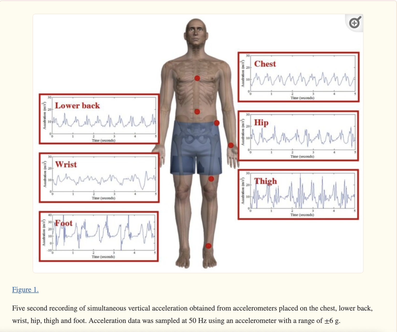
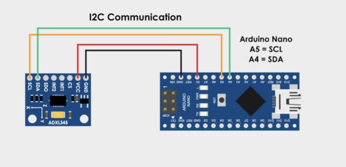

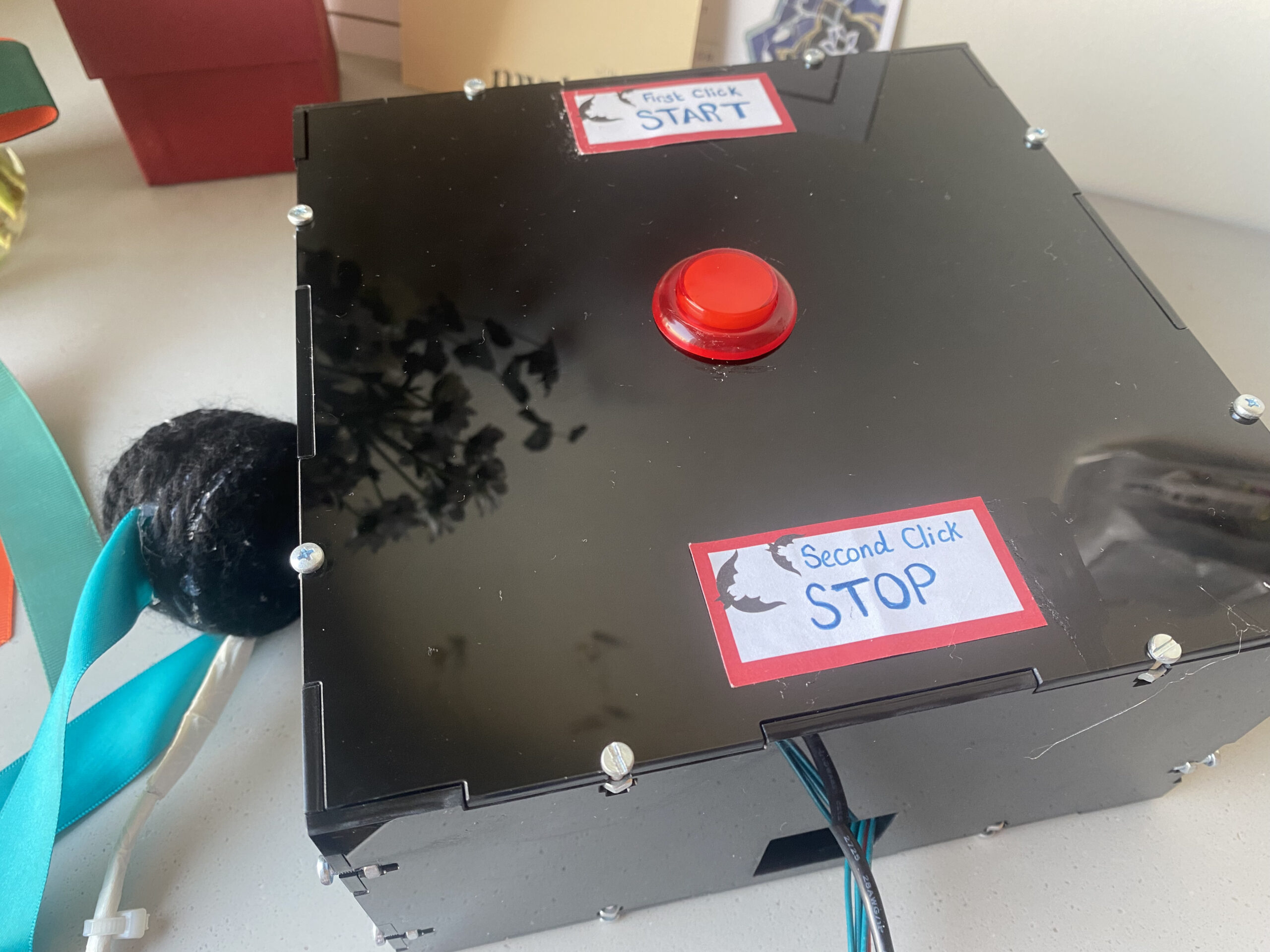
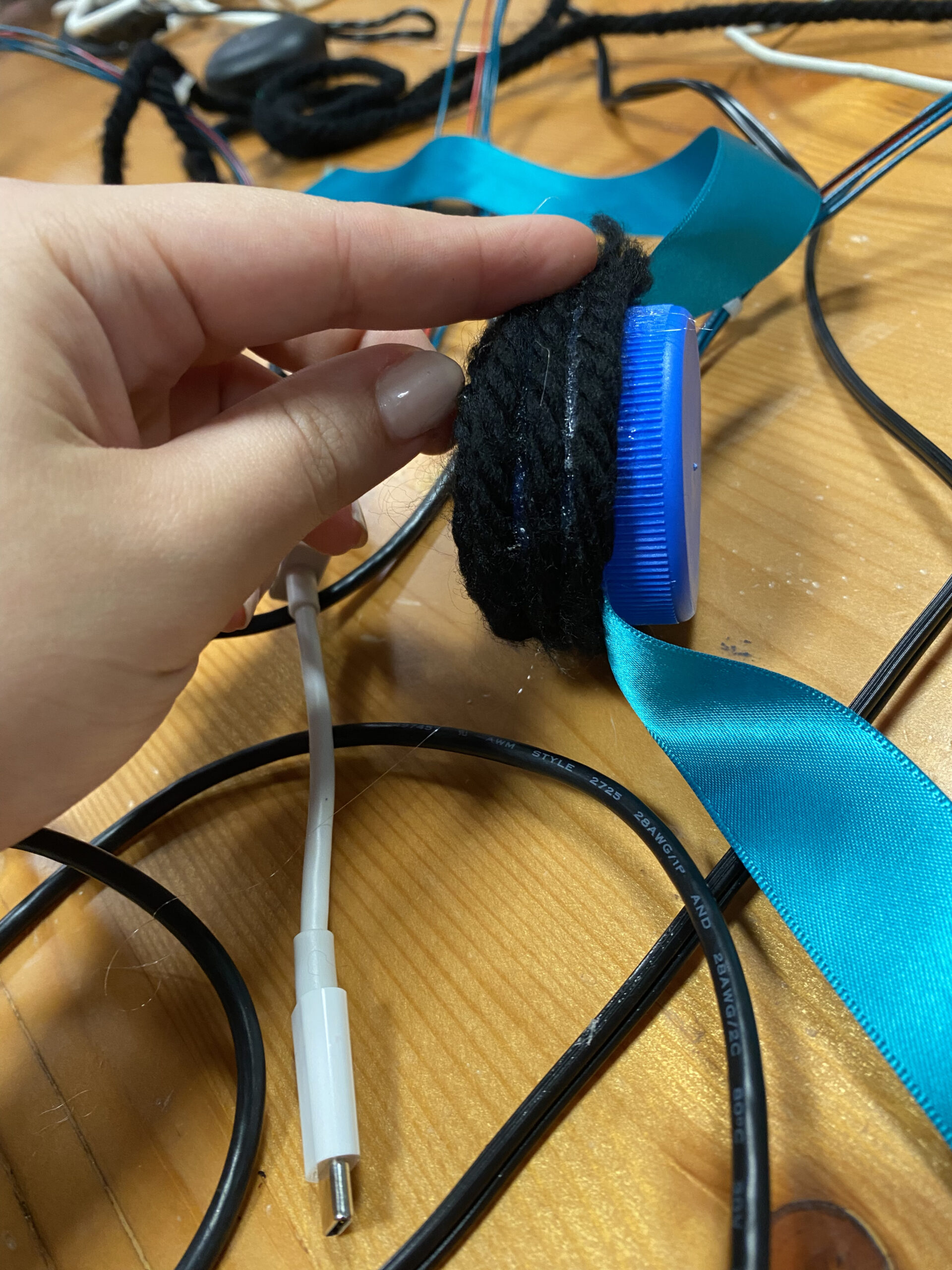
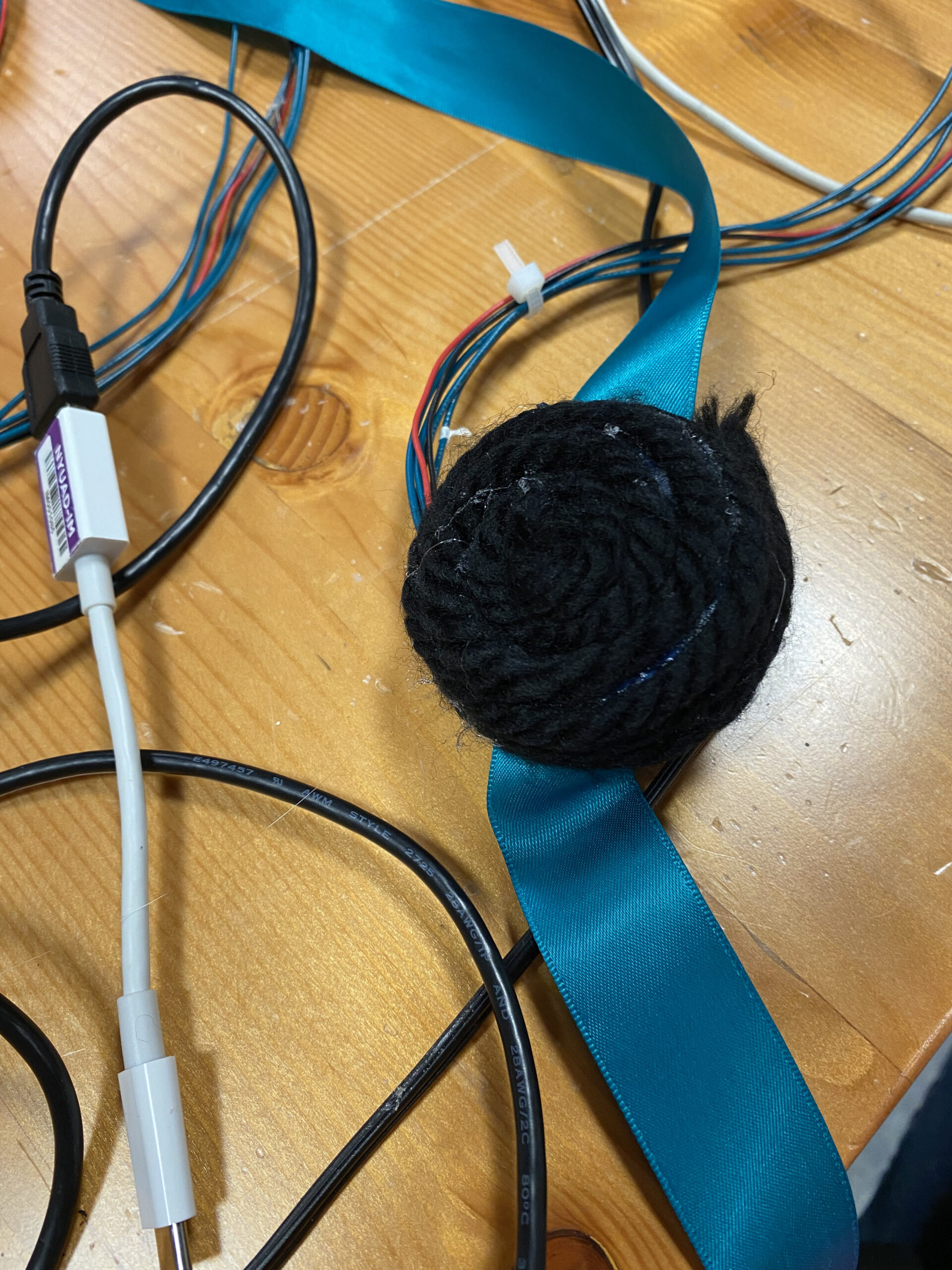
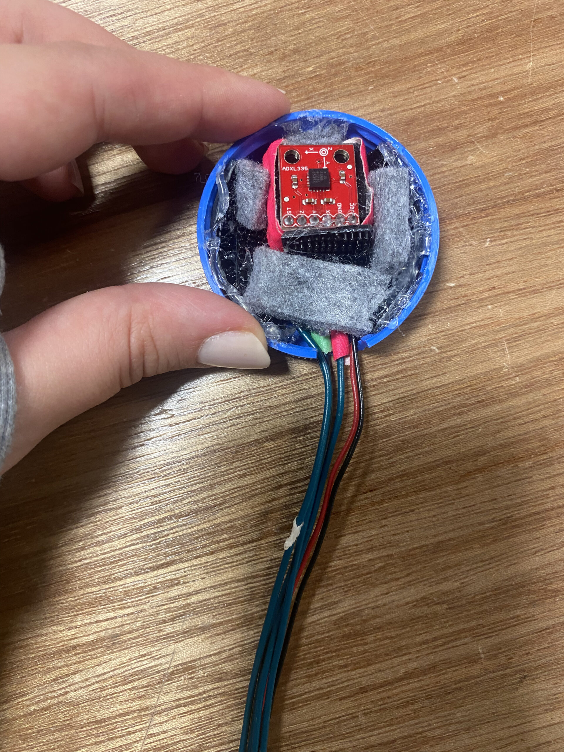


 Exhibition

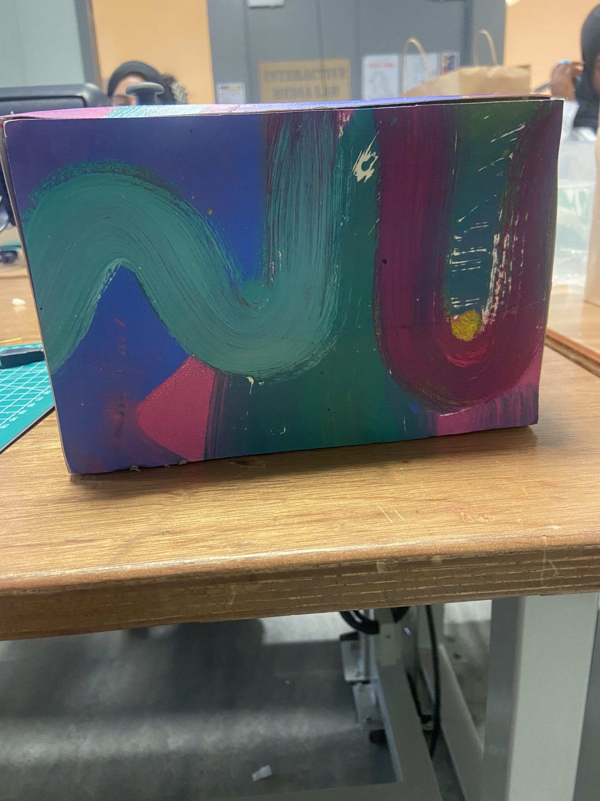
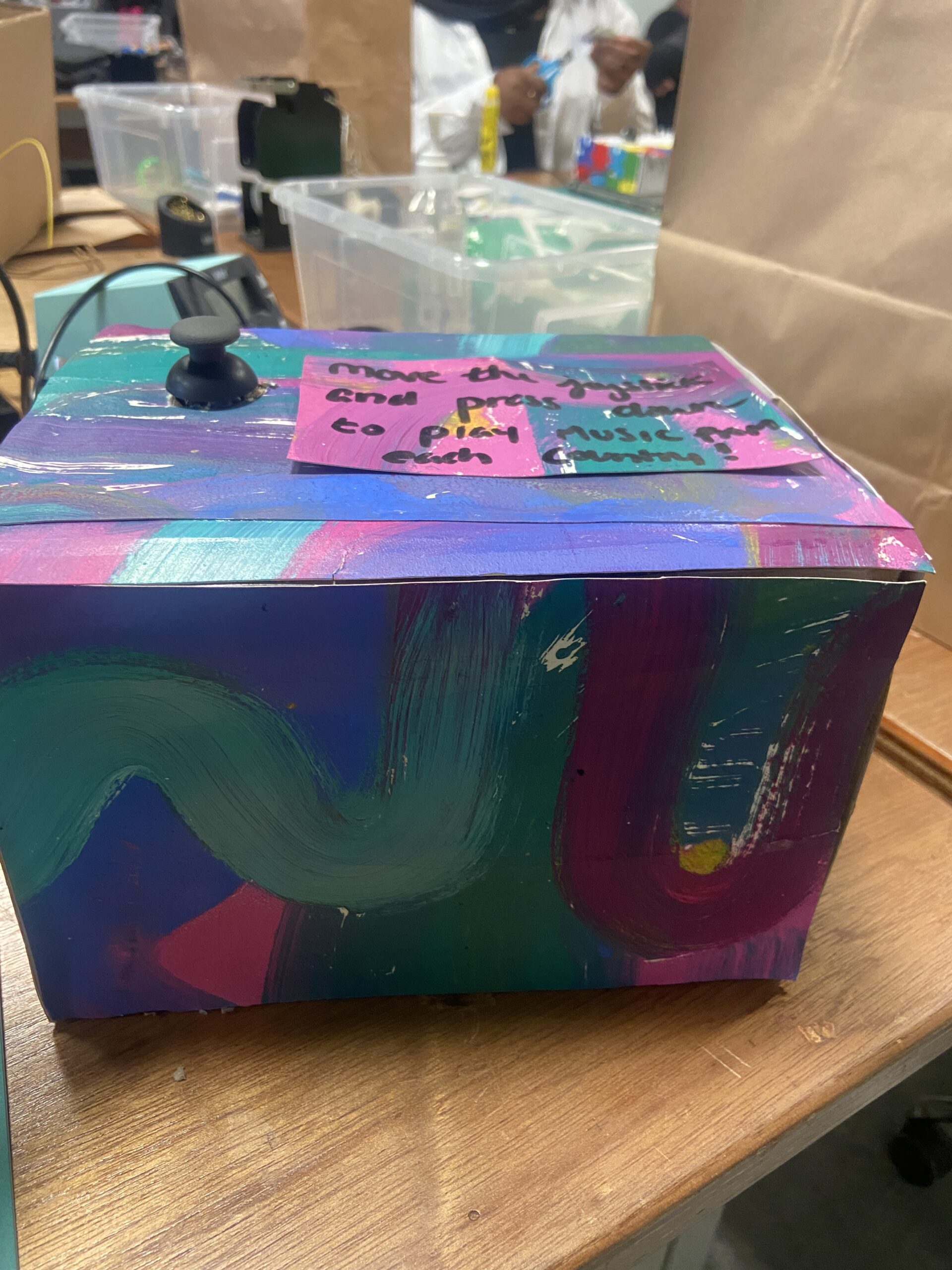
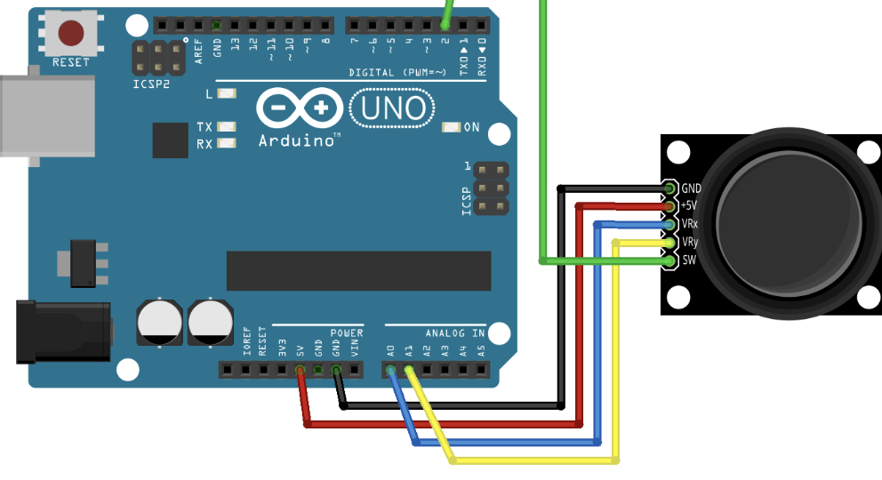
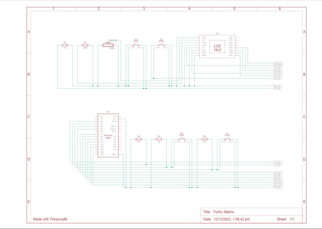
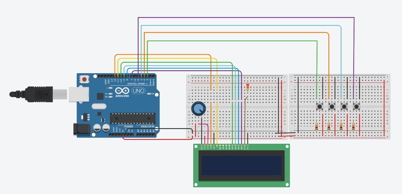
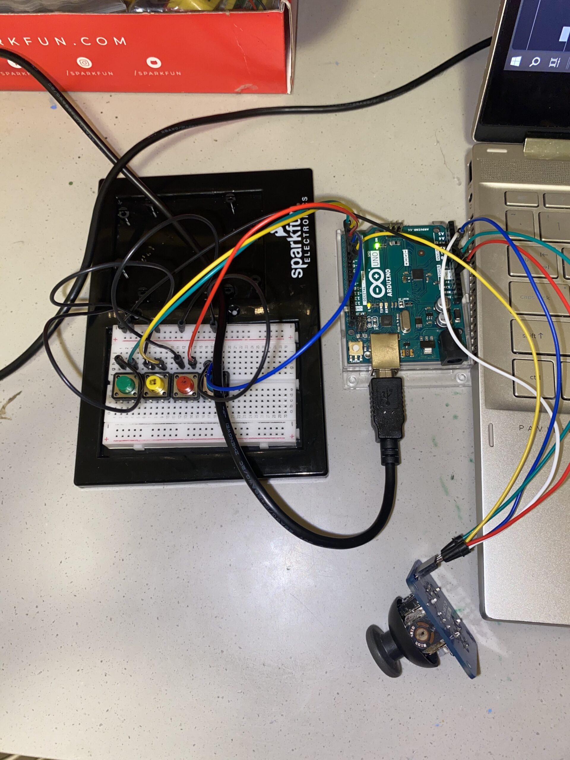
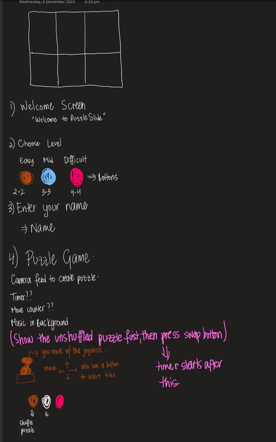
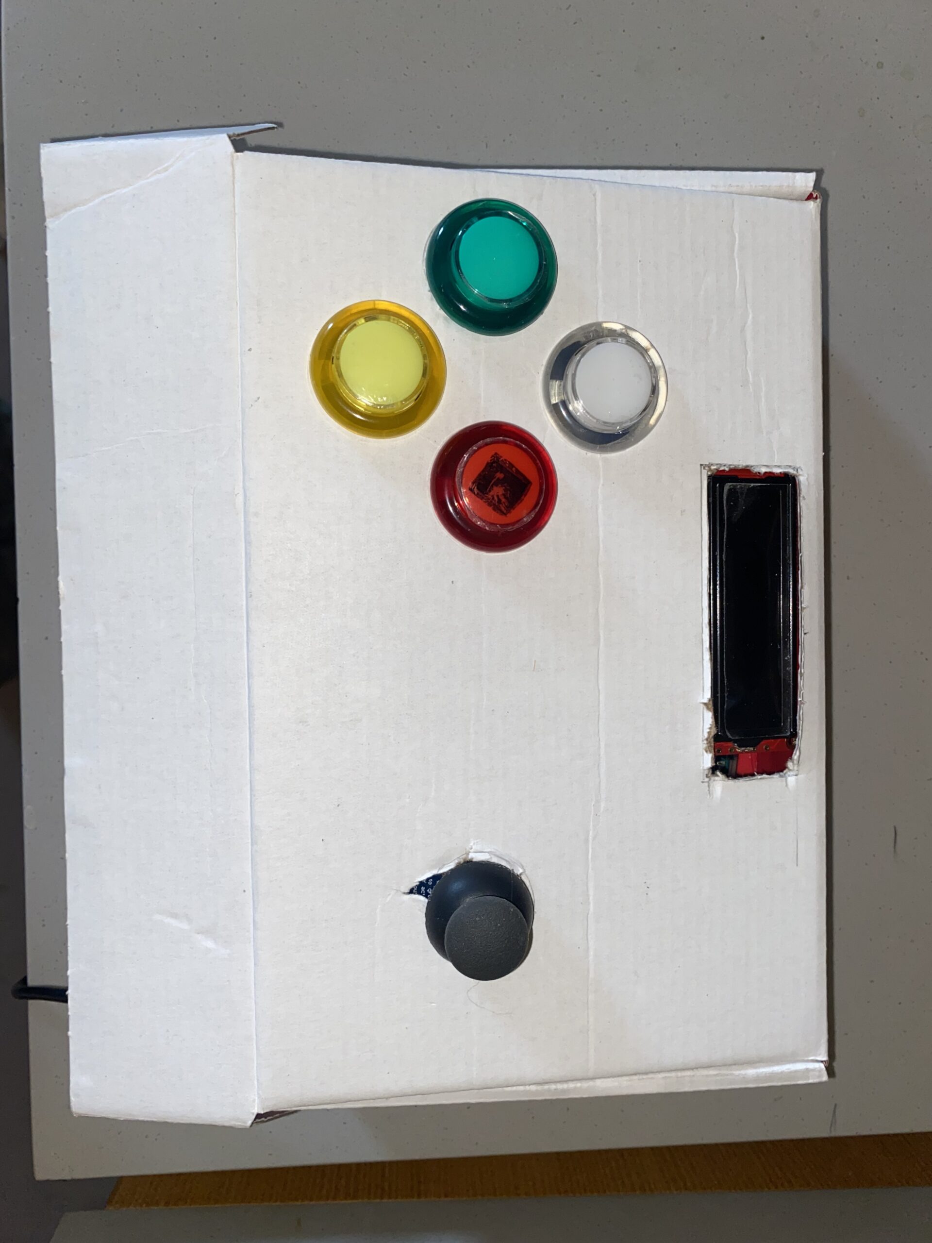
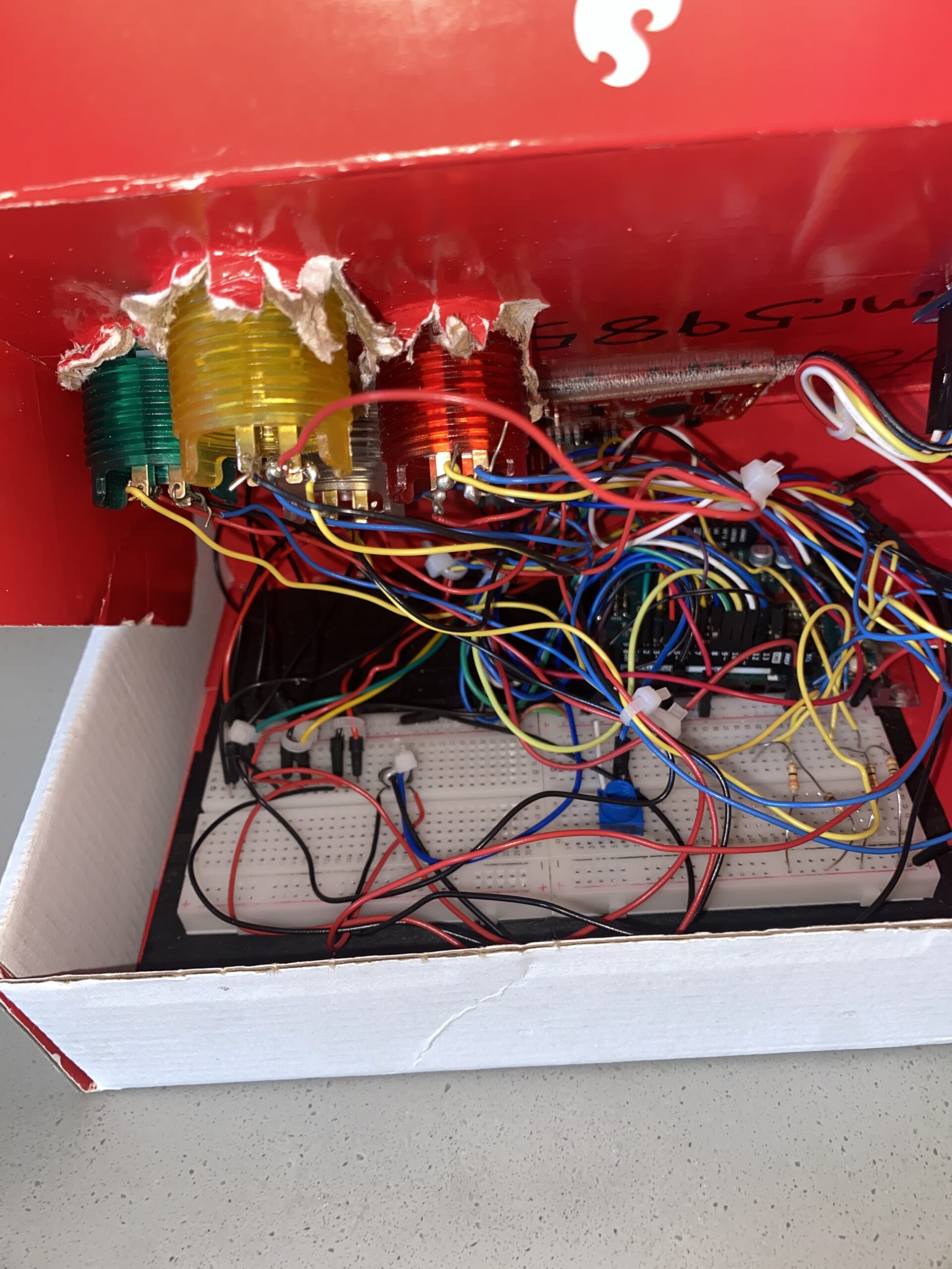
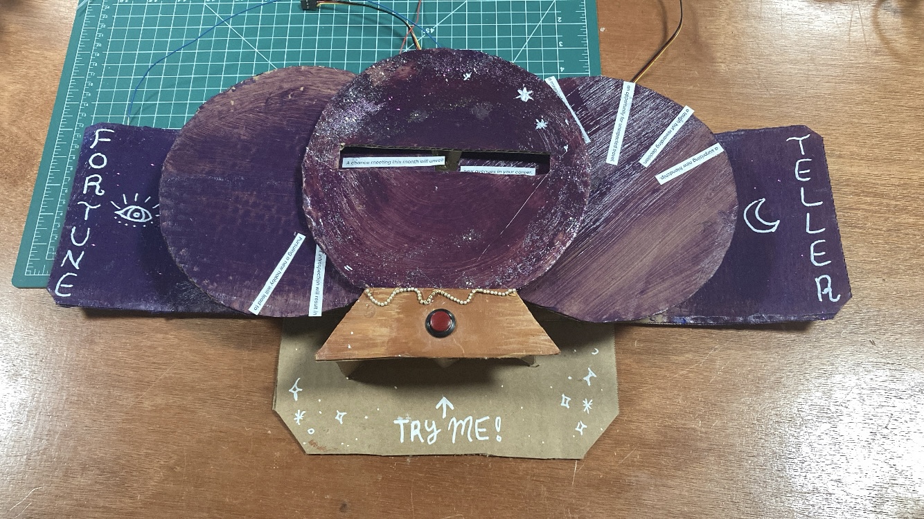
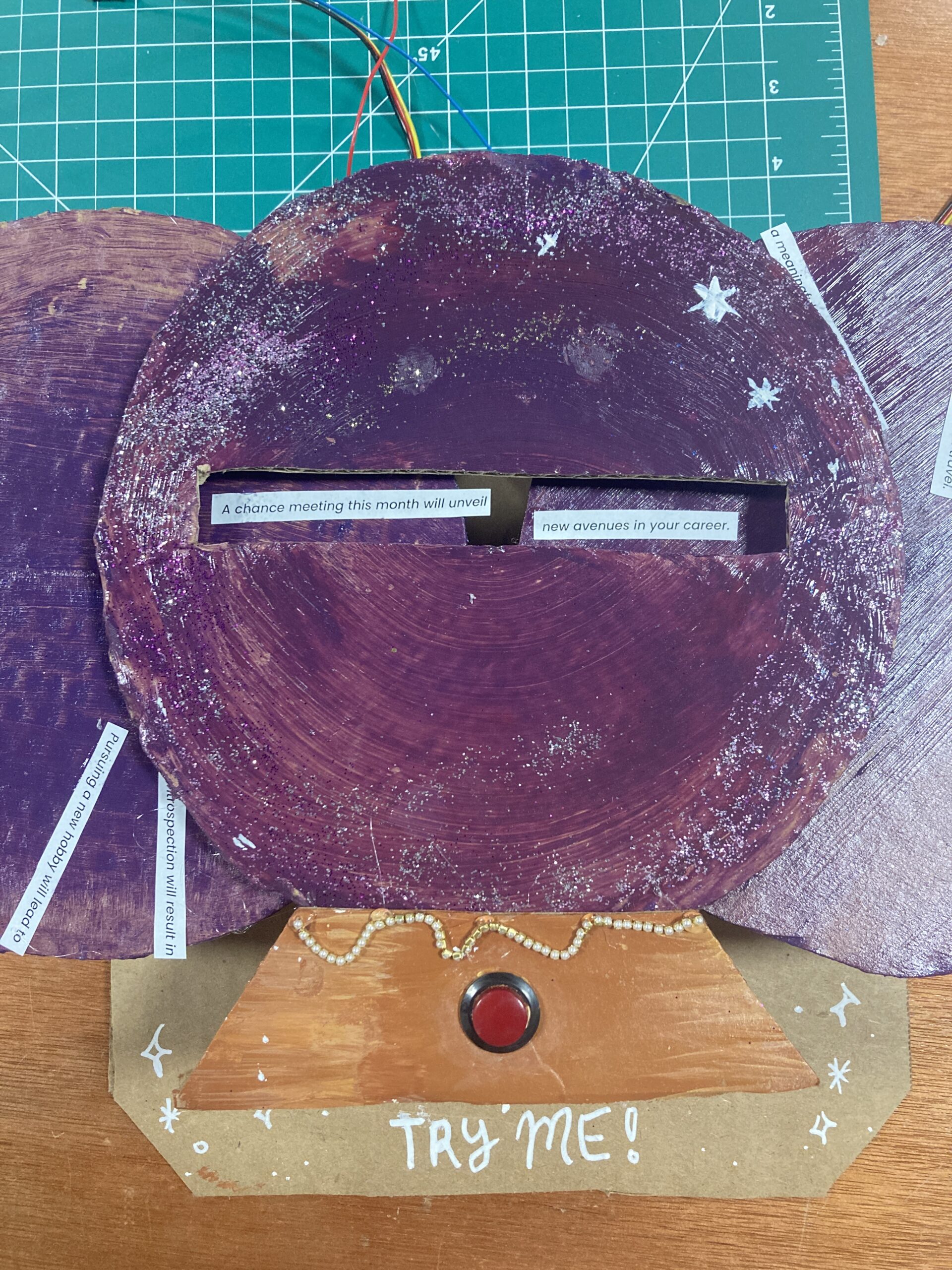
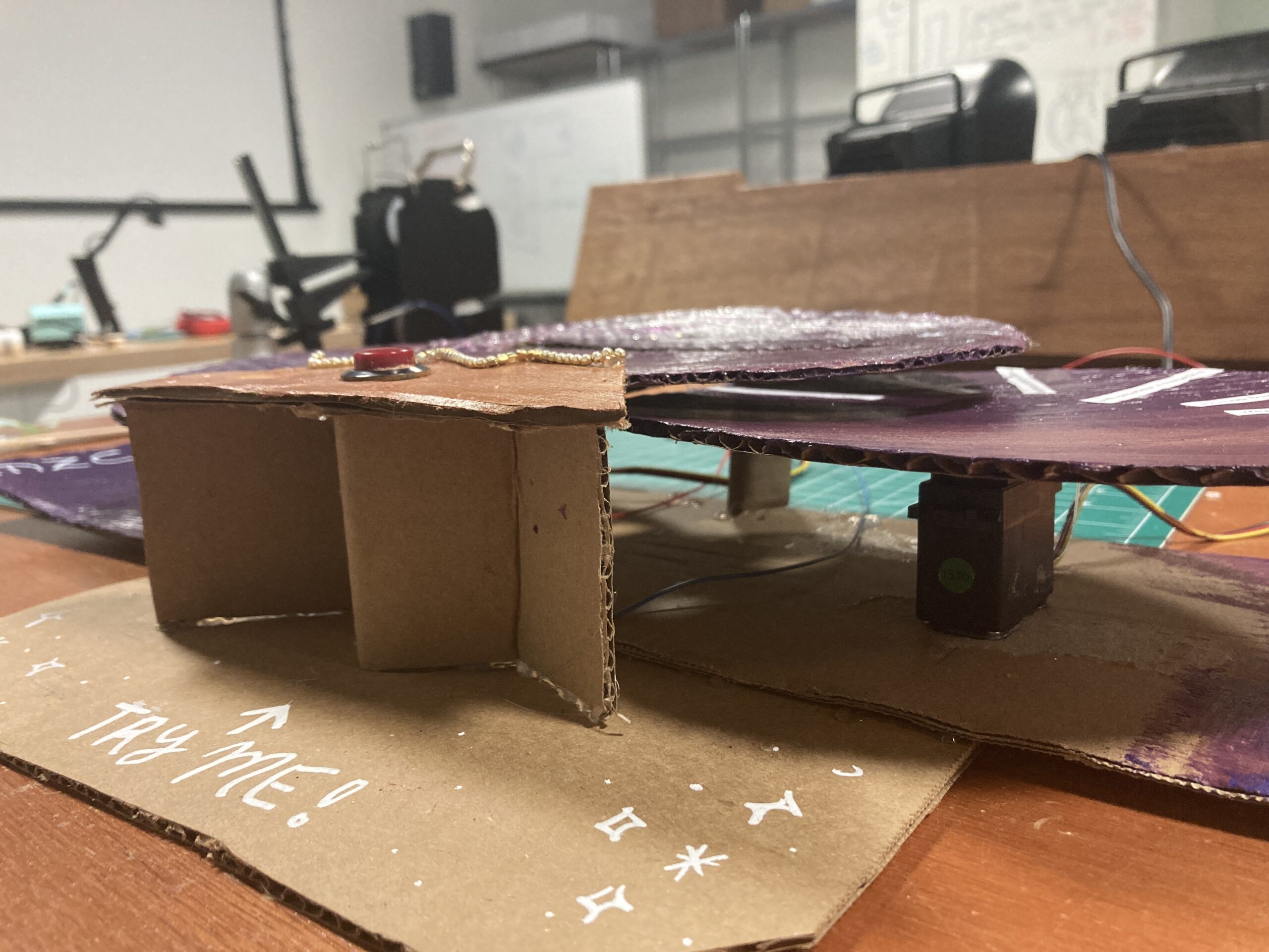
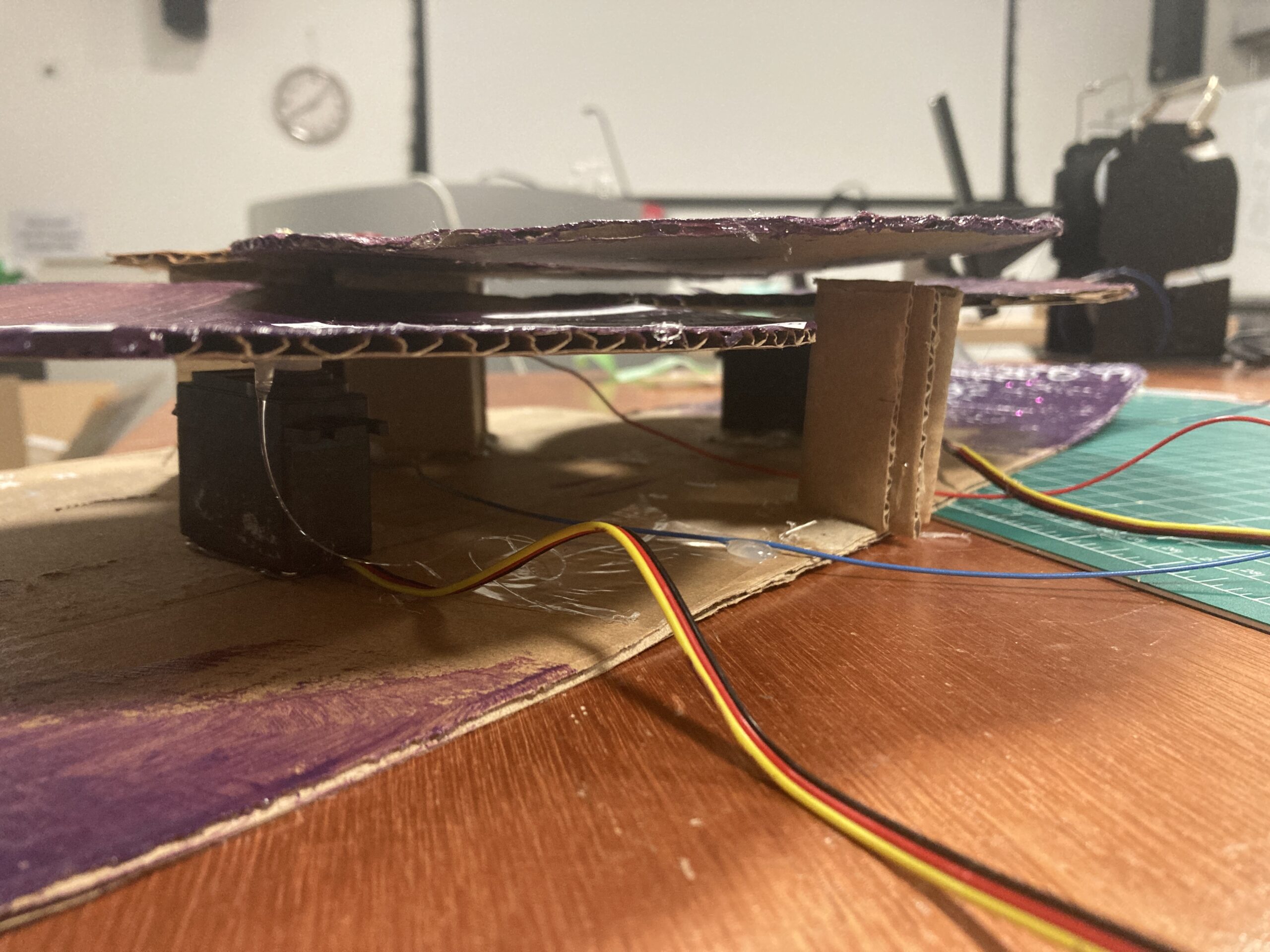
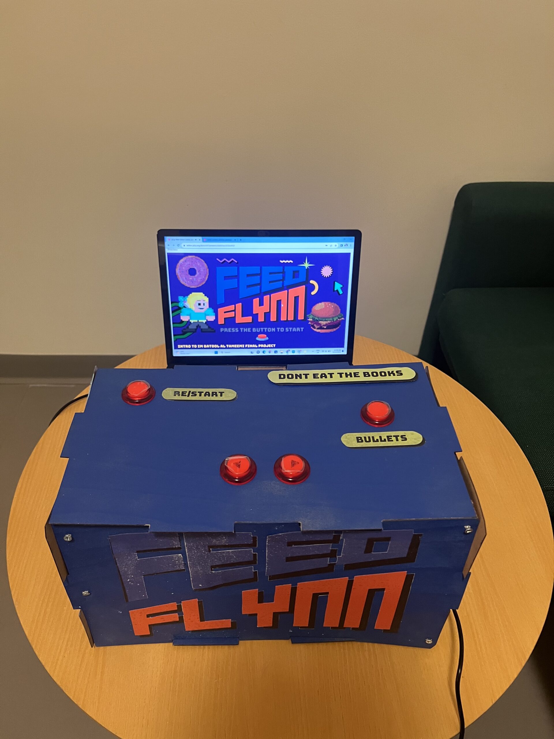
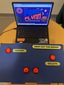
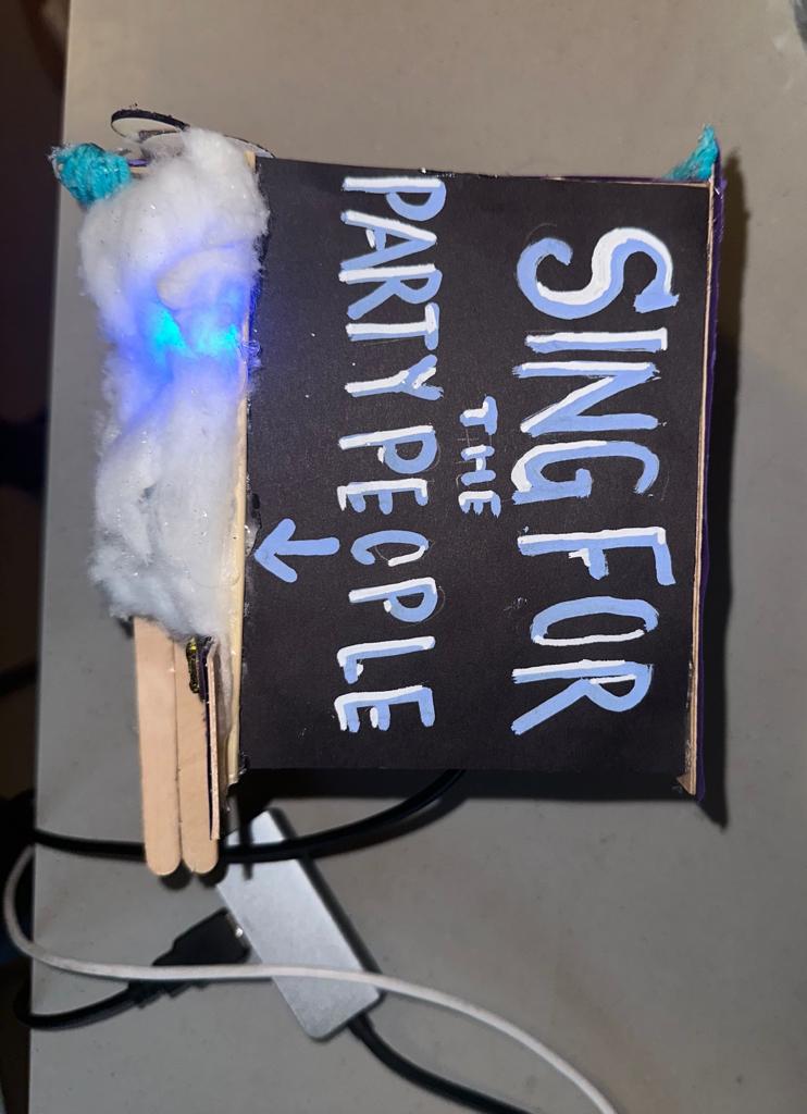
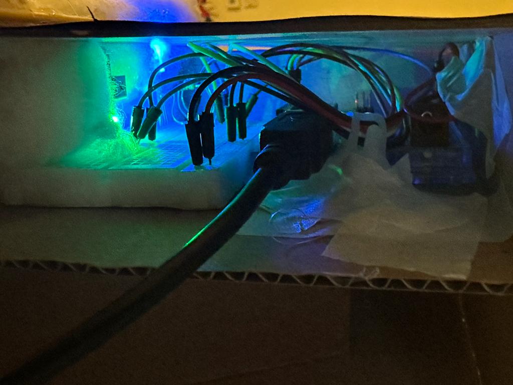

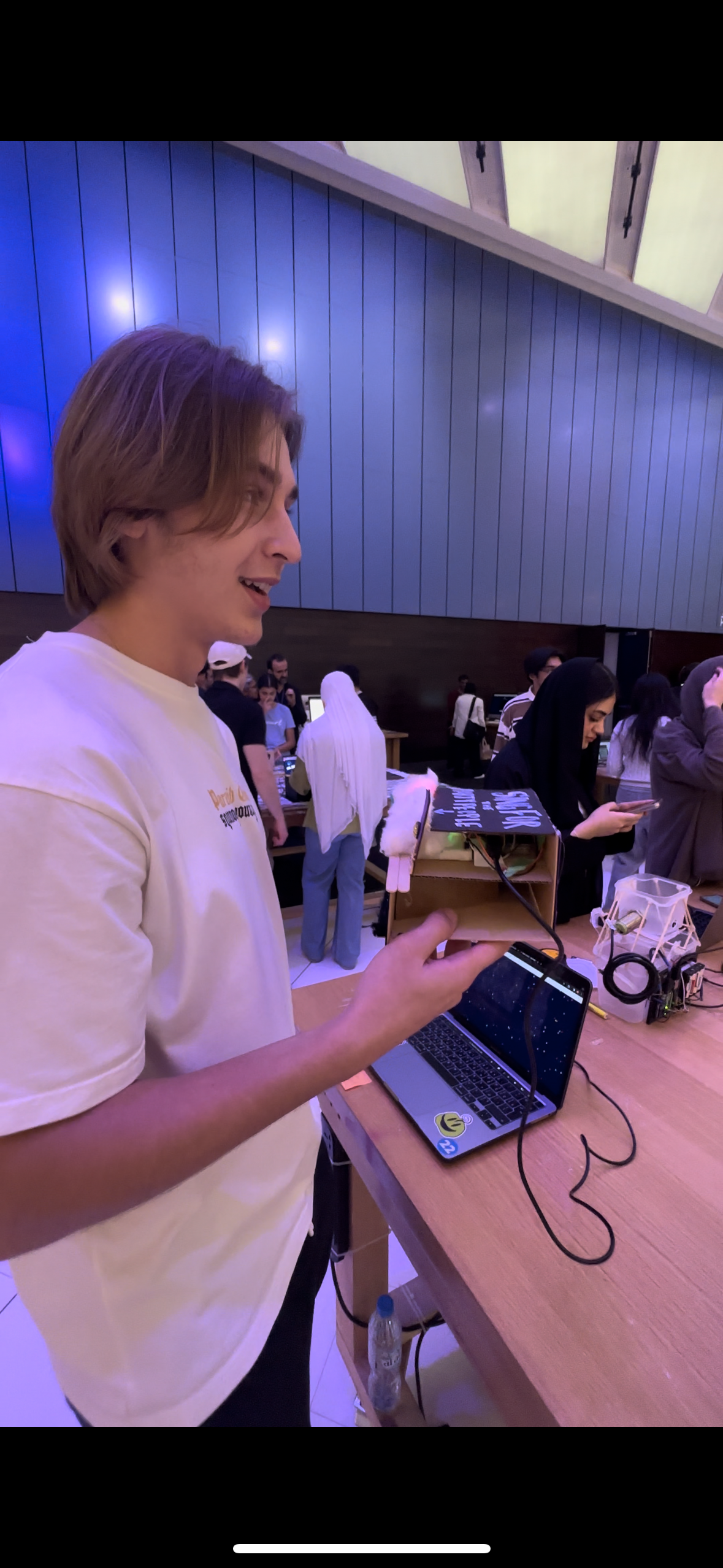
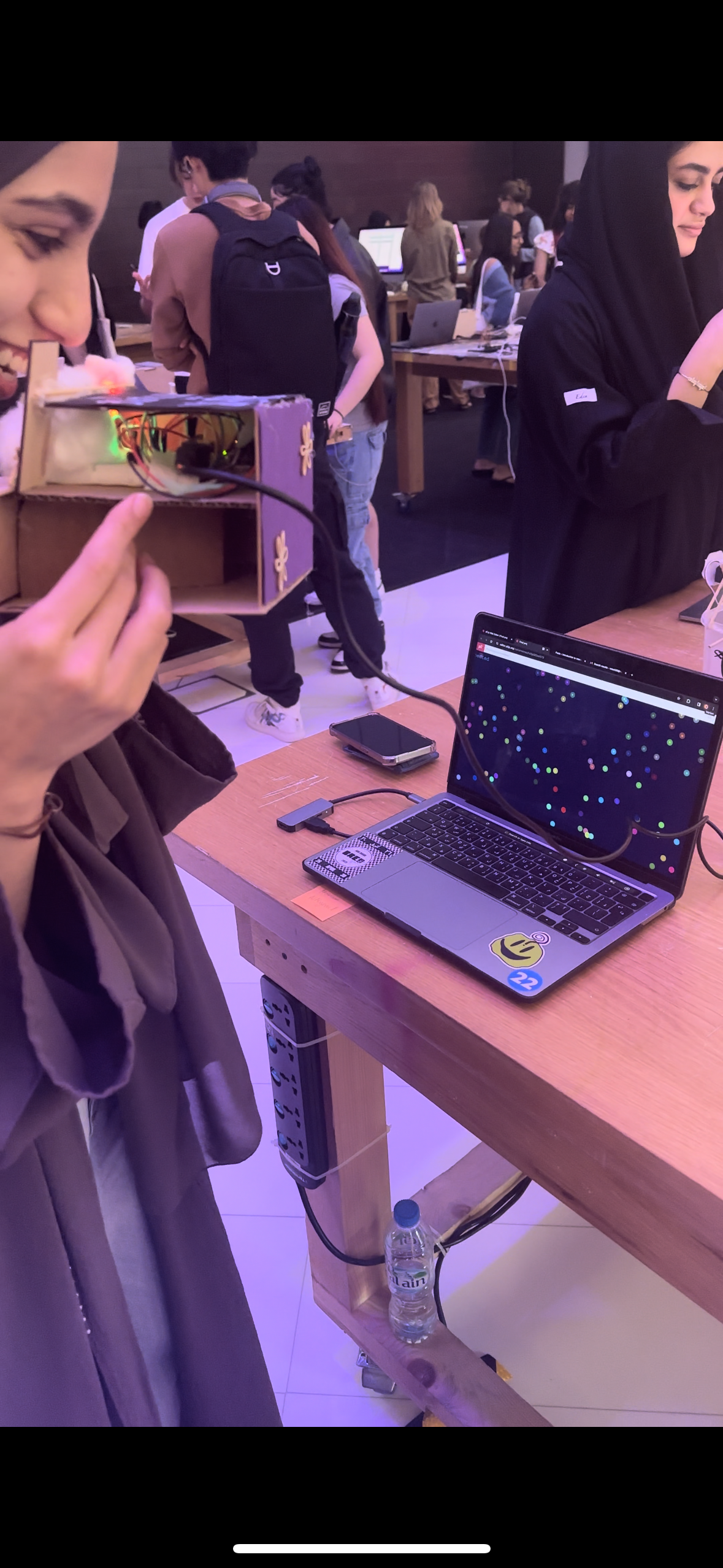
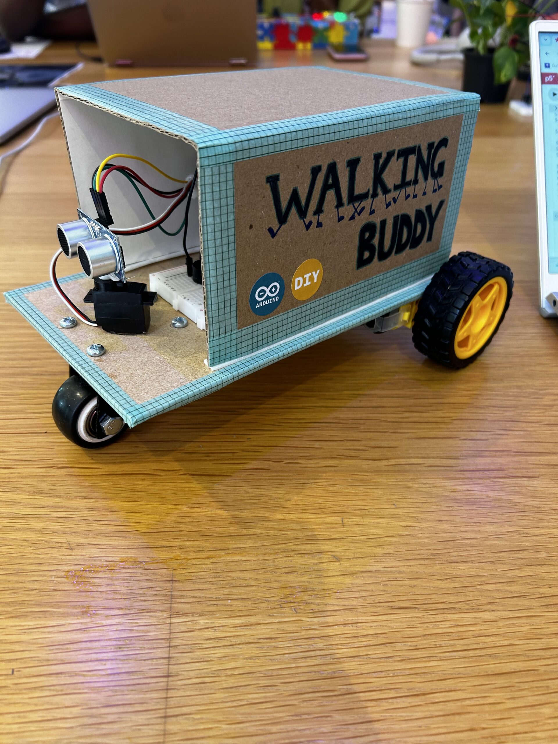
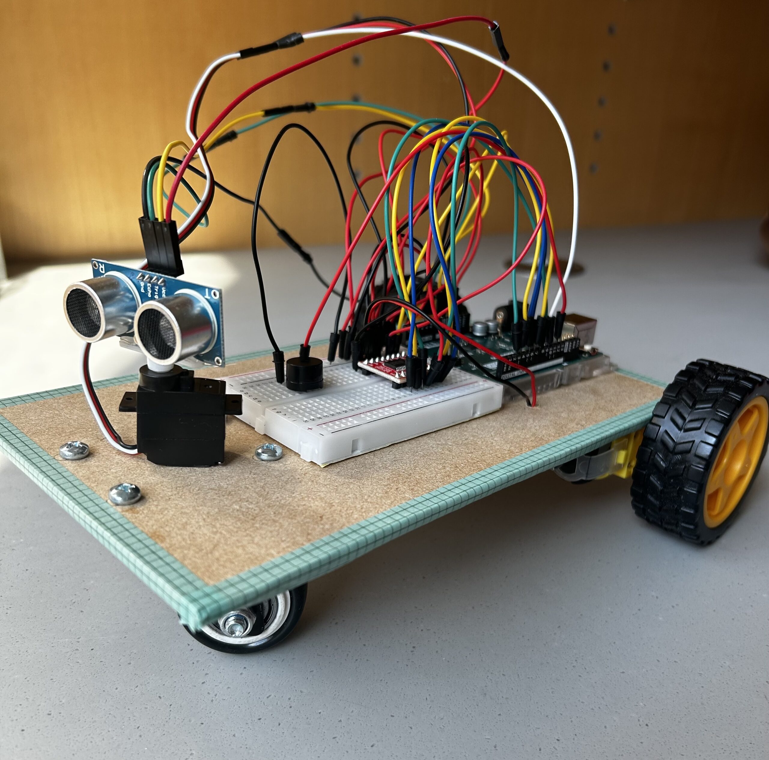
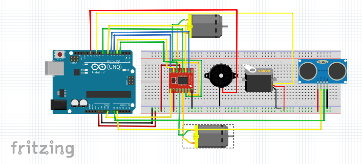
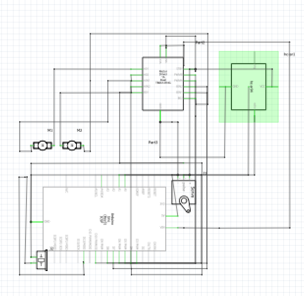
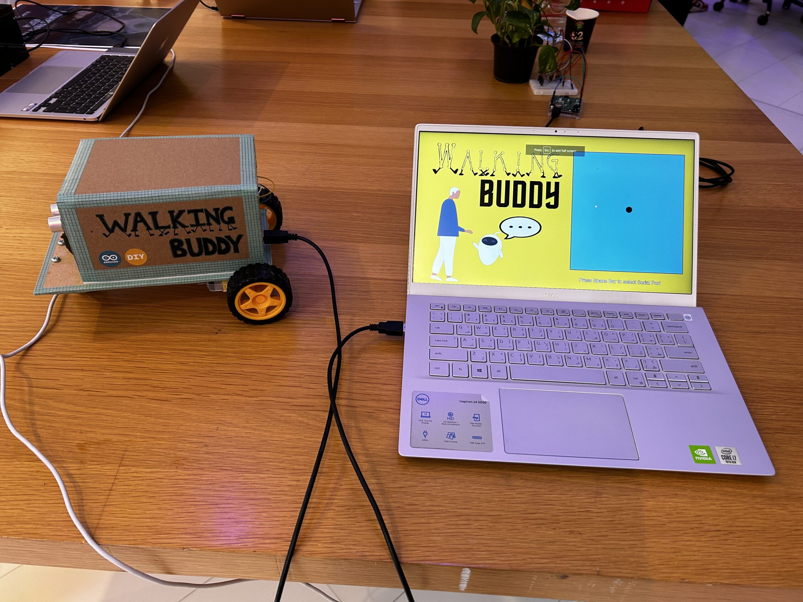
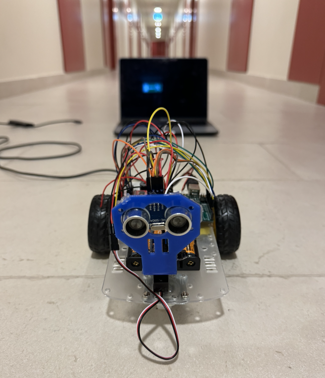
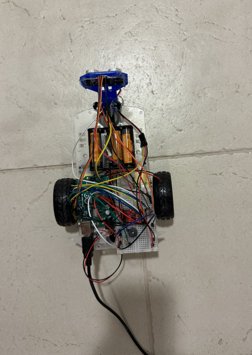
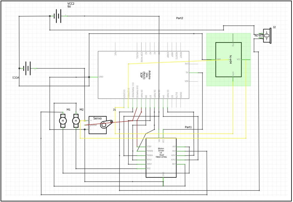
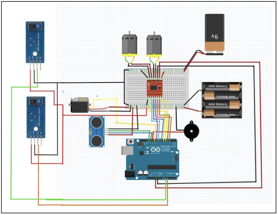