All Posts

Connecting Arduino to p5.js: in class exercises

EXERCISE 1

Extending the potentiometer example demoed in class, we created a smiley ball that bounces horizontally across the screen whose velocity was dependent on the value of the potentiometer. Inside our Arduino code, we write the value of the potentiometer as serial output to the p5.js sketch: 

void loop() {
  // put your main code here, to run repeatedly:
  int potentiomenter = analogRead(A0); 
  int mappedPot = map(potentiomenter, 0, 1023, 0, 255); 
  Serial.write(mappedPot); 
  delay(100); 

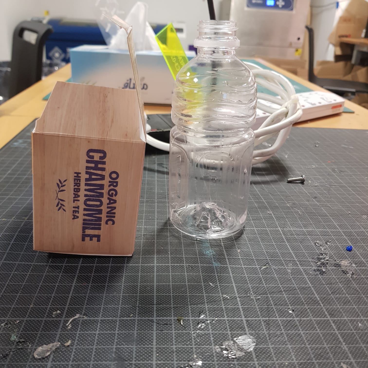
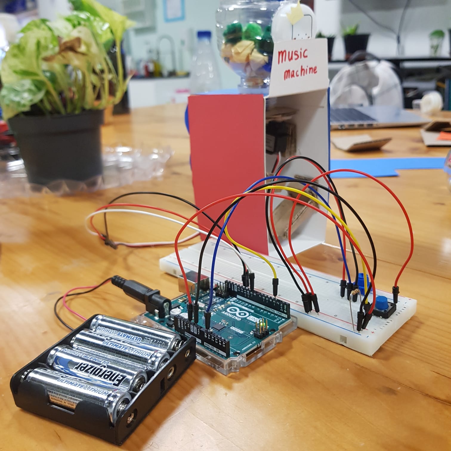
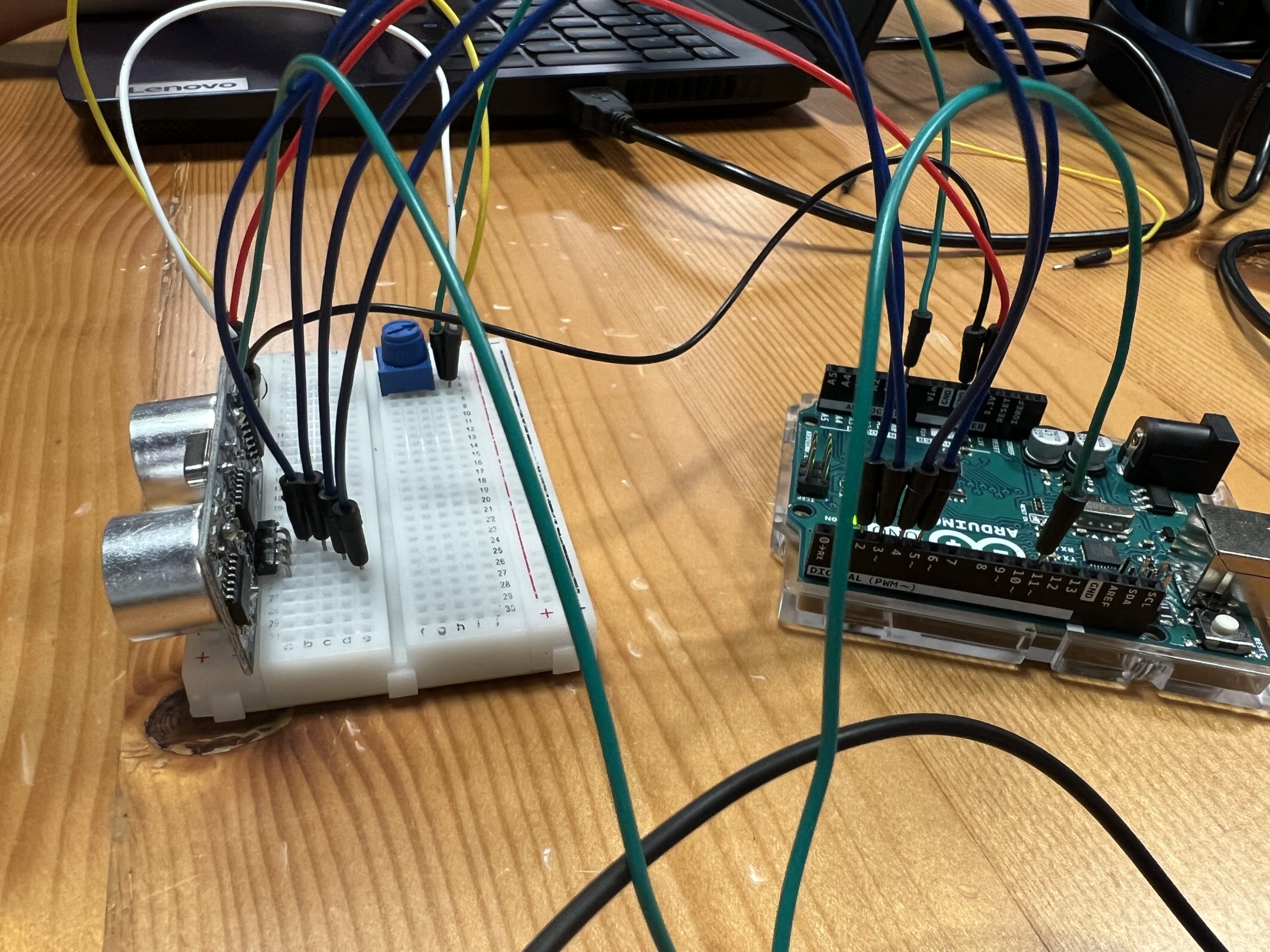
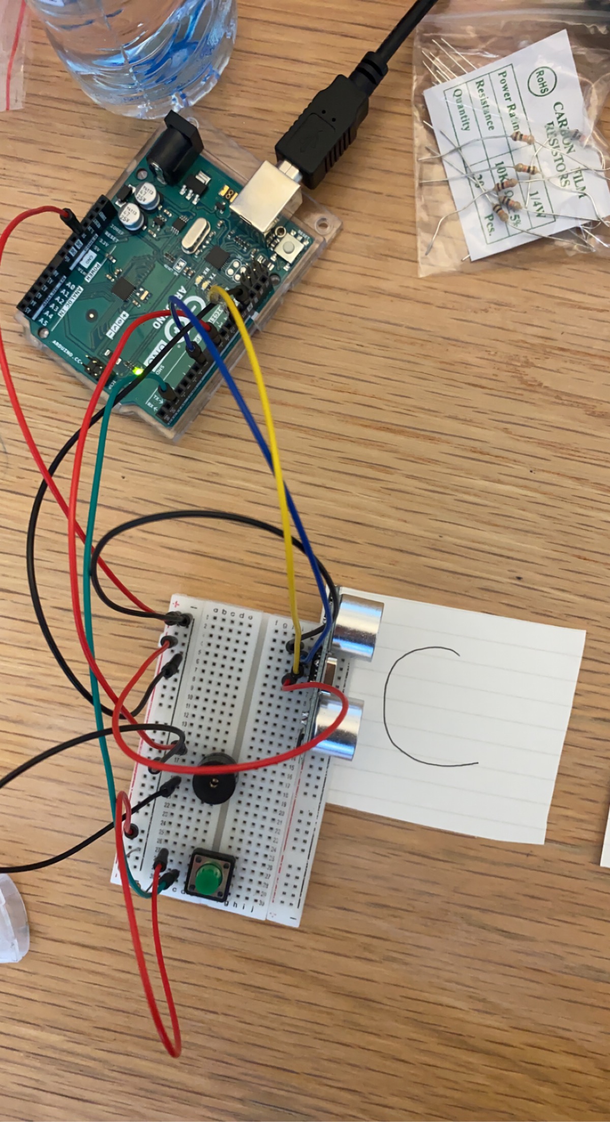
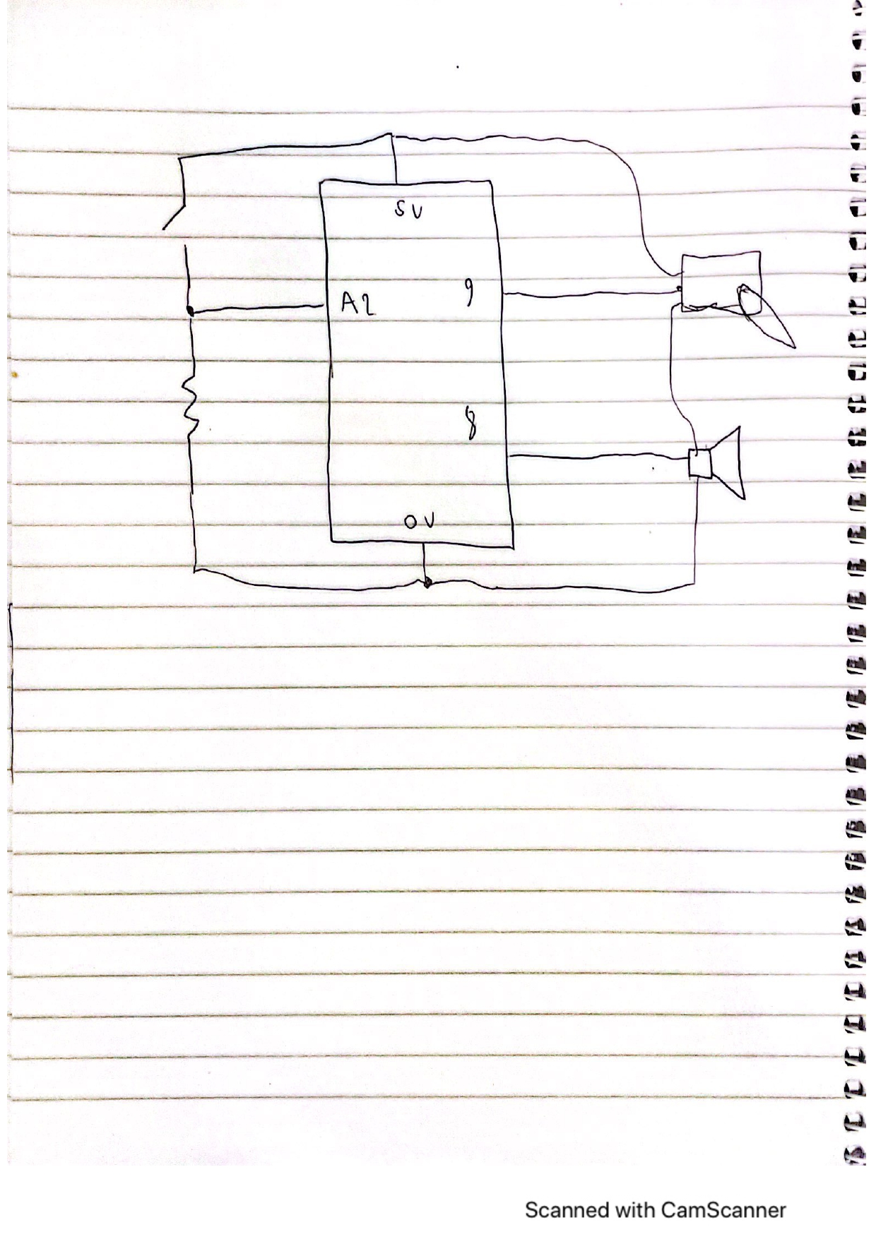
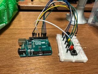
The corresponding breadboard is shown below: 

[image]

Inside our p5.js sketch, we created our smiley ball by making a simple Circle class with an x and y position and a move() method. The move method() doesn’t change the ball’s y position, as it remains constant along the horizontal axis height/2, but it does update the x position, which is calculated using the variable inData – the value of the potentiometer read from Arduino. A snipped of the code is shown below: 

class Circle {
  constructor(x, y, d) {
    this.x = x;
    this.y = y;
    this.d = d;
  }
  move() {
    if (this.x<=50) {x = 1;}
    else if (this.x>=550) {x =-1;}
    
    let y;
    
    if (inData==undefined) {
      y=0;
    } else {
      y = inData;
    }
     
    this.x+=(y/20)*x;
  }

Finally, a demo of the final product is shown below: 


EXCERCISE 2

We thought that the first exercise was rather bland in terms of visuals, so for this exercise we wanted our p5.js sketch to be more interesting. We made the connection of a sun rising and falling to the brightness of an LED, hence our sketch shows a sun against a mountain landscape that can “rise” and “fall” by pushing the up and down arrow keys. As the sun “rises”, the sky changes to a bright magenta color, and when the sun “falls”, the sky deepens to a dark blue color. We achieved this by having the sun’s y position (also built from the Circle class of Exercise 1) determine the rgb values of the background, as demonstrated in the following code:

function draw() {
  background(300-c.y, 100-c.y, 100+c.y); 
  c.display(); 
  c.move(); 
  
  var rightBrightness = map(c.y, height, 0, 0, 255);
  
  outData = rightBrightness;  // setup the serial output
  serial.write(outData); // write to serial for Arduino to pickup

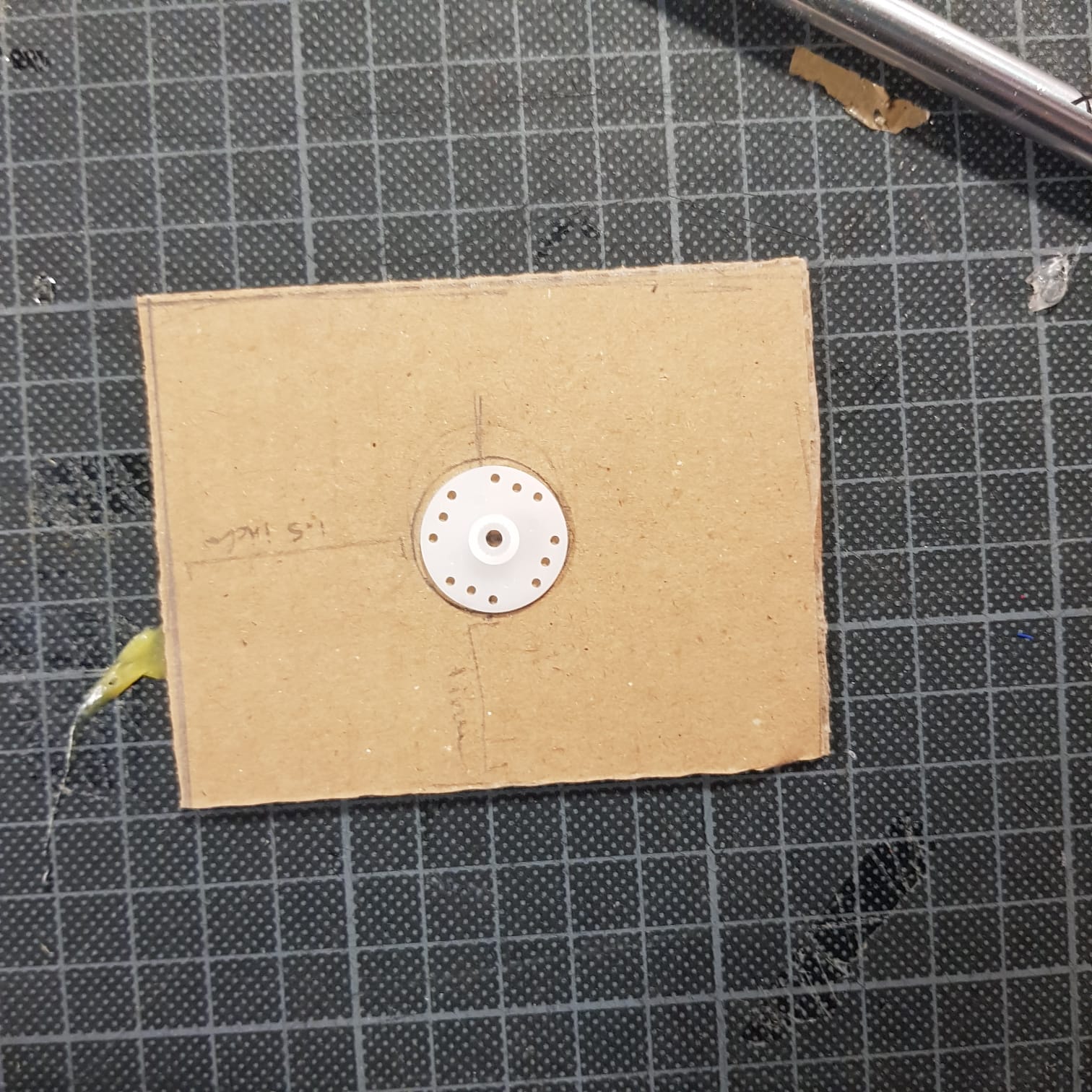
This seamless gradient effect then corresponds to the brightness of an LED on our Arduino board. 

[image]

The sun’s y position is stored as outData, which is then sent to Arduino. Inside our Arduino code, we map the incoming value to a scale of 0 to 255 and use that value to analog write the LED brightness. A snippet of this code is shown below: 

void loop() {
    if (Serial.available() > 0) { // see if there's incoming serial data
      incomingByte = Serial.read(); // read it
      led2brightness = map(incomingByte, 0, 255, 0, 255); // map the input value to the brightness for second LED
    } else { }
    analogWrite(ledPin, led2brightness); // write the brightness to the led pin 2
    
}


Finally, a demo of the finished product is shown below:
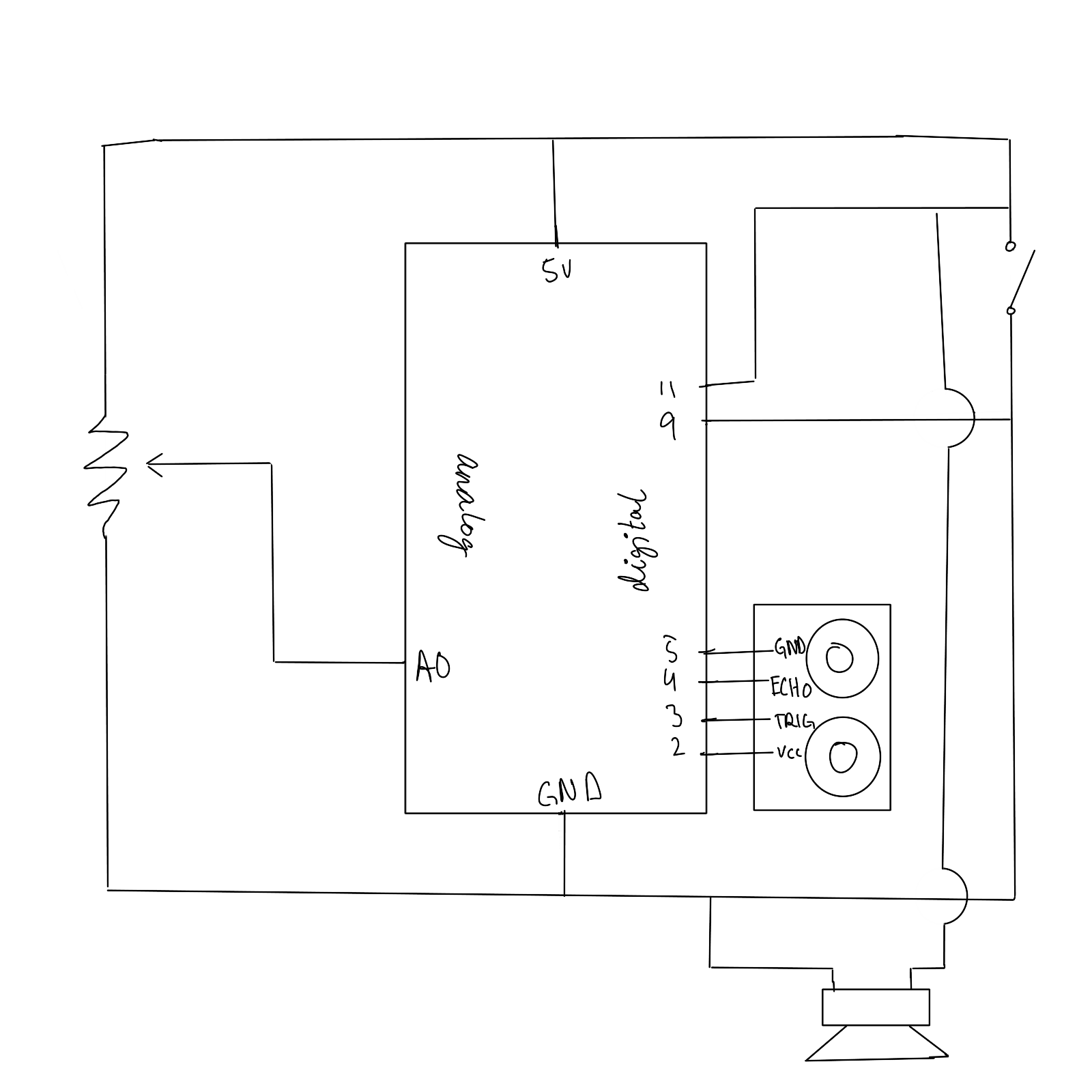
 

EXERCISE 3 

For the final exercise we were required to incorporate bidirectional serial communication, basically using the arduino to control a p5js sketch, and using changes in the p5js sketch to produce changes to the arduino. On the arduino, we used a distance sensor to affect the change of wind in p5js to make the ball move. On the p5js sketch we programmed it in such a way that everytime the ball bounces an LED lights up depending on the velocity of the ball.

Possible Final Project Concept(s)

Concept

I came up with two potential concepts so far:

  1. A flappy bird-like game where a character goes up and down according to either:
  • Value of photoresistor (how dark the area around it is determines whether the character goes up or down)
  • Value of potentiometer (how the number you get from turning the dial determines whether the character goes up or down)
  • Volume of voice
  • Force Sensing Resistor

to avoid the protruding obstacles.


  1. A radio that changes FM and AM values according to what number you turn the potentiometer dial to (I will input song files that play according to their designated potentiometer value).
  • Each value will take you to a different era of music

Components

 Flappy Bird:

  • p5, Arduino UNO, and breadboard
  • Photoresistor OR potentiometer OR Force Sensing Resistor
  • Wires
  • LED?

Radio:

  • p5, Arduino UNO, and breadboard
  • Potentiometer(s) – possibly one for AM and one for FM?
  • Wires


The circuits for both are relatively simple, I will use the serial monitor values to input into p5.

p5 Design Elements

Flappy Bird:

  • Character
  • Protruding obstacles
  • Background
  • Play and Game Over screens?

Radio:

  • Vintage radio screen
  • Dials design (AM/ FM dials on the screen move according to which potentiometer you move?)
  • Serial monitor value displayed (with digital clock font) that change accordingly

Last week’s class exercise

Potentiometer and p5 Video

Daniel, Aayat, and I made it so that whenever you turn the potentiometer dial, the circle would either go up or down according to the serial value.

We did this by replacing the y coordinate of the ellipse to inData in p5 (which displays the serial value in numerical terms).

ref. to function draw () {}

p5 Code

// variable to hold an instance of the p5.webserial library:
const serial = new p5.WebSerial();
 
// HTML button object:
let portButton;
let inData;
// for incoming serial data
let outByte = 0;              // for outgoing data
 
function setup() {
  createCanvas(400, 300);          // make the canvas
  // check to see if serial is available:
  if (!navigator.serial) {
    alert("WebSerial is not supported in this browser. Try Chrome or MS Edge.");
  }
  // if serial is available, add connect/disconnect listeners:
  navigator.serial.addEventListener("connect", portConnect);
  navigator.serial.addEventListener("disconnect", portDisconnect);
  // check for any ports that are available:
  serial.getPorts();
  // if there's no port chosen, choose one:
  serial.on("noport", makePortButton);
  // open whatever port is available:
  serial.on("portavailable", openPort);
  // handle serial errors:
  serial.on("requesterror", portError);
  // handle any incoming serial data:
  serial.on("data", serialEvent);
  serial.on("close", makePortButton);
}
 
function draw() {
  
   background(0);
   fill(255);
   text("sensor value: " + inData, 30, 50);
  ellipse (200, inData, 50, 50)
  
}

// if there's no port selected, 
// make a port select button appear:
function makePortButton() {
  // create and position a port chooser button:
  portButton = createButton("choose port");
  portButton.position(10, 10);
  // give the port button a mousepressed handler:
  portButton.mousePressed(choosePort);
}
 
// make the port selector window appear:
function choosePort() {
  if (portButton) portButton.show();
  serial.requestPort();
}
 
// open the selected port, and make the port 
// button invisible:
function openPort() {
  // wait for the serial.open promise to return,
  // then call the initiateSerial function
  serial.open().then(initiateSerial);
 
  // once the port opens, let the user know:
  function initiateSerial() {
    console.log("port open");
  }
  // hide the port button once a port is chosen:
  if (portButton) portButton.hide();
}
 
// pop up an alert if there's a port error:
function portError(err) {
  alert("Serial port error: " + err);
}
// read any incoming data as a string
// (assumes a newline at the end of it):
function serialEvent() {
  inData = Number(serial.read());
  console.log();
  
}
 
// try to connect if a new serial port 
// gets added (i.e. plugged in via USB):
function portConnect() {
  console.log("port connected");
  serial.getPorts();
}
 
// if a port is disconnected:
function portDisconnect() {
  serial.close();
  console.log("port disconnected");
}
 
function closePort() {
  serial.close();
}

Arduino Code

void setup() {
  Serial.begin(9600); // initialize serial communications
}
 
void loop() {
  // read the input pin:
  int potentiometer = analogRead(A0);            
  // remap the pot value to fit in 1 byte:
  int mappedPot = map(potentiometer, 0, 1023, 0, 255); 
  // print it out the serial port:
  Serial.write(mappedPot); 

    // slight delay to stabilize the ADC:
  delay(1);                                                          
                                      
  
  // Delay so we only send 10 times per second and don't
  // flood the serial connection
  delay(100);
}


Final Project: Concept

Inspiration: Etch a Sketch

Source: The New York Times Magazine

Etch a Sketch is a simple drawing tool. Users can rotate two knobs to alter x and y positions of a drawing dot, creating a continuous drawing. To erase the drawn image, users have to shake the board.

Brainstorming

Creating an Arduino version of Etch and Sketch does not seem to be too difficult, so I am thinking of a few things that make the Arduino version somewhat unique. However, there are a few guidelines I would like to maintain:

      1. Since it is a drawing tool, the control of the dot has to be precise.
      2. Related to (1), the final product should be intuitive to use.

So, the Arduino version of Etch and Sketch will likely have potentiometers to act as knobs and a button to erase the drawing. The below is the list of additional features that may or may not be implemented in my project:

      1. 3D. Introducing another drawing axis, people can create a 3D drawing. However, this may be a challenging task, and other features may not be implemented if I focus on creating this.
      2. Partial erasing. Similar to how texts are erased on smartphones, people will be able to undo their drawing, and erasing will become faster if keep erasing.
      3. Color/stroke thickness.
      4. Pause/Resume drawing. Similar to lifting a pen to draw things on another side, the drawing of the dot may pause and resume at any time. Maybe this can be implemented with the color feature using RGBA.


Hopefully, unlike my midterm project, the final product of this project will be not too complex.

Piano by Hessa&Zhaniya

For this week’s assignment, we wanted to design a mini piano using switch buttons. Our goal was to make each button have a different note so that when users play the piano they can recreate the sound from the “Happy Birthday” song. We also added a potentiometer to our circuit so that we could regulate the volume of the sound.

Image of notes:

To build the circuit we added switch buttons and resistors and connected the wires to the pins. We downloaded pitches from examples→toneKeyboard, each switch button had its own musical note from the song(C5, B4, A4, G4, D5). We struggled a bit with adding potentiometer and piezo buzzer to our circuit with piano buttons, however we managed to solve the problems and understand the process.

At the beginning we initialized the piano buttons, buzzer and potentiometer. Next, we went on to add the code for the buzzer and potentiometer. We wrote code to read the input on the analog pin and turn the piezo buzzer on and off. Also, we set a tone for each button and activated it. To improve this work, next time we can add more buttons and play new songs:)

Final code:
Link to GitHub

Final result:
IMG_6078

Analog input & output

Concept:

Analog input and output is a fundamental concept in electronics and microcontrollers, such as the Arduino. In this project, we will be using analog input and output to control a pair of LEDs, one red and one blue, which will mimic the flashing lights of a police car. This will be achieved by using a sensor, such as a motion sensor, to detect when a hand is waved in front of the LEDs. The reason for choosing this particular project is to gain a better understanding of analog input and output, as well as to create a fun and interactive project using the Arduino. By using a sensor to control the flashing of the LEDs, we can create a sense of realism and add an extra layer of interactivity to the project.

Reflections and improvements:

As someone who enjoys tinkering with gadgets and technology, working on an analog input and output project was a lot of fun for me. I was excited to see how the switch would work and how the output would be displayed on the screen. Unfortunately, the video of my project got corrupted and I was unable to show the switch in action (when pressed while the motion sensor was used the LED would flash).

Despite this setback, I was still happy with how the project turned out. The analog input and output functioned exactly as I had expected, and I was able to learn a lot about how these types of systems work. I enjoyed the process of building and testing the project, and it was satisfying to see it all come together in the end.

Looking back, there are a few things I would do differently if I had the chance to work on this project again. For one, I would make sure to back up the video of the project before showing it to others. This way, if something goes wrong with the video, I would still have a copy of it to refer to.

Assignment 7: Music Machine by Nouf and Vivianna

Our idea for the musical instrument was to use sounds that the servo motor created rather than incorporating the piezo buzzer. So, we decided to try and recreate a gumball machine and the sound it makes when the gumballs fall out of the machine.

The Physical Design Process

We built the structure using a box, water bottle and cardboard. We then prepared the servo motors and prepared a cardboard piece to act as a ball stopper to control the amount of balls that fall through the hole.

Box and water bottle for the structure
Servo motor ball stopper


We attached the servo motor and started testing out the servo motor with balls made from different materials to see what sound they made. We also decided to create two ramps for the balls to slide on to make more sound. As for the materials, we used pipe-cleaners, paper, and marbles. We found that the marbles made the best sound and rolled nicely down the ramp. The paper balls made a decent sound, whereas the pipe-cleaners were almost silent when they fell.


We attached the servo motor and started testing out the servo motor with balls made from different materials to see what sound they made. We also decided to create two ramps for the balls to slide on to make more sound. As for the materials, we used pipe-cleaners, paper, and marbles. We found that the marbles made the best sound and rolled nicely down the ramp. The paper balls made a decent sound, whereas the pipe-cleaners were almost silent when they fell.

Here is the final version of the physical components:

And here is the schematic of our circuit:

Some things that didn’t work out as expected…

Our initial plan was to have the balls fall down one by one, but that didn’t work as expected. The balls either fell together when the ball stopper opened, or they would get stuck even when the stopper opened. When they do fall down, most of the time they wouldn’t roll down the ramps as intended. Usually, the balls would fall to the side, fall straight down, or when it does fall on the slide it wouldn’t roll all the way down and it would get stuck on the ramp. In this case, the marbles worked best since they were smooth spheres, but the marbles also had the problem with falling to the side. Additionally, at first we wanted the stopper to open and close continuously after one button press, but currently it just does the cycle once and you have to keep pressing the button for the continuous opening and closing.

The Coding Process

For implementing the sensors, we decided to use a push button and potentiometer. We used the button to control the servo motor, which either blocks or unblocks the hole where the balls fall out of. When it is open the balls fall out, and when it is closed the balls are stopped. To do this we used 2 if statements that checked if the button is clicked once, in which case the lever is opened, and if the button is clicked again then the lever is closed again.

 if(clicks%2 == 0)
 {
   pos = 0;
 }
 else{   
   if (pos <= 70)
   {
     pos += servoSpeed;
   }
}
 
myServo.write(pos);
delay(100);

Another variation of code was to have one press do both the opening and closing of the ball stopper. This was the code we used:

if (buttonState == 1){
   for (pos = 0; pos <= 160; pos += servoSpeed) {
      myServo.write(pos);             
      delay(15);                       
   }
   for (pos = 70; pos >= 0; pos -= servoSpeed) {
      myServo.write(pos);              
      delay(100);               
   }
  } else if (buttonState == 0) {
    myServo.write(70);
    delay(15);
  }

We experimented with the delay, and the number for the position of the servo motor. If we made the delay longer, the servo motor would take longer to reach the position. Moreover, since the potentiometer controls the speed of the servo motor, when the potentiometer is at the maximum number, the servo motor moves faster, but since the delay is longer it doesn’t seem as fast. When the delays were all set to 15 and the potentiometer was at the maximum, the servo motor didn’t sweep the full amount (i.e. it didn’t complete the number of degrees in the for loop). While this was experimental, we ended up liking the sound it created and the movements of it.

Finally, here are a few different videos of our music machine!

This one is the first code, where one press opens and the other press closes it:


This one all the delay amounts are the same. We didn’t experiment with the potentiometer for this version, but the sound was nice:


This one has one long delay:


And this final one we tested with just marbles and shortened the long delay, which was in the previous video:


Assignment 7: Abigail and Ahmed’s Music Device

Concept:

Honestly, we had some trouble brainstorming for this assignment at first. We weren’t sure what instrument to create or mimic and how. However, after watching a video about the theremin we decided to make an instrument that would react to the distance between our hands and some sensor. We also wanted to recreate the drone of old midi modulating synths.

For that, we needed to use an ultrasonic distance finder and the  HC-SR04 sensor in our kit was perfect for that. Also, we wanted to be able to control the itch of the sound being produced so we used a potentiometer for that. We decided to use a speaker available at the IM lab, a switch, and an enclosure to build the whole project.


Brainstorming:

While looking for inspiration and knowledge necessary for implementing our idea we came across the following youtube video that outlined how to make a simple ‘instrument’ using an ultrasonic distance sensor:

Musical Instrument Using Arduino + Ultrasonic Distance Sensor

This video allowed us to build a device that could convert distance measurements into different musical notes.

After this, we used some other sources to understand better the use of ultrasonic distance sensors and also how to integrate switches and potentiometers into the circuit:

Arduino Potentiometer – Complete Tutorial

Ultrasonic Sensor HC-SR04 with Arduino Tutorial

Process & Code

For the code, it was a bit difficult to figure out how to use the ultrasonic range finder at first. We had to figure out how to convert time to distance since the sensor needs to listen for a pulse from an object to return and the returning pulse is proportional to the distance of the object from the sensor. Luckily, we found exactly what we were looking for in a tutorial on the internet. However, it was calibrated for a few meters instead of a few inches. We needed something that was more sensitive and produced a different set of frequencies. We decided that we would do that by reducing the maximum distance to a few inches and increasing the sensitivity. We also tweaked the code to put the speaker in a continuous loop instead of just beeps to give us a more synth-esque sound.

The sensor itself was difficult to calibrate but after referring to the aforementioned sources we were able to discover some useful functions like the delayMicroseconds() and microsecondstoInches()

// The ping is triggered by a HIGH pulse of 2 or more microseconds.
// Give a short LOW pulse beforehand to ensure a clean HIGH pulse:
pinMode(3, OUTPUT);// attach pin 3 to Trig
digitalWrite(3, LOW);
delayMicroseconds(2);
digitalWrite(3, HIGH);
delayMicroseconds(5);
digitalWrite(3, LOW);
cm = microsecondsToCentimeters(duration);

For the potentiometer, we added the following code to make it emit certain frequencies of sound depending on the position of the knob:

int potVal= analogRead(potentiometerPin);
int speakerVal = potVal * 5  ;
Serial.println((String)potVal + " -> " + (String) speakerVal);
tone(speakerPin, speakerVal );

Below is our initial setup:

after hooking it up to the speaker this is what it sounded like:

However, we were still missing a key feature of the assignment which was a button to control the sound output. For that, we used the following simple line of code to detect whether the signal output from the switch was HIGH or not:

buttonState = digitalRead(buttonPin);
  if (buttonState == HIGH)

If this statement was held true, it would continue the loop that would initialize the ultrasonic distance sensor and then output a sound signal depending on the position of the hands.

To connect the wires to the button and the ultrasonic distance sensor we had to solder the wires to ensure a strong and secure connection:


The Full Code

The circuit diagram of the final circuit:

high res image

Final project:

The look of the final project assembled:

Reflection and Difficulties:


This project was a lot of fun for both of us. We both learned some important information about using distance sensors and the inbuilt functionality of Arduino IDE that helps make a lot of information processing very easy as a programmer. We also had to solder which was a new experience and allowed us to gain important hands-on knowledge in building practical circuits. Some of the difficulties we faced included code optimization and building usable circuits.

We also learned the importance of top-down development in building circuits; we used a multitude of resources and examples and our own creativity to create circuits with a lot of unnecessary parts. After tinkering and experimenting we were able to streamline not only our circuit to be as simple as functionally possible while losing no part of the usability.

With complex circuits, we discovered that cable management was very important and some of our components were regularly shorting. to reduce this effect we used tape and insulators but it was still far from perfect. Additionally, we could have used heat-shrinking insulating wraps to create better insulation.

Also, we had trouble using the buttons available in the kit because they were pushing buttons and not permanent switches. The fix was super easy thankfully and only required replacement parts that we found in the lab. The button initially would turn the whole board off but that was only because we hooked up the wires the wrong way.


Aisha & Marija – Musical Instrument Assignment

For this week’s assignment, we were struggling to come up with an idea so we scouted the internet for inspiration. We came across this video https://www.youtube.com/watch?v=J8XNTHETgxU and thought it was a perfect and cool idea! The concept is essentially playing notes by moving your hands at a certain distance away from the ultrasonic sensor. The notes we used were C,D,E,F,G,A,B. The materials we needed were one breadboard, 9 wires, one ultrasonic sensor, one switch, one 10ohms resistor, and one piezo buzzer.  We also placed down pieces of paper with the notes on it to help us navigate the keys.

This is an attempt at drawing the schematic:

This is what the breadboard looked like:

This is the final outcome where we played mary had a little lamb:

This is the code we are most proud of:

// plays note at a certain distance

if (distance < 0 || distance > 50  || buttonState == LOW) { //if not presed and not in front

   noTone(9); //dont play music

 }

 else if (( buttonState == HIGH)) {  //if pressed

   int sound = map(distance, 0, 50, 0, 6);  //map distance to the array of notes
   tone(9, notes[sound]);  //call a note depending on distance

 }

Future improvements:

  • Not sure if the schematic is correct
  • When we would reach A or B the sound would sometimes become fuzzy or cut out so it would be nice if we could fix that.
  • It would be better if we designed our own keyboard.

Musical Instrument- Ahmad & Mohamed

Concept

In this assignment I worked with Mohamed to design a musical instrument using the arduino and breadboard. We used two main devices which are the piezo speaker and the servo motor. We decided to play the song “We will we will rock you” on the piezo buzzer, and then provide sound effects after that using the servo motor, by rotating it clockwise and counter-clockwise. The code to do this is shown below. Here is a schematic for our implementation.

#include "pitches.h"
#include <Servo.h>
// notes in the melody:
int melody[] = {
  NOTE_C4, NOTE_A3, NOTE_C4, NOTE_A3, 0, NOTE_G3, NOTE_G3,NOTE_G3
};
// note durations: 4 = quarter note, 8 = eighth note, etc.:
int noteDurations[] = {
  2, 2, 2, 2, 4, 4,4
};
Servo myservo; 
int pos = 0; 
void setup() {
  // iterate over the notes of the melody:
  
}
void loop() {
  bool switchState=digitalRead(A3);
  if(switchState){
  for (int thisNote = 0; thisNote < 8; thisNote++) {
    int noteDuration = 1000 / noteDurations[thisNote];
    tone(8, melody[thisNote], noteDuration);
    myservo.attach(9);
    int pauseBetweenNotes = noteDuration * 1.30;
    delay(pauseBetweenNotes);
    // stop the tone playing:
    noTone(8);
  }
    myservo.write(180);              // tell servo to go to position in variable 'pos'
    delay(1000*1.3);                       // waits 15ms for the servo to reach the position
    myservo.write(0);              // tell servo to go to position in variable 'pos'
    delay(1000*1.3);                       // waits 15ms for the servo to reach the position
}
}


As seen in the above code, we tried to make the sound effects that come from the servo motor sound better, by making the delay time between the rotations equal to the pause time between the notes. To control the musical instrument, we used a digital input which is a switch that should be pressed each time to play the sounds again

We really liked how the output looked like, but we believe that we can improve on it by making the servo motor be controlling an object like a drum stick when it is rotating to make it sound as a better musical instrument. Here is a video that shows our implementation.

Musical Instrument

For this week’s assignment, we wanted to design a mini piano using switch buttons.  Our goal was to make each button have a different note so that when users play the piano they can recreate the sound from the “Happy Birthday” song.  The potentiometer in the circuit regulates the volume of the notes.
To build the circuit we added switch buttons and resistors and connected the wires to the pins. We downloaded pitches from examples→toneKeyboard, each switch button had its own musical note (C5, B4, A4, G4, D5).
int analogValue = analogRead(POTENTIOMETER_PIN);
  if(analogValue > 500){
   while(digitalRead(BUTTON_C) == ACTIVATED)
  {
    digitalWrite(PIEZO, HIGH);
    tone(PIEZO,NOTE_C5);
  }
We struggled a bit with adding potentiometer and piezo buzzer to our circuit with piano buttons, however we managed to solve the problems and understand the process.
At the beginning we initialized the piano buttons, buzzer and potentiometer. Next, we went on to add the code for the buzzer and potentiometer. We wrote code to read the input on the analog pin and turn the piezo buzzer on and off. Also, we set a tone for each button and activated it.
Full Code: https://github.com/hessaala/introToIM/tree/main/week10_musicalinstrument

Final result: