All Posts

Assignment #8: Arduino and p5js examples

Here are three examples of linking Arduino and p5js! Despite my anxious worries, they turned out to be not too difficult compared to other assignments that we had to do in the past.

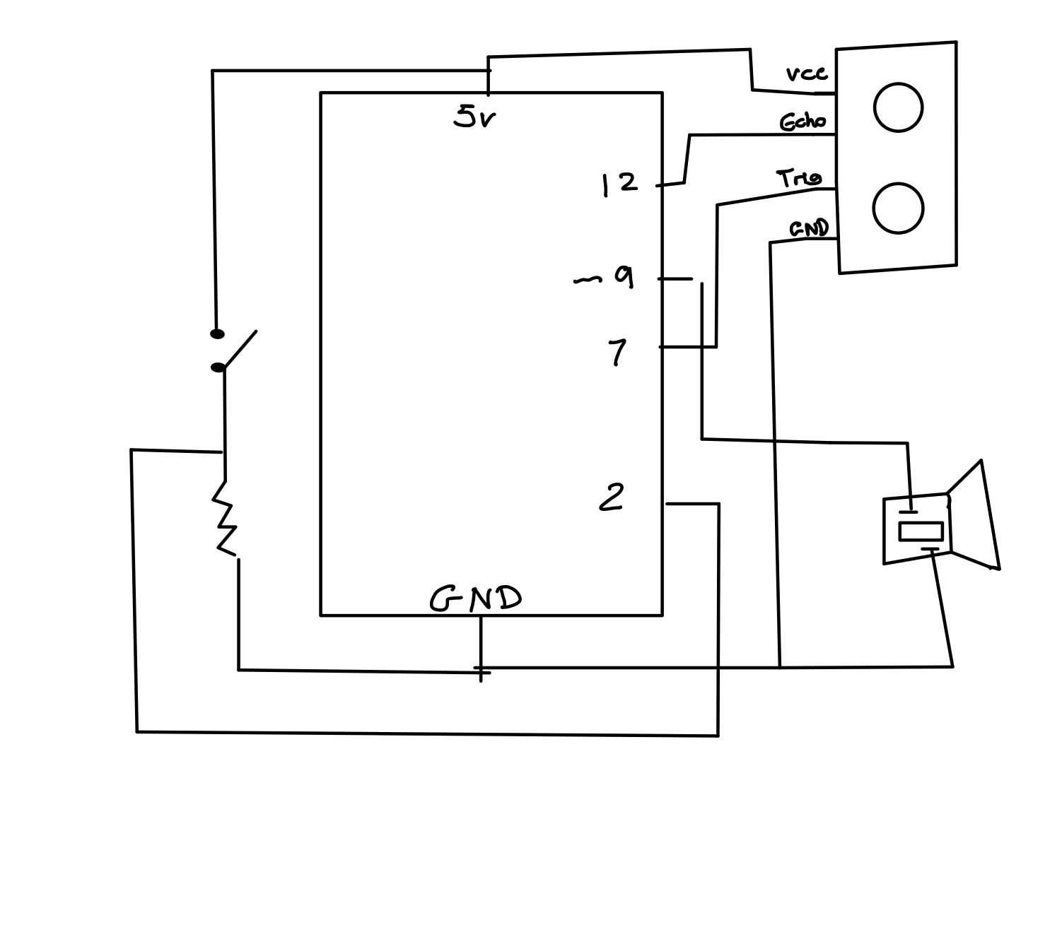
Example 1: controlling the ellipse on p5js to move horizontally by using a sensor on Arduino.

Here’s the full code that I used for p5js, which I got inspired by a YouTube tutorial that was filmed by Quarduino (link:https://www.youtube.com/watch?v=MtO1nDoM41Y). In this video I learned that I could download a third party application that was also created by p5 to access the serial port, which I downloaded from this site.

I’ve made some changes, such as playing around with whether I wanted the entire circle to be filled/just have the outer rim be filled, the size and position of the ellipse, etc. I also accidentally made the ellipse so that it shrinks/expands in size, but not actually moving, which was what the prompt was saying – so I quickly fixed my code for the ellipse to this so that I was controlling the x-axis position by the incoming data from the Arduino sensor:

ellipse(data,250,100,100);

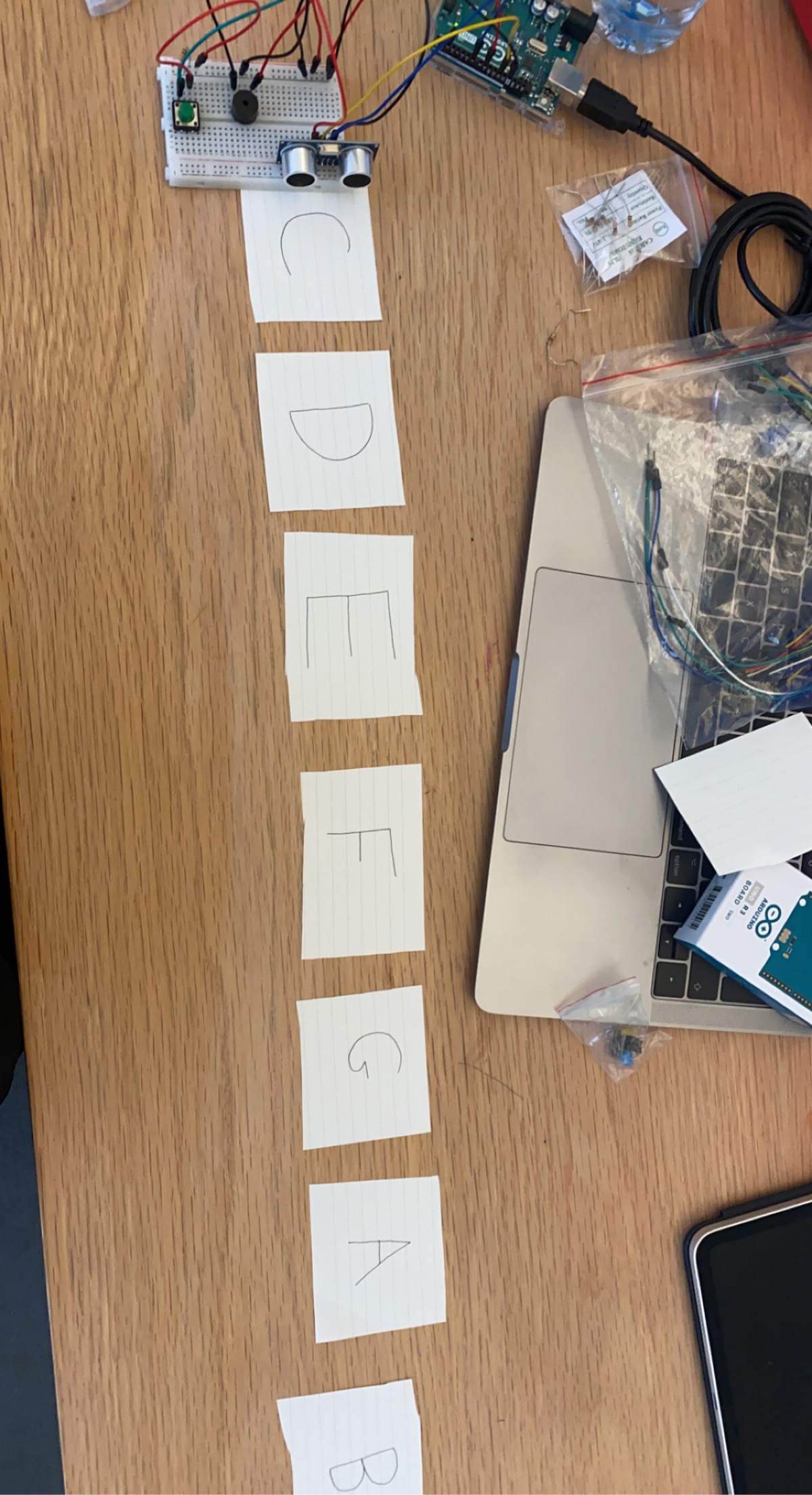
Here are the photos + video of it running:

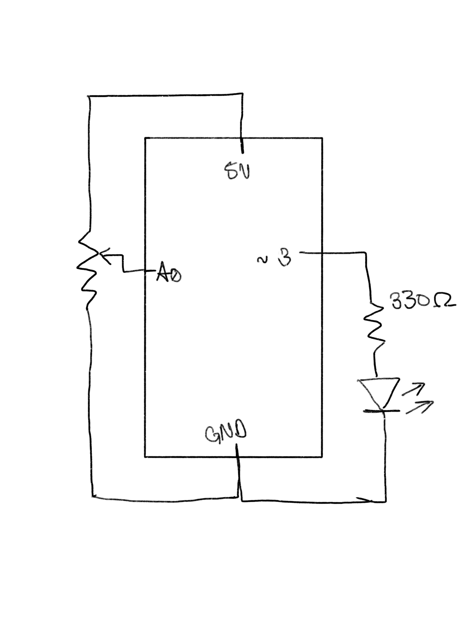
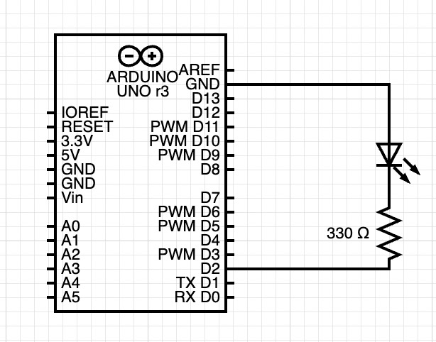
Example 2: make something that controls the LED brightness from p5

This one turned out to be the easiest one, and the most satisfying! I was suddenly inspired by the idea of “don’t press the red button” image, like the one below: Why We Always Want To Push The Big Red Button (PICTURE LINK) So I decided that I’ll create something similar in p5 so that when I press the “red button,” the red LED on the Arduino will turn on!

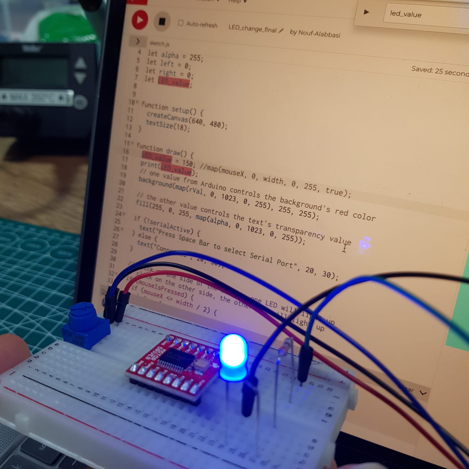
I again used the p5.serialcontrol system to connect the two, and soon I had the final result. It was a very simple circuit on the Arduino part, and the p5js coding wasn’t too difficult either, but it was really fun to create it.

Here’s the full code for p5js, and the full code for Arduino is listed here:

const int ledPin = 13;      // the pin that the LED is attached to

void setup() {
  // initialize the serial communication:
  Serial.begin(9600);
  // initialize the ledPin as an output:
  pinMode(ledPin, OUTPUT);
}

void loop() {
  int brightness;

  // check if data has been sent from the computer:
  if (Serial.available() > 0) {
    // read the most recent byte (which will be from 0 to 255):
    brightness = Serial.read();
    // set the brightness of the LED:
    analogWrite(ledPin, brightness);
  }
}

Here’s the picture and the video of it running:

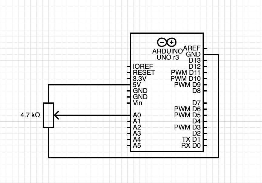
Example 3: take the gravity wind example and make it so every time the ball bounces one led lights up and then turns off, and you can control the wind from one analog sensor.

This one really took me a long, long time, and I ended up not being able to complete it. I kept getting stuck with the error message saying “TypeError: p5.SerialPort is not a constructor,” and although I discovered the problem later thanks to Professor Shiloh’s help (he said that I don’t need to access the serial port library to complete this), I ran into other problems even after removing the following code line, which was what was causing these error messages:

serial = new p5.SerialPort();

Here is the full code that I have.

I hope to finish this and crack the mystery in the near future!

Musical instrument

Concept:

For this week’s assignment, we were struggling to come up with an idea so we scouted the internet for inspiration. We came across this video https://www.youtube.com/watch?v=J8XNTHETgxU and thought it was a perfect and cool idea! The concept is essentially playing notes by moving your hands at a certain distance away from the ultrasonic sensor. The notes we used were C,D,E,F,G,A,B. The materials we needed were one breadboard, 9 wires, one ultrasonic sensor, one switch, one 10ohms resistor, and one piezo buzzer. We also placed down pieces of paper with the notes on it to help us navigate the keys.

This is an attempt at drawing the schematic:

This is what the breadboard looked like:

This is the final outcome where we played mary had a little lamb:

This is the code we are most proud of:
// plays note at a certain distance

if (distance < 0 || distance > 50 || buttonState == LOW) { //if not presed and not in front

noTone(9); //dont play music

}

else if (( buttonState == HIGH)) { //if pressed

int sound = map(distance, 0, 50, 0, 6); //map distance to the array of notes
tone(9, notes[sound]); //call a note depending on distance

}

Reflections and improvements:
Not sure if the schematic is correct. When we would reach A or B the sound would sometimes become fuzzy or cut out so it would be nice if we could fix that. It would be better if we designed our own keyboard.

Serial Communication Exercises Collaboration with Ahmed

In collaboration with Ahmed 

Exercise 1

Make something that uses only one sensor  on Arduino and makes the ellipse in p5 move on the horizontal axis, in the middle of the screen, and nothing on Arduino is controlled by p5

p5.js


Arduino

void setup() {
  Serial.begin(9600); // initialize serial communications
}
 
void loop() {
  // read the input pin:
  int potentiometer = analogRead(A0);                  
  // remap the pot value to fit in 1 byte:
  int mappedPot = map(potentiometer, 0, 1023, 0, 255);
  // print it out the serial port:
  Serial.write(mappedPot);
  //Serial.println(mappedPot);
  // slight delay to stabilize the ADC:
  delay(200);                                            
}


Exercise 2

Make something that controls the LED brightness from p5:

p5.js

Arduino

void setup() {
 Serial.begin(9600); // initialize serial communications
}
void loop() {
 if(Serial.available()) {
   digitalWrite(LED_BUILTIN, HIGH); // led on while receiving data
 
   int light = Serial.read();
   Serial.println(light);

   // the led is connected to digital pin 3 with pwm
   analogWrite(3, light);
 }                                         
}


Exercise 3

Take the gravity wind example and make it so every time the ball bounces one led lights up and then turns off, and you can control the wind from one analog sensor.

p5.js

Arduino

int potentiometer = A0;
int serialRead = 0;

void setup()
{
  Serial.begin(9600);
  pinMode(3, OUTPUT); //the led is connected to 3 pwm digital
}
 
void loop() 
{
  while (Serial.available() > 0) 
  {
    serialRead = Serial.read();
    analogWrite(3, serialRead); //the led is connected to 3 pwm digital
  }

  int mappedPotentiometer = map(analogRead(potentiometer), 0, 1023, 0, 255); 
  Serial.write(mappedPotentiometer);                                            
  delay(200);
}

Video

Abigail and Ahmed’s Week 11 Assignment: Serial Connections

//Add abigails links


For this assignment we started by building the circuit for each part and made a circuit that would work for all of them.

Circuit:


Part 1:

Link

For the first part of the assignment we took inspiration from the following website to figure out an efficient way to complete the task:

Serial Input to P5.js Using the p5.serialport library

Instead of using the potentiometer to move around an ellipse, we decided to make it move around a ufo around on a background instead:

We ran into a delay problem that would make the ufo glitch around instead of moving smoothly so we figured out the optimal delay rate:

Serial.write(mappedPot);
//Serial.println(mappedPot);
// slight delay to stabilize the ADC:
delay(200);

Also during this exercise, we started experiencing disconnection issues where the Arduino and p5js would stop communication, give erratic readings or get stuck at values (170, 20, 13, and 0). After a lot of head-scratching our fix was:

Restart the computer.

By using the mapped data received directly from the Arduino we were able to move the ufo around easily:

image(ufo, inData, 150,50,30)


Part 2:

Link

For part 2 of the assignment, we wanted to create a slider on p5js that could control the brightness of the LED as we felt it was the most intuitive way of showing light levels.

We took some coding inspiration from the following Youtube tutorial in some places:

p5.js and Arduino serial communication – control an Arduino from p5js

We made it so the slider had a length of 255 and the interval at which the bar moved was + or – 5. This allowed us to do this without including the map() function to map the values to a range of 0 to 255.

// making the slider in setup function
slider = createSlider(0, 255, 10, 5);
slider.position(50, 200);
slider.style('width', '200px');
textSize(14)
text("Use the slider to adjust brightness of the LED:", 8, 150)
outByte = slider.value()
serial.write(outByte);

Also, to make the p5js part even more interactive we added a bit of code to change the background of the canvas which made it go from a dark shade of red on lower outData() values to match the brightness of the LED.

background(outByte,0,0); 
fill(255);

On the Arduino side of things we simply used the digitalWrite() function to turn on the LED and update the output values by using the following bit of code:

   digitalWrite(LED_BUILTIN, HIGH); // led on while receiving data
 
   int light = Serial.read();
   Serial.println(light);


Part 3:

Link

For this part of the project we wanted to edit the code provided to make the ball fall slower because of air resistance but later we decided to add the sideways wind functionality because the ball was not slowing down noticeably.

For controlling the direction and magnitude of the wind we decided to use a potentiometer that was mapped to output values between 0 and 255.

int mappedPotentiometer = map(analogRead(potentiometer), 0, 1023, 0, 255); 
Serial.write(mappedPotentiometer);

The direction of the wind on either axes could be altered using the following code in p5js:

// change wind direction
windStrength = 5;
newWindDirection = map(inData, 0, 255, -windStrength, windStrength);
wind.y = newWindDirection;  // make ball fall slower
wind.x = newWindDirection;  // make ball move on the horizontal axis

We noticed that there was a delay between the ball hitting and the LED on the circuit lighting up so we made the background change colors every time the ball hit the bottom of the screen to give us visual feedback of what we were looking at:

background(backgroundShade, 0, 10);

//where the value of backgroundShade updates everytime the ball hits the ground using //the following bit of code:
// if (positionOfBall.y > height - mass/2 - mass) {
//backgroundShade = backgroundShade + 5
//}

Video:

Serial Communication Assignments

Task 1:

  1. make something that uses only one sensor  on arduino and makes the ellipse in p5 move on the horizontal axis, in the middle of the screen, and nothing on arduino is controlled by p5

    To do this assignment, I used a potentiometer that is connected to pin A0, and was reading from the potentiometer and using the result to control the xPosition of the ellipse. I mapped the values from 0, 1023 to become from 0,width of the p5 screen to have good results. Here is the code that I used for the assignment

    let ellipseXPos=100;
    
    function setup() {
      createCanvas(640, 480);
      textSize(18);
    }
    
    function draw() {
      // one value from Arduino controls the background's red color
      background(104, 255, 255);
      map(ellipseXPos,0,1023,0,width);
      ellipse(ellipseXPos,height/2,100,50);


      // the other value controls the text's transparency value
     
    
      if (!serialActive) {
        text("Press Space Bar to select Serial Port", 20, 30);
      } else {
        text("Connected", 20, 30);
      }
    
      // click on one side of the screen, one LED will light up
      // click on the other side, the other LED will light up
      
    }
    
    function keyPressed() {
      if (key == " ") {
        // important to have in order to start the serial connection!!
        setUpSerial();
      }
    }
    
    function readSerial(data) {
      ////////////////////////////////////
      //READ FROM ARDUINO HERE
      ////////////////////////////////////
    
      if (data != null) {
        ellipseXPos=data;
        }
    
      
    }
    
    //Arudino Code
    /*
    void setup() {
      Serial.begin(9600);
    }
    
    void loop() {
      // wait for data from p5 before doing something


          int sensor = analogRead(A0);
          delay(1);
          Serial.println(sensor);
        
      
    }
    */
    

    Task 2

  2. make something that controls the LED brightness from p5
    To do this task I decided to use the up and down arrows to control the brightness of the LED from p5. However, I spent so much time doing this because I was not able to setup the communication between arduino and p5 correctly. However, I was inspired by how other people did it and finally figured out how to do it. Here is part of the code

    function keyPressed() {
      if (key == " ") {
        // important to have in order to start the serial connection!!
        setUpSerial();
      }
      if(keyCode==UP_ARROW){
        val+=50;
      }
      if(keyCode==DOWN_ARROW){
        val-=50;
      }
    }
    function readSerial(data) {
      ////////////////////////////////////
      //READ FROM ARDUINO HERE
      ////////////////////////////////////
      
      if (data != null) {
        // if there is a message from Arduino, continue
        //////////////////////////////////
        //SEND TO ARDUINO HERE (handshake)
        //////////////////////////////////
        let sendToArduino = brightness + "\n";
        writeSerial(sendToArduino);
      }
    }
    
    // int LED = 3;
    // void setup() {
    //   Serial.begin(9600);
    //   pinMode(LED, OUTPUT);
    //   // start the handshake
    //   while (Serial.available() <= 0) {
    //     Serial.println("Wait");  // send a starting message
    //     delay(300);               // wait 1/3 second
    //   }
    // }
    // void loop() {
    //   // wait for data from p5 before doing something
    //   while (Serial.available()) {
    //     int brightness = Serial.parseInt(); 
    //     if (Serial.read() == '\n') {
    //       analogWrite(LED, brightness); // turn on LED and adjusts brightness
    //       Serial.println("Light is ON"); 
    //     }
    //   }
    // }


Task 3:

For this task I used the gravity wind example to come up with a code that lights up the LED when the ball is bouncing, also I used a potentiometer to control the wind speed as seen in this part of the code.

if (position.y > height-mass/2) {
      velocity.y *= -0.9;  // A little dampening when hitting the bottom
      position.y = height-mass/2;
      LEDbrightness=1;
      
    
    }
  else{
  LEDbrightness=0;
  }
  if(windSpeed<500){
  wind.x=-1;
  }
  else if(windSpeed>700){
    wind.x=1;
  }
  else{
    wind.x=0;
  }

Here is a video that shows how the code above works:

Nouf&Zhaniya exercises

Task 1

For the first task, we used potentiometer on our circuit and controlled the X_pos of an ellipse in p5js. We also set up a port choosing thing, so the code requested port connection every time we start the program.
Link to our full code:
https://editor.p5js.org/Zhaniya/full/ft2iMvilF


Circuit:

result:

Task 2

We used aaron sherwood’s code code which sends and receive data to the arduino. We tried to move those two lines of code

let sendToArduino = LED_value + "\n";
writeSerial(sendToArduino);

In the draw function instead of the readSerial() function, but that resulted in a errors with the writeSerial function. We also tried to remove the code in the readSerial function that waits for input from the arduino before sending anything while keeping the two lines of code where it originally is, but that wasn’t working either. We ended up using the original code, but we sent random values to p5js from the arduino and sending the LED brightness value (which is based on where the mouse is horizontally) to the arduino.

LED_value = map(mouseX, 0, width, 0, 255, true);
print(LED_value);

Here is a link to the code: https://editor.p5js.org/Nouf-Alabbasi/sketches/gJtQGnh0w

circuit:

the video below shows the LED reacting to the mouse movement (the first video shows the LED and the second Shows the mouse moving)


Task 3

For the third exercise we followed similar to exercise 2 steps to complete it. We used with gravity wind example with bouncing ball (https://editor.p5js.org/aaronsherwood/sketches/I7iQrNCull) to send the data to the Arduino. After that, we initialized LED_value and set up serial connection.

Code:
https://editor.p5js.org/Nouf-Alabbasi/sketches/Eq7USk-wJ


circuit:

Problems that we faced:

Some of the problems we faced were simply fixed by uploading the code to the arduino microcontroller but others were a little more challenging to fix. One thing that was not going the way we expected was the LED not gradually changing from one value to another. It seemed to jump from on to off which is not what we were going for.
Here is the p5js code:

// define the LED brightness as the mouse movement
LED_value = map(mouseX, 0, width, 0, 255, true);
print(LED_value);
…
let sendToArduino = LED_value + "\n";
writeSerial(sendToArduino);

And here is the Arduino code:

…
int LED_val = Serial.parseInt();
if (Serial.read() == '\n') {
analogWrite(2, LED_val);
…

One hypothesis is perhaps parseInt doesn’t handle decimals in numbers, so we expect that it might’ve stopped at the first part of the decimal before the decimal. The numbers should still be usable though, so this doesn’t fully explain why the LED wasn’t being controlled in the way we wanted. (After searching online we found that using parseFloat would be a better fit for our code.

Serial Communication – Nouf and Zhaniya

Task 1

For the first task, we used potentiometer on our circuit and controlled the X_pos of an ellipse in p5js. We also set up a port choosing thing, so the code requested port connection every time we start the program.
Link to our full code:
https://editor.p5js.org/Zhaniya/full/ft2iMvilF


Circuit:

result:

Task 2

We used aaron sherwood’s code code which sends and receive data to the arduino. We tried to move those two lines of code

let sendToArduino = LED_value + "\n";
writeSerial(sendToArduino);

In the draw function instead of the readSerial() function, but that resulted in a errors with the writeSerial function. We also tried to remove the code in the readSerial function that waits for input from the arduino before sending anything while keeping the two lines of code where it originally is, but that wasn’t working either. We ended up using the original code, but we sent random values to p5js from the arduino and sending the LED brightness value (which is based on where the mouse is horizontally) to the arduino.

LED_value = map(mouseX, 0, width, 0, 255, true);
print(LED_value);

Here is a link to the code: https://editor.p5js.org/Nouf-Alabbasi/sketches/gJtQGnh0w

circuit:

the video below shows the LED reacting to the mouse movement (the first video shows the LED and the second Shows the mouse moving)


Task 3

For the third exercise we followed similar to exercise 2 steps to complete it. We used with gravity wind example with bouncing ball (https://editor.p5js.org/aaronsherwood/sketches/I7iQrNCull) to send the data to the Arduino. After that, we initialized LED_value and set up serial connection.

Code:
https://editor.p5js.org/Nouf-Alabbasi/sketches/Eq7USk-wJ


circuit:

Problems that we faced:

Some of the problems we faced were simply fixed by uploading the code to the arduino microcontroller but others were a little more challenging to fix. One thing that was not going the way we expected was the LED not gradually changing from one value to another. It seemed to jump from on to off which is not what we were going for.
Here is the p5js code:

// define the LED brightness as the mouse movement
LED_value = map(mouseX, 0, width, 0, 255, true);
print(LED_value);
…
let sendToArduino = LED_value + "\n";
writeSerial(sendToArduino);

And here is the Arduino code:

…
int LED_val = Serial.parseInt();
if (Serial.read() == '\n') {
analogWrite(2, LED_val);
…

One hypothesis is perhaps parseInt doesn’t handle decimals in numbers, so we expect that it might’ve stopped at the first part of the decimal before the decimal. The numbers should still be usable though, so this doesn’t fully explain why the LED wasn’t being controlled in the way we wanted. (After searching online we found that using parseFloat would be a better fit for our code.

Aisha – Ball Run Game Final Project Concept

For my final project, I want to create a 3d type of game where the ball has to jump on obstacles. The further you get the higher your score will be similar to subway surfer. To make it physically interactive, I want to have the Arduino connected to a glove so the user can move/tilt their hands to guide the ball onto the obstacle. If this doesn’t work I will use buttons to move left/right and jump. Once the ball falls a game-over screen will be displayed with the user’s score, high score, and option to restart the game.

Assignment 8: Serial Communication

Group: Aisha, Hessa, Joonha

Schematics includes all three exercises:

Exercise 1:

Arduino Code (Credit to Hessa):

void setup() {
  Serial.begin(9600); // initialize serial communications
}
 
void loop() {
  // read the input pin:
  int potentiometer = analogRead(A0);                  
  // remap the pot value to fit in 1 byte:
  int mappedPot = map(potentiometer, 0, 1023, 0, 255);
  // print it out the serial port:
  Serial.write(mappedPot);
  //Serial.println(mappedPot);
  // slight delay to stabilize the ADC:
  delay(1);                                            
}

p5js:


Exercise 2:

Arduino Code (Credit to Aisha):

int LED = 5;
void setup() {
  Serial.begin(9600);
  pinMode(LED, OUTPUT);
  // start the handshake
  while (Serial.available() <= 0) {
    Serial.println("Wait");  // send a starting message
    delay(300);               // wait 1/3 second
  }
}
void loop() {
  // wait for data from p5 before doing something
  while (Serial.available()) {
    int brightness = Serial.parseInt(); 
    if (Serial.read() == '\n') {
      analogWrite(LED, brightness); // turn on LED and adjusts brightness
      Serial.println("LIT"); 
    }
  }
}

p5js:

Working Video:


Exercise 3:

Arduino Included in the p5sketch (Credit to Joonha)


Working Video:

Abigail and Ahmed’s Final Project IDea

Interactive Artwork: Fern Plant Robot Instrument Thing


So for our project, we wanted to do something artistic. The idea we have, came from the following piece of computer graphic art:

Interactive Walls

The artwork is graphic and based around Max but we thought it would look really great if implemented in real life with servo motors and multicolored panels.

The panels will be mounted to servo motors and be multicolored to look aesthetically pleasing. The panels can be made out of acrylic material or something lighter like thin plywood or cardboard. Due to restrictions of the Arduino Uno, we will only be able to use a maximum of 12 panels for our interactive artwork.


Functionality:

We want the panels to depict a living, breathing, organism that reacts to different inputs; touch, noise, and input controls on a mounted panel. The artwork itself will have two speakers that will create a surround sound effect and can also output predetermined responses to different stimuli.

The control panel for the artwork will have a few buttons that will change modes. Modes can be an ambient mode that makes predetermined patterns, music mode which will make the artwork react to music playing, and a touch mode that will allow the audience to touch the artwork and have it react to their inputs.

The whole piece can be controlled by a single Arduino which will be responsible for the servo motors. For the buttons and knobs, we don’t think there will be enough I/O options on the Arduino Uno to make everything work so we will use a touchscreen with a p5js program to make digital buttons.

Concept Image:


Additional Information:

  1. The speaker chamber behind the art piece
  2. The initial look of the moving panels

We also found the following code that may help us during the production of this project:

Audio Reactive Program