All Posts

WEEK 9 RED LIGHT GREEN LIGHT


IMG_3777

Concept:

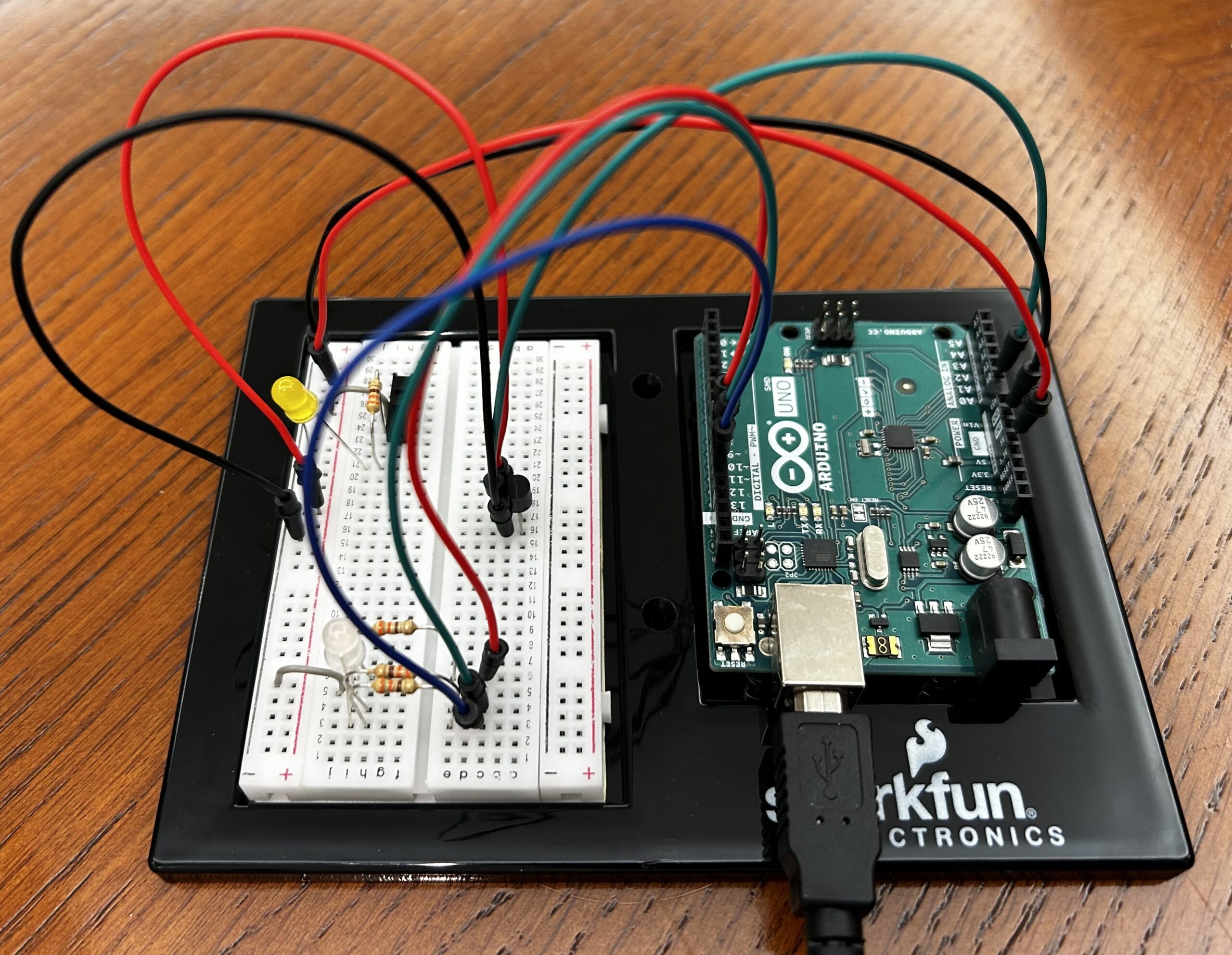
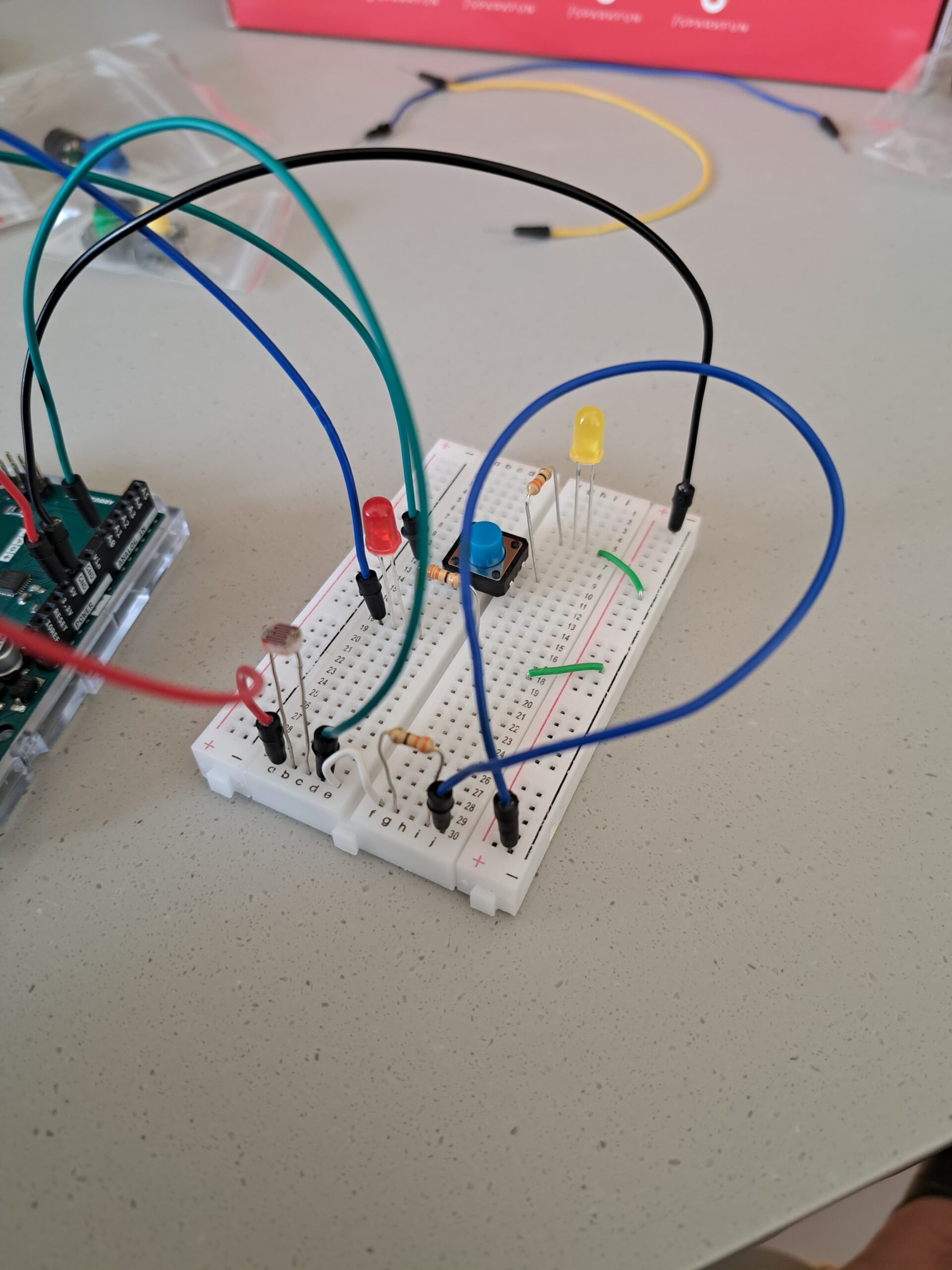
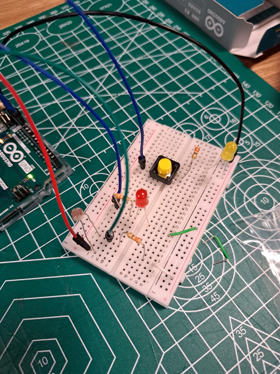
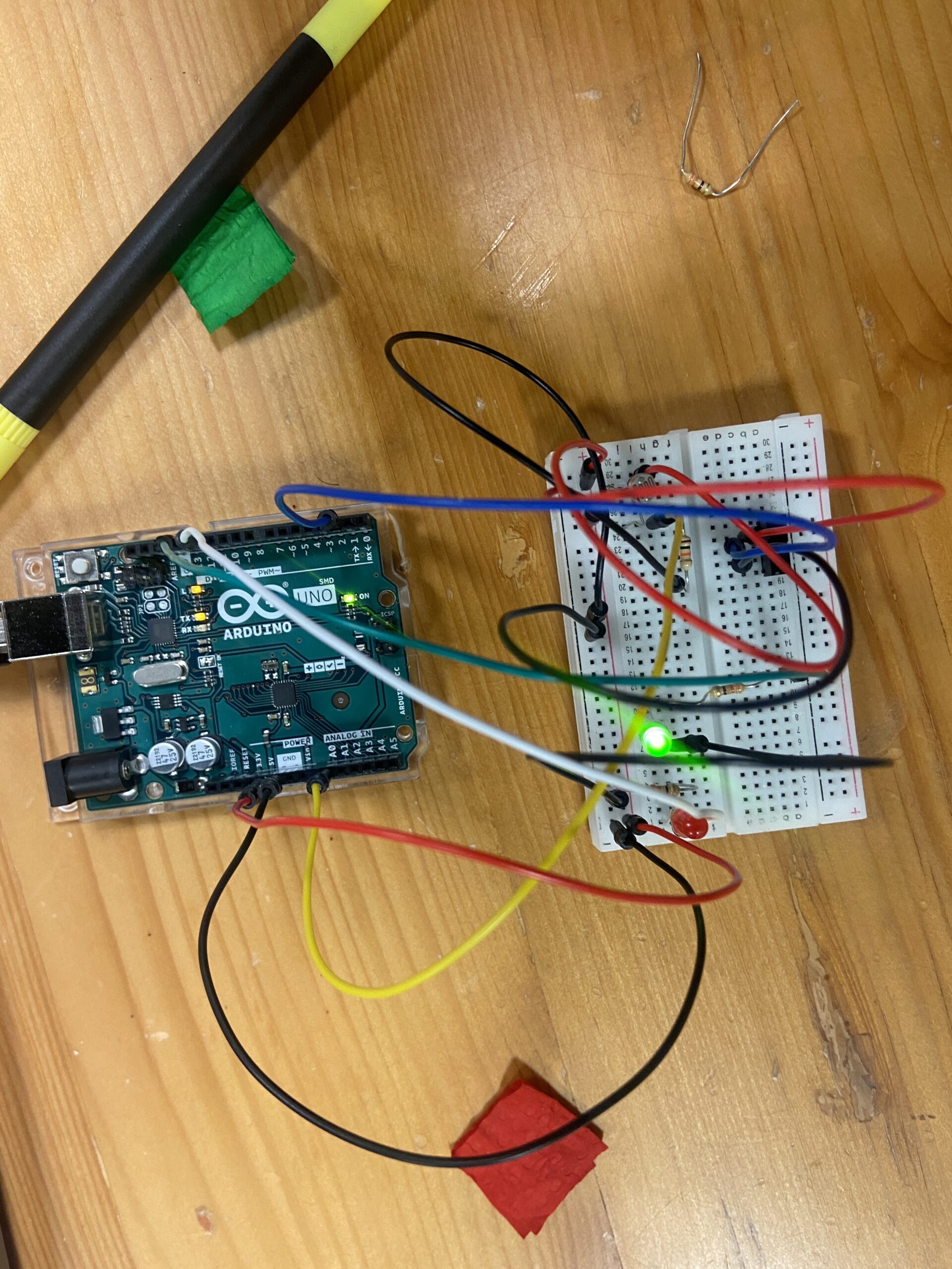
For this project, I wanted to re-create a stop light or intersection, where a “car” could be driving when the light is green and a pedestrian could press a button to turn the traffic light red, so that they could walk and cars could not drive forward. I really liked this concept, because it reminded of all the times I would be walking by an intersection and would attempt to press the button to turn the traffic light red and it would never work.  With this model, the light actually turn red to let the pedestrians cross.

FUN FACT: I made the car a Tesla, because I really like teslas.  (:

// Set pin names
// to keep track of what is connected to which pin, we set global variables that name each pin
// this also allows us to use these names in functions like "pinMode" & "digitalWrite" instead of the pin numbers. 
const int switch_Pin = 2;
const int lightSensor_Pin = A0;
const int LED_green = 13;
const int LED_red = 12;
void setup() {

  //Start the serial monitor
 Serial.begin(9600);
 //Set pin modes
 // The LED pins are OUTPUT pins because we are sending information to the LED instead of receiving information from it
 // the information we are sending is in the form of HIGH or LOW
 // this is an alternative to connecting the LED lights straight to the 5V pin, which constantly outputs 5 volts
 // with these pins being used as OUTPUTs we can control wether the LED is recieving power or not.
 pinMode(LED_green, OUTPUT);
 pinMode(LED_red, OUTPUT);

 // The switch pin is an INPUT pin because we are taking in information from the switch about whether it is ON or OFF.
 pinMode(switch_Pin,INPUT);
}

void loop() {
  // Set variables for the input from the light sensor & the switch
  
  // for the lightValue variable, we want it to be equal to the value coming from the light sensor
  // the data coming form the sensor is analog data so we use the "analogRead()" function and we give it the pin it's supposed to read from
  // here we give it the pin connected to the light sensor (A0)

   int lightValue = analogRead(lightSensor_Pin);

  // for the switchState variable, we want it to be equal to the value coming from the switch
  // the data coming form the switch is digital (either HIGH or LOW) so we use the "digitalRead()" function and we give it the pin it's supposed to read from
  // here we give it the pin connected to the switch (2)

   int switchState = digitalRead(switch_Pin);

   // Prints values from sensor in serial monitor
   // we use the "Serial.print()" function to send information serial monitor (open using bottom on top right) so that we can read it
   Serial.print("Analog reading: ");
   Serial.print(lightValue);
   // "\n" is a line break, makes the serial monitor start on a new line
   Serial.print("\n");

// If statement to check if there is something blocking the light from the light sensor & control the green LED accordingly
// if the value coming form the light sensor is less than 700,
   if (lightValue < 800) {
    // we use the "digitalWrite()" to send data to the green LED, in this case we send "HIGH" so that it turns on
    digitalWrite(LED_green,HIGH);
    // else ; if the light value is not less than 700
   } else {
    // we send a "LOW to the green LED so that it turns off"
    digitalWrite(LED_green,LOW);
   }
  
  // If statement to check if the switch is ON or OFF & controls the red LED light accordingly 
  if (switchState == HIGH){
    digitalWrite(LED_red,HIGH);
    digitalWrite(LED_green,LOW);
  } else if (switchState == LOW){
    digitalWrite(LED_red,LOW);
  }
  

}


Week 9- Sunset Effect

Concept:

The concept involves creating an Arduino-based project that combines analog and digital sensors to control two LEDs in a creative way.  The goal is to simulate a sunset effect using the LDR to detect ambient light levels. The system uses the button to sequentially turn on two LEDs and the potentiometer to adjust the brightness, providing a visually appealing sunset simulation.

Sunset Simulation Sequence:

    1. Initialization:
      • Upon activation, both yellow and red LEDs light up simultaneously, representing the starting point of the sunset effect.
    2. First Button Press:
      • When the button is pressed for the first time, the yellow LED dims or turns off, symbolizing the initial phase of the sunset where daylight begins to fade.
    3. Second Button Press:
      • Upon another press of the button, the red LED dims or turns off, indicating the advanced stage of the sunset where the sky adopts warmer hues.
    4. Potentiometer Control:
      • Throughout the simulation, the potentiometer allows users to adjust the overall brightness, offering a real-time customization of the sunset effect.

https://youtu.be/DqOrlSnHzus

Code: 

const int buttonPin = 2;     // Pin number for the push button (connected to ground with pull-up resistor)
const int led1Pin = 3;       // Pin number for the first LED
const int led2Pin = 5;       // Pin number for the second LED
const int potPin = A0;       // Pin number for the potentiometer

int buttonState = HIGH;      // Variable to store the current state of the button
int lastButtonState = HIGH;  // Variable to store the previous state of the button
int led1State = LOW;         // Variable to store the state of the first LED
int led2State = LOW;         // Variable to store the state of the second LED
int potValue = 0;            // Variable to store the potentiometer value
int brightness = 0;          // Variable to store the LED brightness
int flag = 0;

void setup() {
  pinMode(buttonPin, INPUT_PULLUP);
  pinMode(led1Pin, OUTPUT);
  pinMode(led2Pin, OUTPUT);
}

void loop() {
  buttonState = digitalRead(buttonPin);

  // Check if the button is pressed (LOW) and was not pressed before
  if (buttonState == LOW && lastButtonState == HIGH) {
    // Toggle the state of the first LED
    led1State = !led1State;
    digitalWrite(led1Pin, led1State);

    // If the first LED is turned on, wait for the second button press to turn on the second LED
    if (led1State == HIGH) {
      delay(50); // Debounce delay
      buttonState = digitalRead(buttonPin);
      if (buttonState == LOW) {
        // Toggle the state of the second LED
        led2State = !led2State;
        digitalWrite(led2Pin, led2State);
        flag = 1;
      }
    }
  }

  if (flag == 1) {
    // Read the potentiometer value and map it to the LED brightness range (0-255)
    potValue = analogRead(potPin);
    brightness = map(potValue, 0, 1023, 0, 255);

    // Apply the brightness to both LEDs
    analogWrite(led1Pin, led1State ? brightness : 0);
    analogWrite(led2Pin, led2State ? brightness : 0);
  }

  // Save the current button state for the next iteration
  lastButtonState = buttonState;
}


Improvements:

For future upgrades, I want to make the lights in my project more interesting by creating complex patterns. I’m thinking of making the sunset simulation more dynamic and captivating with intricate lighting sequences inspired by nature. Also, I’d like to get better at drawing schematics.

Week 9 – Assignment – Caution Coaster

For this assignment we were required to apply the concepts and components used so far to create a project involving an analog sensor, a digital sensor and two LEDs. I decided to explore the functioning of the TMP36 Temperature sensor and have used it as the analog sensor to develop a simple temperature detection model that may be employed in beverage holders to warn the people of the temperature of the contents of the glass.

Using the RGB LED, I have depicted temperature ranges from hot to cold by changing the colors from red to green to blue. Apart from this I have used a switch along with a yellow LED which may be turned on or off. As the program runs, the corresponding temperature value is printed in the Serial Monitor.

I have demonstrated the working of this circuit using glasses containing water of different temperatures ranging from ice cold to boiling hot and was able to achieve the desired color code.

Assignment Video

I particularly enjoyed figuring out the connections and coding for the temperature sensor through a video and the datasheet provided.

Overall, I believe the assignment helped me delve deeper into creating simple circuits and the commands of Arduino IDE.

int RED=9;
int GREEN=10;
int BLUE=11;
int PIN=A0;
void setup() {
  Serial.begin(9600);
  pinMode(RED,OUTPUT);
  pinMode(BLUE,OUTPUT);
  pinMode(GREEN,OUTPUT);
}

void loop() {
  int sensorValue=analogRead(PIN);
  delay(200); //delays the frequency of temperature readings
  float mv = sensorValue*4.9; //converts the analog input into mV
  float temp = (mv-500)/10; //calculates the final temperature value
  Serial.print("Temperature: ");
  Serial.print((mv-500)/10);
  Serial.print("°C\n");
  if (temp>27){
    digitalWrite(RED,HIGH);
    digitalWrite(GREEN,LOW);
    digitalWrite(BLUE,LOW);
  }
  else if (temp>21){
    digitalWrite(GREEN,HIGH);
    digitalWrite(RED,LOW);
    digitalWrite(BLUE,LOW);
  }
  else if (temp>16){
    digitalWrite(BLUE,HIGH);
    digitalWrite(GREEN,LOW);
    digitalWrite(RED,LOW);
  }
  
}


Week 9 – Reading Reflection

In this week’s reading, “Making Interactive Art: Set the Stage, Then Shut Up and Listen” the author set out the fundamental nature of interactive art as free and uncontrolling. He argues that artists should never impose or provide their intentions or interpretation of the artwork to the viewer. This field of art calls for the complex nature of human thought to allow the viewer to explore unique interpretations impacted by personal experiences. I found this idea to be particularly relatable as I often witness people having entirely different viewpoints regarding pieces of art. I also feel that if an artist provides their interpretation or explanation, it limits the viewer from exploring their thoughts as they begin to believe that there is only one right understanding of the art. Providing viewers with the freedom to think brings out their true reaction and adds greater depth to the interactive art. It may also be possible for the artist to discover a new dimension of their own work which they may not have previously considered. Hence, I completely agree with the argument presented by the author and firmly believe that the world of interactive art is all about exploring yourself through the displays.

The second reading, “Physical Computing’s Greatest Hits (and misses)”, felt like an unexplored world of opportunities. I was intrigued to read about the numerous projects created using various aspects of physical computing. It has also provided with an inspiration to think more creatively for future assignments. It was interesting to note that all involved relatively similar components and yet were so diverse in concept and implementation.

Reflection:

Blending the two ideas, Tigoe is like, “Why stick to the same old system when we can spice it up?” Even if it’s another dance floor pad or a gesture-controlled gadget, there’s a whole treasure trove of learning. It’s about giving users the stage to express themselves through art. Creators should give room to users to play and explore, setting up a playground for artistic talents. It’s like peeking into people’s thoughts, adding value to your creation by tuning in to their reactions. All in all, artwork should allow us the viewers or listeners to know the inner thoughts of the viewer to which their reaction was used to create the artwork as well as the designer that made the platform. This is one main thing I resonated with. After all isn’t that what interactive media is?

Week 9- Reflection

The text emphasizes the delicate balance in creating interactive art, cautioning against excessive interpretation. The author challenges the conventional idea that art is a fixed statement, urging artists to view interactive works as ongoing conversations with the audience. This perspective aligns interactive art more with directing a performance than crafting a traditional piece. By providing a basic context, then allowing the audience to navigate and interpret, without imposing predefined meanings. The analogy to directing actors underscores the importance of enabling discovery rather than dictating emotions. It encourages artists to see their creations not as finished products but as evolving performances, completed by the audience’s engagement. It invites a shift from dictation to collaboration, where the audience becomes an integral part of the artistic process.

With the given examples in the text “Physical Computing’s Greatest Hits (and misses)”, it is beautifully shown how these ideas are developed within ourselves based on creativity and sense of living. As an artists I love to add small touches on things I leave behind. It is nice to look back upon them one day and maybe add more bits of the journey beyond that point. The things we create aren’t necessarily useful or practical, but it’s something that allows us to project oursleves freely and openly.

Just Work

Concept

For this particular assignment, I didn’t particularly aim for anything. I have been having issues with connecting some of the components of the arduino kit and getting them to work so I decided to strictly get stuff to work. I utilized three buttons, jumper wires, three LEDs, a potentiometer, and the arduino UNO board. Using the value read from the potentiometer as a delay time, the LEDs are blinked using different buttons. That’s basically what the setup does.

I’ve included the sketch below.

//set the pins for the button and leds
int firstKeyPin = 2;
int secondKeyPin = 3;
int thirdKeyPin = 4;

int led1 = 9;
int led2 = 10;
int led3 = 11;

void setup() {
  //set the button pins as inputs
  pinMode(firstKeyPin, INPUT_PULLUP);
  pinMode(secondKeyPin, INPUT_PULLUP);
  pinMode(thirdKeyPin, INPUT_PULLUP);

  // set leds for output
  pinMode(led1, OUTPUT);
  pinMode(led2, OUTPUT);
  pinMode(led3, OUTPUT);

}

void loop() {
  // read voltage from potentiometer
  int delay_time = analogRead(A0);

  if(digitalRead(firstKeyPin) == LOW){        //if the first key is pressed
    // turns on led1
    digitalWrite(led1, HIGH);
    // delays for the value read from the potentiometer
    delay(delay_time);
    // turns off led1
    digitalWrite(led1, LOW);
    // delays for the value read from the potentiometer
    delay(delay_time);
  }
  else if(digitalRead(secondKeyPin) == LOW){  //if the second key is pressed
    // turns on led2
    digitalWrite(led2, HIGH);
    // delays for the value read from the potentiometer
    delay(delay_time);
    // turns off led2
    digitalWrite(led2, LOW);
    // delays for the value read from the potentiometer
    delay(delay_time);
  }
  else if(digitalRead(thirdKeyPin) == LOW){   //if the third key is pressed
    // turns on led3
    digitalWrite(led3, HIGH);
    // delays for the value read from the potentiometer
    delay(delay_time);
    // turns off led3
    digitalWrite(led3, LOW);
    // delays for the value read from the potentiometer
    delay(delay_time);
  }
  else{
    // turns off all leds
    digitalWrite(led1, LOW);
    digitalWrite(led2, LOW);
    digitalWrite(led3, LOW);
  }
}

Ideas for Future Improvements

For future improvements, I hope it doesn’t take me as much time as it took me this time to get everything working properly.

I used the tinker kit circuit guide as a reference when I got stuck.

Reading Reflection – Week 9

In my initial perspective, I approached the interaction in physical computing from a strictly practical standpoint. However, the revelation brought about by the mechanical pixels and the surrounding fields of grass has broadened my understanding, highlighting the potential for creativity and aesthetics in these interactions. Previously, I considered the user’s input as the primary influence, shaping the device’s responses accordingly. Yet, the mechanical pixels and the grassy environment exhibit a distinct “will of technology.” Despite their simplicity, they engage with their surroundings not merely to fulfill a predetermined purpose dictated by humans, but to actively create an interaction with people. An illustrative example is the subtle quivering of the mechanical pixel “leaves” in an attempt to attract attention when no one is nearby. As individuals pass by, they collectively form a wave, accompanied by a tinkling sound, showcasing a dynamic and engaging interaction that transcends the conventional user-device relationship.

After delving into Tigoe’s “Making Interactive Art,” my perspective on interaction and interactivity has evolved. Initially, I conceived these concepts as a straightforward exchange where two entities respond to each other through inputs and outputs. However, Tigoe’s insights have led me to perceive interactivity as a more nuanced and profound experience. The excerpt from “Making Interactive Art” that resonated with me emphasizes the importance of letting the audience absorb the work through their senses, encouraging them to contemplate the meaning of each part, identify elements open to contact or control, and ultimately empowering them to interpret and respond in their own unique ways.

This perspective reframes interactivity as a process that places emphasis on the receiving end, highlighting the significance of allowing individuals to engage with artistic or interactive creations on a personal and subjective level. Rather than a uniform response to inputs, true interactivity, as suggested by Tigoe, enables a diverse range of interpretations and responses. In this light, I now see interaction not only as a means of communication but also as a pathway for individuals to feel a sense of uniqueness, care, and individuality within the realm of human experience.

Financial Management

So uhhh… I bought… A desk lamp… For a hundred dirhams. A hundred. A hundred as in 1-0-0.

Impulsive purchases got the best of me again.

Anyways, I decided I would use this lamp for something other than playing around with its colors. So I made this kind of proximity/light sensor thing. Basically when I hold the lamp close to the the circuit, the red LED turns off and as I back up the lamp, the red LED blinks slower and slower until it stops blinking. As long as the red LED blinks/is on, the green LED can be turned on using a digital switch. Initially while making this circuit, I ran into some very silly difficulties – I attached the components on a single row which meant the circuit was never complete and I couldn’t figure out the problem the entire night for the life of me. Here is the bad circuit:

But one debugging session later here is my creation, the good circuit:

It works in a very fun way and the lamp works in an even fun-er way. Check out the video I’ve attached of the LEDs in action:

https://drive.google.com/drive/folders/1uOQwTJqiPt6b5cQ-L8GTVn3CXHp50x17?usp=sharing

Here is the code:

int green = 10;
int red = 11;
// the setup routine runs once when you press reset:
void setup() {
  // initialize serial communication at 9600 bits per second:
  Serial.begin(9600);
  pinMode(green, OUTPUT);
  pinMode(red, OUTPUT);
}

// the loop routine runs over and over again forever:
void loop() {
  // read the input on analog pin 0:
  int sensorValue = analogRead(A0);
  // print out the value you read:
  Serial.println(sensorValue);
  delay(1);  // delay in between reads for stability

if (sensorValue > 40) { // when far, turn on but don't blink
  digitalWrite(green, LOW);
  digitalWrite(red, LOW);
}
if (sensorValue > 15 && sensorValue <= 40) { // when slightly close, blink slow
  digitalWrite(green, HIGH);
  digitalWrite(red, HIGH);
  delay(100);
  digitalWrite(red, LOW);
  delay(100);
}
if (sensorValue <= 15 && sensorValue > 10) { // when closer, blink fast
  digitalWrite(green, HIGH);
  digitalWrite(red, HIGH);
  delay(250);
  digitalWrite(red, LOW);
  delay(250);
} 
if (sensorValue <= 10) { // when very close, turn off
  digitalWrite(green, HIGH);
  digitalWrite(red, HIGH);
}  

}