function draw() {
  background(250, 200, 152);

  if (!serialActive) {
    print("Press Space Bar to select Serial Port");
  } else {
    print("Connected");

    brightness = Math.floor(map(rVal, 0, 1023, 0,255));
    right = Math.floor(brightness);
  }
}
The only change in Arduino code I made was using analogWrite instead of digitalWrite.
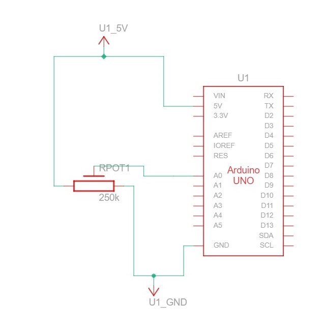
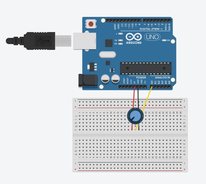
Make something that uses only one sensor on Arduino and makes the ellipse in p5 move on the horizontal axis, in the middle of the screen, and nothing on Arduino is controlled by p5.
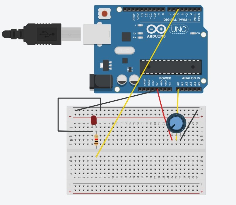
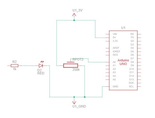
SCHEMATIC AND MODELLING:
P5 CODE:
let circleX = 0;
function setup() {
  createCanvas(640, 480);
  textSize(18);
}

function draw() {
  background(255);
  stroke(0);

  fill("pink");
  circle(map(circleX,0, 1023, 0, width), height/2, 50);

  if (!serialActive) {
    text("Press Space Bar to select Serial Port", 20, 30);
  } else {
    text("Connected", 20, 30);
  }

}

function keyPressed() {
  if (key == " ") {
    // important to have in order to start the serial connection!!
    setUpSerial();
  }
}

// This function will be called by the web-serial library
// with each new *line* of data. The serial library reads
// the data until the newline and then gives it to us through
// this callback function
function readSerial(data) {
  ////////////////////////////////////
  //READ FROM ARDUINO HERE
  ////////////////////////////////////

  if (data != null) {
    circleX = int(trim(data));

  }
  print(circleX);
}
ARDUINO CODE:
void setup() {
  // Start serial communication so we can send data
  // over the USB connection to our p5js sketch
  Serial.begin(9600);

  // We'll use the builtin LED as a status output.
  // We can't use the serial monitor since the serial connection is
  // used to communicate to p5js and only one application on the computer
  // can use a serial port at once.
  pinMode(LED_BUILTIN, OUTPUT);

}

void loop() {

  int sensor = analogRead(A0);
  delay(5);
  digitalWrite(LED_BUILTIN, HIGH);
  Serial.println(sensor);

  digitalWrite(LED_BUILTIN,LOW);
}
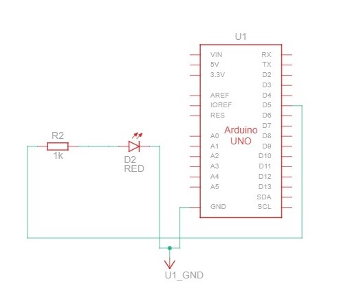
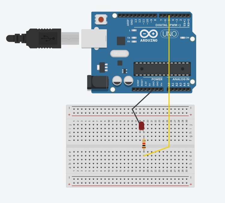
Make something that controls the LED brightness from p5.
SCHEMATIC AND MODELLING:
P5 CODE:
let value = 0;

function setup() {
  createCanvas(640, 480);
  textSize(18);
}

function draw() {
  background(0);
  stroke(255);
  fill(255);

  if (!serialActive) {
    text("Press Space Bar to select Serial Port", 20, 30);
  } else {
    text("Connected", 20, 30);
  }
}

function keyPressed() {
  if (key == " ") {
    // important to have in order to start the serial connection!!
    setUpSerial();
  }
}

// This function will be called by the web-serial library
// with each new *line* of data. The serial library reads
// the data until the newline and then gives it to us through
// this callback function
function readSerial(data) {
  if (data != null) {
    //////////////////////////////////
  //SEND TO ARDUINO HERE (handshake)
  //////////////////////////////////
    value = int(map(mouseX, 0, width, 0, 255));
  let sendToArduino = value + "\n";
  writeSerial(sendToArduino);
  print(value);


  }


}
ARDUINO CODE:
int ledPin = 5;

void setup() {
  // Start serial communication so we can send data
  // over the USB connection to our p5js sketch
  Serial.begin(9600);

  // We'll use the builtin LED as a status output.
  // We can't use the serial monitor since the serial connection is
  // used to communicate to p5js and only one application on the computer
  // can use a serial port at once.
  pinMode(LED_BUILTIN, OUTPUT);
  pinMode(ledPin, OUTPUT);

  digitalWrite(ledPin, HIGH);
  delay(1000);
  digitalWrite(ledPin, LOW);

  // start the handshake
  while (Serial.available() <= 0) {
    digitalWrite(LED_BUILTIN, HIGH); // on/blink while waiting for serial data
    Serial.println("0,0"); // send a starting message
    delay(300);            // wait 1/3 second
    digitalWrite(LED_BUILTIN, LOW);
    delay(50);
  }

}

void loop() {


  // wait for data from p5 before doing something
  while (Serial.available()) {
    Serial.println("0,0");
    digitalWrite(LED_BUILTIN, HIGH); // led on while receiving data

    int value = Serial.parseInt();

    if (Serial.read() == '\n') {
      analogWrite(ledPin, value);
    }
  }
  digitalWrite(LED_BUILTIN, LOW);


}
Take the gravity wind example and make it so: every time the ball bounces one led lights up and then turns off, and you can control the wind from one analog sensor.
SCHEMATIC AND MODELLING:
P5 CODE:
let velocity;
let gravity;
let position;
let acceleration;
let wind;
let value = 0;
let drag = 1;
let mass = 50;

function setup() {
  createCanvas(640, 360);
  noFill();
  position = createVector(width/2, 0);
  velocity = createVector(0,0);
  acceleration = createVector(0,0);
  gravity = createVector(0, 0.5*mass);
  wind = createVector(0,0);
}

function draw() {
  background(255);
  stroke(0);
  fill(0);
  if (!serialActive) {
    text("Press Space Bar to select Serial Port", 20, 30);
  } else {
    text("Connected", 20, 30);

    applyForce(wind);
    applyForce(gravity);
    velocity.add(acceleration);
    velocity.mult(drag);
    position.add(velocity);
    acceleration.mult(0);
    ellipse(position.x,position.y,mass,mass);

    if (position.y > height-mass/2) {
        velocity.y *= -0.9;  // A little dampening when hitting the bottom
        position.y = height-mass/2;
        value = 1;
      }
    else {
      value = 0;
    }

  }


}

function applyForce(force){
  // Newton's 2nd law: F = M * A
  // or A = F / M
  let f = p5.Vector.div(force, mass);
  acceleration.add(f);
}

function keyPressed(){

  if (key==UP_ARROW){
    mass=random(15,80);
    position.y=-mass;
    velocity.mult(0);
  }
  if (key == " ") {
    // important to have in order to start the serial connection!!
    setUpSerial();
  }
}


// This function will be called by the web-serial library
// with each new *line* of data. The serial library reads
// the data until the newline and then gives it to us through
// this callback function
function readSerial(data) {
  ////////////////////////////////////
  //READ FROM ARDUINO HERE
  ////////////////////////////////////

  if (data != null) {

    if (int(trim(data)) >= 511) {
      wind.x = 3;
    }
    else {
      wind.x = -3;
    }

    //////////////////////////////////
    //SEND TO ARDUINO HERE (handshake)
    //////////////////////////////////
    let sendToArduino = value + "\n";
    writeSerial(sendToArduino);
  }
}
ARDUINO CODE:
int ledPin = 5;

void setup() {
  // Start serial communication so we can send data
  // over the USB connection to our p5js sketch
  Serial.begin(9600);

  // We'll use the builtin LED as a status output.
  // We can't use the serial monitor since the serial connection is
  // used to communicate to p5js and only one application on the computer
  // can use a serial port at once.
  pinMode(LED_BUILTIN, OUTPUT);
  pinMode(ledPin, OUTPUT);

  // start the handshake
  while (Serial.available() <= 0) {
    digitalWrite(LED_BUILTIN, HIGH); // on/blink while waiting for serial data
    Serial.println("0"); // send a starting message
    delay(300);            // wait 1/3 second
    digitalWrite(LED_BUILTIN, LOW);
    delay(50);
  }

}

void loop() {


  digitalWrite(LED_BUILTIN, LOW);

  // wait for data from p5 before doing something
  while (Serial.available()) {
    digitalWrite(LED_BUILTIN, HIGH); // led on while receiving data

    int value = Serial.parseInt();

    if (Serial.read() == '\n') {
      if (value == 1) {
        digitalWrite(ledPin, HIGH);
      }
      else {
        digitalWrite(ledPin, LOW);
      }

      int sensor = analogRead(A0);
      delay(5);
      Serial.println(sensor);
    }
  }
  digitalWrite(LED_BUILTIN, LOW);


}
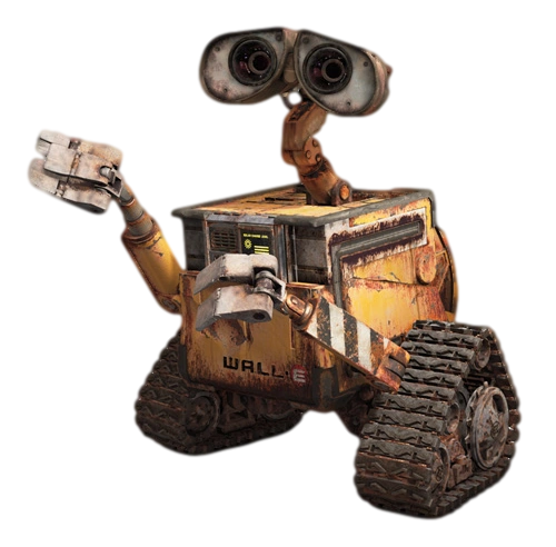
For my project, I’m working on a Human Following Robot – you know, something straight out of a sci-fi movie, and Wall-E definitely comes to mind. The whole idea is to create this robot buddy that can autonomously follow people around, kind of like a helpful sidekick. It hit me after watching Wall-E, and I thought, why not bring a touch of that magic into real life?
So, here’s the plan: I’ll be using sensors to catch someone’s presence and their moves. Think about it like a buddy who always walks by your side, adjusting its position as you go. No need for a remote or anything – it just picks up on your vibe and tags along. The key components here are these cool sensors – they’re like the robot’s eyes and ears, helping it figure out where you are and what you’re up to.
I was building the 3D printer for the lab and noticed how the extruder moves across the X and Y axes. There are two motors, each moving the extruder in one or the other axis. By working both motors together, the extruder can be moved to any X or Y position. This is where I got my final project idea from. I’m going to make a raised tray and fill it with sand, and place one metal ball bearing on the sand surface, like in this picture:
There’s going to be a magnet underneath the table, which attracts the ball, and by moving the magnet, I’ll be able to move the ball on the sand and draw patterns. The magnet is going to be moved across the X and Y axes using two motors, like in the 3D printer. There are a bunch of belts in the IM lab storage, just like the ones that are used in the 3D printer, and I’m hoping that I get to use those for my purposes. If not, I would probably have to order them myself.
This is where p5 comes in: the Arduino controls the motors, but the Arduino is controlled by user input from p5. Users can maybe use keyboard arrows to move a virtual ball on the canvas, and that motion will be replicated by the real ball. I haven’t really pinned down what the user interaction would look like: it could also be users painting with their finger on a touch screen, but the issue with that might be that users might just move their fingers faster than the motors are able to move the ball, so that wouldn’t work. One simple way to tackle this would be to just reduce the frame rate on p5, so that users can’t draw that fast, and the motors are able to keep up.
I would also want to program a “default” mode, so that when there’s no users, the ball draws nice, symmetric shapes on its own. That way, the project could be a nice, standalone art installation, but also interactive.
The writer of Design Meets Disability delves into using design to make the needs of disabled people more fashionable. However, they fail to take into account that not every disabled person wants to make their disability their entire personality. While some of the designs he showed were stunning, they may be too “out there” for someone who doesn’t want to make a big deal of their disability. I know a couple of disabled people who would actually be uncomfortable with the idea that their disability would be used as a fashion statement. That being said, there is nothing wrong with making it a fashion statement for those who willingly choose to do so. I would also like to point out that the writer made it seem that the “normal” products for disabled people were not good enough. In reality, most people can’t afford to get designer prosthetics or hearing aids. They should not be made to feel like they’re getting the short end of the stick.
I particularly liked how the writer mentioned how hearing aid companies are trying to make their products more invisible by making them smaller and hidden. On the other hand, eyeglass companies are trying to make their products more out there to show off as a fashion statement. I never noticed this contrast before but it was quite interesting to realize. I think that perhaps because glasses are more commonly worn than hearing aids that they’re more widely accepted and people are more comfortable with wearing them publicly instead of keeping them hidden like hearing aids. Furthermore, the writer also delves into modern technologies that value simplicity and accessibility. I found this to be very different compared to his original view where he wanted disability products to be less simple and more fashion-forward. As someone who is into fashion, I would want nothing more than to make a statement unless it comes in the way of my comfort and accessibility. While some of the designs he showed were gorgeous, some like the hand prosthetic looked less functional and more just a fashion statement.
To move the ellipse in the middle of the screen, I used the example from class with small changes. Here is the sketch:
The ellipse moving part:
let x = map(alpha, 0, 1023, 0, width);
  ellipse(x, height/2, 40, 40)
Exercise 2:
I wanted the brightness level of an LED to be matched with the falling of the ellipse on P5.js. The LED is the brightest when the ellipse is at the bottom of the canvas, thus making the LED brighter as the ellipse falls. Here is the sketch:
P5 code:
let y = 0;

function setup() {
  createCanvas(640, 240);
  textSize(18);
}

function draw() {

  background(0);

  // the other value controls the text's transparency value
  fill(255);
  ellipse(width/2, y, 40, 40);
  y+=1;

  if (y>height){
    y=0
  }

  if (!serialActive) {
    text("Press Space Bar to select Serial Port", 20, 30);
  } else {
    text("Connected", 20, 30);


    // Print the current values
    //text('rVal = ' + str(rVal), 20, 50);
    text('alpha = ' + str(alpha), 20, 70);

  }

  print(y)


}

function keyPressed() {
  if (key == " ") {
    // important to have in order to start the serial connection!!
    setUpSerial();
  }
}

// This function will be called by the web-serial library
// with each new *line* of data. The serial library reads
// the data until the newline and then gives it to us through
// this callback function
function readSerial(data) {
  ////////////////////////////////////
  //READ FROM ARDUINO HERE
  ////////////////////////////////////

  if (data != null) {
    // make sure there is actually a message
    // split the message
    let fromArduino = split(trim(data), ",");
    // if the right length, then proceed
    if (fromArduino.length == 2) {
      // only store values here
      // do everything with those values in the main draw loop

      // We take the string we get from Arduino and explicitly
      // convert it to a number by using int()
      // e.g. "103" becomes 103
      //rVal = int(fromArduino[0]);
      alpha = int(fromArduino[1]);
    }

    //////////////////////////////////
    //SEND TO ARDUINO HERE (handshake)
    //////////////////////////////////
    let sendToArduino = y + "\n";
    writeSerial(sendToArduino);
  }
}
Arduino code:
int ledPin = 11;  // LED connected to pin 11

void setup() {
  Serial.begin(9600);
  pinMode(ledPin, OUTPUT);

  // Blink the LED to indicate setup
  digitalWrite(ledPin, HIGH);
  delay(200);
  digitalWrite(ledPin, LOW);

  // Start the handshake
  while (!Serial.available()) {
    Serial.println("0");  // Send a starting message
    delay(300);
  }
}

void loop() {
  // Wait for data from p5.js before doing something
  while (Serial.available()) {
    int y = Serial.parseInt();
    if (Serial.read() == '\n') {
      // Map the y value to the LED brightness (0-255)
      int brightness = map(y, 0, 240, 0, 255);
      analogWrite(ledPin, brightness);

      // Print the received y value for debugging
      Serial.println(y);
    }
  }
}
Exercise 3:
I made the gravity weaker so that the LED blinking is more clearly visible.
P5 code:
let velocity;
let gravity;
let position;
let acceleration;
let wind;
let drag = 0.99;
let mass = 50;
let alpha = 0; // Initialize alpha

function setup() {
  createCanvas(640, 360);
  noFill();
  position = createVector(width / 2, 0);
  velocity = createVector(0, 0);
  acceleration = createVector(0, 0);
  gravity = createVector(0, 0.05 * mass);
  wind = createVector(0, 0);
}

function draw() {
  background(255);

  // Update wind based on alpha
  wind.x = alpha;

  applyForce(wind);
  applyForce(gravity);

  velocity.add(acceleration);
  velocity.mult(drag);
  position.add(velocity);
  acceleration.mult(0);

  ellipse(position.x, position.y, mass, mass);

  if (position.y > height - mass / 2) {
    velocity.y *= -0.9; // A little dampening when hitting the bottom
    position.y = height - mass / 2;
  }

  print(int(position.y), alpha);
}

function applyForce(force) {
  // Newton's 2nd law: F = M * A
  // or A = F / M
  let f = p5.Vector.div(force, mass);
  acceleration.add(f);
}

function readSerial(data) {
  if (data != null) {
    // make sure there is actually a message
    // split the message
    let fromArduino = split(trim(data), ",");
    // if the right length, then proceed
    if (fromArduino.length == 2) {
      // only store values here
      // do everything with those values in the main draw loop
      alpha = int(fromArduino[1]);
    }

    //////////////////////////////////
    // SEND TO ARDUINO HERE (handshake)
    //////////////////////////////////
    let sendToArduino = int(position.y) + "\n";
    writeSerial(sendToArduino);
  }
}

function keyPressed(){

  if (key == " ") {
    // important to have in order to start the serial connection!!
    setUpSerial();

}
}
Arduino code:
const int potPin = A0;
const int ledPin = 13;

int potValue;
int ballPosition;
bool isBouncing = false;

void setup() {
  pinMode(ledPin, OUTPUT);
  Serial.begin(9600);
}

void loop() {
  // Read the value from the potentiometer
  potValue = analogRead(potPin);

  // Map the potentiometer value to the range of wind force
  int mappedWind = map(potValue, 0, 1023, -1, 1);

  // Send the mapped wind force value to the computer through serial
  Serial.print("0,");
  Serial.println(mappedWind);

  // Read the ball's position from p5.js
  if (Serial.available() > 0) {
    ballPosition = Serial.parseInt();
  }

  // Check if the ball bounces
  if (ballBouncesCondition()) {
    if (!isBouncing) {
      // Turn on the LED when the ball starts bouncing
      digitalWrite(ledPin, HIGH);
      isBouncing = true;
    }
  } else {
    // Turn off the LED if the ball is not bouncing
    digitalWrite(ledPin, LOW);
    isBouncing = false;
  }


}

bool ballBouncesCondition() {
  return ballPosition >= 320;
}
Exercise 1: make something that uses only one sensor on Arduino and makes the ellipse in p5 move on the horizontal axis, in the middle of the screen, and nothing on arduino is controlled by p5
I used an Arduino potentiometer to change the horizontal position of the ellipse in the p5js sketch. The values read from the potentiometer are mapped to the x coordinates of the ellipse, moving it across the horizontal axis in the middle of the screen.
Video of implementation:
Code:
let left = 0;

function setup() {
  createCanvas(400, 400);
}

function draw() {
  background(220);
  fill("red");
  ellipse(left, 50, 50, 50);
}

function keyPressed() {
  if (key == " ") {
    // important to have in order to start the serial connection!!
    setUpSerial();
  }
}

function readSerial(data) {
  left = map(data, 0, 1023, 0, 400);
}

//// Arduino Code
/*

void setup() {
  // put your setup code here, to run once:
  Serial.begin(9600);

}

void loop() {
  // put your main code here, to run repeatedly:
  int sensor = analogRead(A0);
  delay(5);
  Serial.println(sensor);

}

*/
Exercise 2: make something that controls the LED brightness from p5
To control the led brightness through P5JS, I created a brightness slider similar to that in our smartphones. The value of the slider is sent to Arduino to be the value of the analog write of the led and change its brightness.
Video of implementation:
Code:
let brightnessSlider;
let brightnessValue = 0;

function setup() {
  createCanvas(400, 200);

  // Create a brightness slider
  brightnessSlider = createSlider(0, 255, 128);
  brightnessSlider.position(width/2-50, height/2);
  brightnessSlider.style('width', '100px');
}

function draw() {
  background(255);

  // Get the brightness value from the slider
  brightnessValue = brightnessSlider.value();
}

function keyPressed() {
  if (key == " ") {
    // important to have in order to start the serial connection!!
    setUpSerial();
  }
}

function readSerial(data) {
  console.log(data);
    let dataToSend = brightnessValue + ", \n";
    writeSerial(dataToSend);
}

///Arduino COde
/*

const int ledPin = 9;  // Digital output pin for the LED

void setup() {
  pinMode(ledPin, OUTPUT);

  // Start serial communication
  Serial.begin(9600);
}

void loop() {
  Serial.println("sensor");
  // Check if data is available from p5.js
  if (Serial.available() > 0) {
    // Read the brightness value from p5.js
    int brightness = Serial.parseInt();

    // Map the received value to the LED brightness range
    brightness = constrain(brightness, 0, 255);

    // Set the LED brightness
    analogWrite(ledPin, brightness);
  }
}

*/
Exercise 3: take the gravity wind example and make it so every time the ball bounces one led lights up and then turns off, and you can control the wind from one analog sensor
When the ball touches the ground, the value of the variable Led changes accordingly (either 0 or 1) and then sent to the Arduino to toggle the led at pin 9. For the wind effect, I used a potentiometer where its values are mapped to values between -2 and 2, making a smooth wind effect moving the ball horizontally.
Video of implementation:
Code:
let velocity;
let gravity;
let position;
let acceleration;
let wind;
let drag = 0.99;
let mass = 50;
let led = 0;

function setup() {
  createCanvas(640, 360);
  noFill();
  position = createVector(width/2, 0);
  velocity = createVector(0,0);
  acceleration = createVector(0,0);
  gravity = createVector(0, 0.5*mass);
  wind = createVector(0,0);
}

function draw() {
  background(255);
  applyForce(wind);
  applyForce(gravity);
  velocity.add(acceleration);
  velocity.mult(drag);
  position.add(velocity);
  acceleration.mult(0);
  ellipse(position.x,position.y,mass,mass);
  if (position.y > height-mass/2) {
      velocity.y *= -0.9;  // A little dampening when hitting the bottom
      position.y = height-mass/2;
  }
  if(position.y == height-mass/2 && (velocity.y > 0.5 || velocity.y < -0.5)){
    led = 1;
  }else{
    led = 0;
  }
}

function applyForce(force){
  // Newton's 2nd law: F = M * A
  // or A = F / M
  let f = p5.Vector.div(force, mass);
  acceleration.add(f);
}

function keyPressed(){
  if (key == "n") {
    // important to have in order to start the serial connection!!
    setUpSerial();
  }
  if (key==' '){
    mass=random(15, 80);
    position.y=-mass;
    velocity.mult(0);
  }
}

function readSerial(data) {

  if (data != null) {
    // make sure there is actually a message
    // split the message
    wind.x = data;

    //////////////////////////////////
    //SEND TO ARDUINO HERE (handshake)
    //////////////////////////////////
    let sendToArduino = led + "\n";
    writeSerial(sendToArduino);
  }
}

///Arduino COde
/*

int ledPin = 9;

void setup() {
  // Start serial communication so we can send data
  // over the USB connection to our p5js sketch
  Serial.begin(9600);
  pinMode(ledPin, OUTPUT);
}

void loop() {
  int sensor = analogRead(A0);
  int wind = map(sensor, 0, 1023, -2, 2);
  Serial.println(wind);
  delay(10);
  if (Serial.available() > 0) {
    // Read the brightness value from p5.js
    int touch = Serial.parseInt();
    // Set the LED brightness
    digitalWrite(ledPin, touch);
  }
}
*/
For this exercise, I just repurposed the code from class. I kept the Arduino IDE code the same. I used the alpha value (which was the reading from the photoresistor) and added these three lines of code to move the ellipse along the horizontal axis.
let x = map(alpha, 0, 1023, 0, width);
fill(0, 0, 0);
ellipse(x, height/2, 20, 20);
2:
For this, I modified the Arduino code slightly.
// Week 11.2 Example of bidirectional serial communication

// Inputs:
// - A0 - sensor connected as voltage divider (e.g. potentiometer or light sensor)
// - A1 - sensor connect
  pinMode(LED_BUILTIN, OUTPUT);

  // Outputs on these pins
  pinMode(leftLedPin, OUTPUT);
  pinMode(rightLedPin, OUTPUT);

  // Blink them so we can check the wiring
  digitalWrite(leftLedPin, HIGH);
  digitalWrite(rightLedPin, HIGH);
  delay(200);
  digitalWrite(leftLedPin, LOW);
  digitalWrite(rightLedPin, LOW);


  // start the handshake
  while (Serial.available() <= 0) {
    // digitalWrite(LED_BUILTIN, HIGH); // on/blink while waiting for serial data
    Serial.println("0,0"); // send a starting message
    delay(300);            // wait 1/3 second
    // digitalWrite(LED_BUILTIN, LOW);
    delay(50);
  }
}

void loop() {
  // wait for data from p5 before doing something
  while (Serial.available()) {
    digitalWrite(LED_BUILTIN, HIGH); // led on while receiving data

    int left = Serial.parseInt();
    int right = Serial.parseInt();
    if (Serial.read() == '\n') {
      brightness = map(left, 0, 1023, 255, 0);
      analogWrite(rightLedPin, brightness);
      int sensor = analogRead(A0);
      delay(5); // delay bc consecutive analog reads might make some noise
      int sensor2 = analogRead(A1);
      delay(5);
      Serial.print(sensor);
      Serial.print(',');
      Serial.println(sensor2);
    }
  }
  digitalWrite(LED_BUILTIN, LOW);
}
And here is the p5.js code:
let rVal = 0;
let alpha = 255;
let left = 0; // True (1) if mouse is being clicked on left side of screen
let right = 0; // True (1) if mouse is being clicked on right side of screen
let slider;

function setup() {
  createCanvas(640, 480);
  textSize(18);
  slider = createSlider(0, 255, 0);
}

function draw() {
  // one value from Arduino controls the background's red color
  background(map(rVal, 0, 1023, 0, 255), 255, 255);

  // the other value controls the text's transparency value
  fill(255, 0, 255, map(alpha, 0, 1023, 0, 255));

  if (!serialActive) {
    text("Press Space Bar to select Serial Port", 20, 30);
  } else {
    text("Connected", 20, 30);


    // Print the current values
    text('rVal = ' + str(rVal), 20, 50);
    text('alpha = ' + str(alpha), 20, 70);
    text('brightness = ' + str(slider.value()), 20, 90)


  }

}

function keyPressed() {
  if (key == " ") {
    // important to have in order to start the serial connection!!
    setUpSerial();
  }
}

// This function will be called by the web-serial library
// with each new *line* of data. The serial library reads
// the data until the newline and then gives it to us through
// this callback function
function readSerial(data) {
  ////////////////////////////////////
  //READ FROM ARDUINO HERE
  ////////////////////////////////////

  if (data != null) {
    // make sure there is actually a message
    // split the message
    let fromArduino = split(trim(data), ",");
    // if the right length, then proceed
    if (fromArduino.length == 2) {
      // only store values here
      // do everything with those values in the main draw loop

      // We take the string we get from Arduino and explicitly
      // convert it to a number by using int()
      // e.g. "103" becomes 103
      rVal = int(fromArduino[0]);
      alpha = int(fromArduino[1]);
    }

    //////////////////////////////////
    //SEND TO ARDUINO HERE (handshake)
    //////////////////////////////////
    left = slider.value();
    right = slider.value();
    let sendToArduino = left + "," + right + "\n";
    writeSerial(sendToArduino);
  }
}
I created a slide that when the user moves back and forth, they can adjust the brightness of the blue LED (I used the blue LED because I used the exact same schematic, and the blue LED was connected to the digital PWM).
3:
The Arduino code I used for the third exercise was also very similar to the initial one provided:
// Week 11.2 Example of bidirectional serial communication

// Inputs:
// - A0 - sensor connected as voltage divider (e.g. potentiometer or light sensor)
// - A1 - sensor connected as voltage divider
//
// Outputs:
// - 2 - LED
// - 5 - LED

int leftLedPin = 2;
int rightLedPin = 5;
int brightness = 0;
void setup() {
  // Start serial communication so we can send data
  // over the USB connection to our p5js sketch
  Serial.begin(9600);

  // We'll use the builtin LED as a status output.
  // We can't use the serial monitor since the serial connection is
  // used to communicate to p5js and only one application on the computer
  // can use a serial port at once.
  pinMode(LED_BUILTIN, OUTPUT);

  // Outputs on these pins
  pinMode(leftLedPin, OUTPUT);
  pinMode(rightLedPin, OUTPUT);

  // Blink them so we can check the wiring
  digitalWrite(leftLedPin, HIGH);
  digitalWrite(rightLedPin, HIGH);
  delay(200);
  digitalWrite(leftLedPin, LOW);
  digitalWrite(rightLedPin, LOW);


  // start the handshake
  while (Serial.available() <= 0) {
    // digitalWrite(LED_BUILTIN, HIGH); // on/blink while waiting for serial data
    Serial.println("0,0"); // send a starting message
    delay(300);            // wait 1/3 second
    // digitalWrite(LED_BUILTIN, LOW);
    delay(50);
  }
}

void loop() {
  // wait for data from p5 before doing something
  while (Serial.available()) {
    digitalWrite(LED_BUILTIN, HIGH); // led on while receiving data

    int left = Serial.parseInt();
    int right = Serial.parseInt();
    if (Serial.read() == '\n') {
      // brightness = map(left, 0, 1023, 255, 0);
      digitalWrite(leftLedPin, left);
      digitalWrite(rightLedPin, right);
      // if (right == )
      int sensor = analogRead(A0);
      delay(5); // delay bc consecutive analog reads might make some noise
      int sensor2 = analogRead(A1);
      delay(5);
      Serial.print(sensor);
      Serial.print(',');
      Serial.println(sensor2);
    }
  }
  digitalWrite(LED_BUILTIN, LOW);
}
and this is the p5.js code:
let velocity;
let gravity;
let position;
let acceleration;
let wind;
let drag = 0.99;
let mass = 50;
let ledVal = 0;

function setup() {
  createCanvas(640, 360);
  noFill();
  position = createVector(width / 2, 0);
  velocity = createVector(0, 0);
  acceleration = createVector(0, 0);
  gravity = createVector(0, 0.5 * mass);
  wind = createVector(0, 0);
}

function draw() {
  background(255);

  if (!serialActive) {
    print("click to select Serial Port");
    fill(0);
    text("click to select Serial Port", 20, 30);
  } else {
    applyForce(wind);
    applyForce(gravity);
    velocity.add(acceleration);
    velocity.mult(drag);
    position.add(velocity);
    acceleration.mult(0);
    ledVal = 0;
    ellipse(position.x, position.y, mass, mass);
    if (position.y > height - mass / 2) {
      velocity.y *= -0.9; // A little dampening when hitting the bottom
      position.y = height - mass / 2;
      ledVal = 1;
    }
  }
}

function applyForce(force) {
  // Newton's 2nd law: F = M * A
  // or A = F / M
  let f = p5.Vector.div(force, mass);
  acceleration.add(f);
}


function keyPressed() {
  if (key == " ") {
    mass = random(15, 80);
    position.y = -mass;
    velocity.mult(0);
  }
}


function mousePressed() {
  if (!serialActive) {
    // important to have in order to start the serial connection!!
    setUpSerial();
  }
}

function readSerial(data) {


  if (data != null) {
    let fromArduino = split(trim(data), ",");
    // if the right length, then proceed
    if (fromArduino.length == 2) {
      let val = int(fromArduino[1]);
      wind.x = map(val, 0, 1023, -1, 1);
      print("wind", wind.x);
    }

    //////////////////////////////////
    //SEND TO ARDUINO HERE (handshake)
    //////////////////////////////////
    // left = slider.value();
    // right = slider.value();
    // console.log(position.y);

    let sendToArduino = ledVal + "," + ledVal + "\n";
    writeSerial(sendToArduino);
  }
}
The modifications in the p5.js code make it so that the user clicks on the screen to set up the serial. Once the game is started, the reading from the potentiometer is used to adjust the wind, and everytime the ball hits the ground the LED lights up. One thing that I struggled with was how to stop the LED from being perpetually lit up while the ball was just on the ground.
Pullin’s “Design Meets Disability” represents a good cross-section between, disability, fashion and design. In my opinion, he presents a story that goes beyond basic usability to embrace the core ideas of inclusion and empowerment, particularly when viewed through the lens of inclusivity and disability. In his book Pullin deftly demonstrates how assistive technology—like glasses, hear wear, and prosthetic limbs (leg wear)—has transformed into fashion statements. It’s amazing to see how design innovation has transformed these items from basic needs to unique expressions of identity and personal style to the point where today, spectacles are a fashion statement, unlike when they were only meant for individuals with disabilities like bad eyesight. Pullin discusses the significance of designs being both functional and aesthetically pleasing. He demonstrates how important it is to make things both visually appealing and accessible to those with disabilities. It’s similar to saying, “Hey, these things can look great AND they can help you!” Pullin emphasizes how a combination of good design and utility may change public perceptions of disability aids, increasing their social acceptance and appreciation.
Pullin discusses how keeping functionality without sacrificing simplicity can benefit those with disabilities. He illustrates how many people, regardless of ability, can profit from this type of design. He provides illustrations of universally usable, basic designs that improve the quality of life for those with impairments. It also emphasizes how crucial it is to pay attention to individuals with disabilities when creating these designs, as frequently we assume we know what is best for them based on presumptions and the stigmas society has attached to them. Therefore, I believe it is crucial to draw attention to these minute details that, not only benefit us but also those who are the primary beneficiaries of these designs.
This reading challenged me to consider creating not just an “interactive” design, but a GOOD interactive design that can improve everyone’s quality of life, particularly for those who are disabled. It’s not only about making things function; it’s also about making them user-friendly, simple and fashionable. I learned that good design considers everyone’s needs and can change how we see and accept things like disability aids. It’s about making the world more inclusive and thoughtful for everyone.
For this assignment, I collaborated with Shahd. We based our project on the example codes and made changes as we see appropriate. Shahd did the second exercise and I did the first exercise. We worked together to complete the third exercise.
Video:
Exercise 1:
p5 sketch:
int leftLedPin = 7;
int rightLedPin = 4;


void setup() {
 // Start serial communication so we can send data
 // over the USB connection to our p5js sketch
 Serial.begin(9600);


 // We'll use the builtin LED as a status output.
 // We can't use the serial monitor since the serial connection is
 // used to communicate to p5js and only one application on the computer
 // can use a serial port at once.
 pinMode(LED_BUILTIN, OUTPUT);


 // Outputs on these pins
 pinMode(leftLedPin, OUTPUT);
 pinMode(rightLedPin, OUTPUT);


 // Blink them so we can check the wiring
 digitalWrite(leftLedPin, HIGH);
 digitalWrite(rightLedPin, HIGH);
 delay(200);
 digitalWrite(leftLedPin, LOW);
 digitalWrite(rightLedPin, LOW);


 // start the handshake
  while (Serial.available() <= 0) {
    digitalWrite(LED_BUILTIN, HIGH);  // on/blink while waiting for serial data
    Serial.println("0,0");            // send a starting message
    delay(300);                       // wait 1/3 second
    digitalWrite(LED_BUILTIN, LOW);
    delay(50);
  }
}


void loop() {
 // wait for data from p5 before doing something
 while (Serial.available()) {
   digitalWrite(LED_BUILTIN, HIGH);  // led on while receiving data


   if (Serial.read() == '\n') {


     int sensor = analogRead(A1);  //potentiometer
     Serial.println(sensor);
   }
 }
 digitalWrite(LED_BUILTIN, LOW);
}
Exercise 2:
int leftLedPin = 6;


void setup() {
 // Start serial communication so we can send data
 // over the USB connection to our p5js sketch
 Serial.begin(9600);


 // We'll use the builtin LED as a status output.
 // We can't use the serial monitor since the serial connection is
 // used to communicate to p5js and only one application on the computer
 // can use a serial port at once.
 pinMode(LED_BUILTIN, OUTPUT);


 // Outputs on these pins
 pinMode(leftLedPin, OUTPUT);


 // start the handshake
 while (Serial.available() <= 0) {
   digitalWrite(LED_BUILTIN, HIGH);  // on/blink while waiting for serial data
   Serial.println("0,0");            // send a starting message
   delay(200);                       // wait 1/3 second
   digitalWrite(LED_BUILTIN, LOW);
   delay(200);
 }
}


void loop() {
 // wait for data from p5 before doing something
 while (Serial.available()) {
   digitalWrite(LED_BUILTIN, HIGH);  // led on while receiving data


   int brightness = Serial.parseInt();
   analogWrite(leftLedPin, brightness);
   if (Serial.read() == '\n') {
     Serial.println("0,0");
   }
 }
 digitalWrite(LED_BUILTIN, LOW);
}
Exercise 3:
int leftLedPin = 7;
int rightLedPin = 4;


void setup() {
 // Start serial communication so we can send data
 // over the USB connection to our p5js sketch
 Serial.begin(9600);


 // We'll use the builtin LED as a status output.
 // We can't use the serial monitor since the serial connection is
 // used to communicate to p5js and only one application on the computer
 // can use a serial port at once.
 pinMode(LED_BUILTIN, OUTPUT);


 // Outputs on these pins
 pinMode(leftLedPin, OUTPUT);
 pinMode(rightLedPin, OUTPUT);


 // Blink them so we can check the wiring
 digitalWrite(leftLedPin, HIGH);
 digitalWrite(rightLedPin, HIGH);
 delay(200);
 digitalWrite(leftLedPin, LOW);
 digitalWrite(rightLedPin, LOW);


 // start the handshake
  while (Serial.available() <= 0) {
    digitalWrite(LED_BUILTIN, HIGH);  // on/blink while waiting for serial data
    Serial.println("0,0");            // send a starting message
    delay(300);                       // wait 1/3 second
    digitalWrite(LED_BUILTIN, LOW);
    delay(50);
  }
}


void loop() {
 // wait for data from p5 before doing something
 while (Serial.available()) {
   digitalWrite(LED_BUILTIN, HIGH);  // led on while receiving data


   int LED_STATE = Serial.parseInt();
   //int right = Serial.parseInt();
   if (Serial.read() == '\n') {
     digitalWrite(rightLedPin, LED_STATE);
     int sensor2 = analogRead(A1);
     delay(5);
     Serial.print(sensor2);
     Serial.print(',');
     Serial.println('Y');
   }
 }
 digitalWrite(LED_BUILTIN, LOW);
}