Concept:
For my final project, I pursued my initial idea and created a game that utilizes the ultrasonic sensor. The ultrasonic sensor will measure the distance from my hand and project that distance onto a ball’s horizontal position in p5. The ball can move left and right according to our hand movement. Multiple red rectangles are falling from above, and our job is to dodge them using our hands. There are also blue rectangles that spawn less frequently compared to the red ones. There is also a scoring system in which the score decreases by one after every frame, and hitting the red rectangles decreases the score by 2. Grabbing the blue rectangles that spawn less frequently is the only way to get a higher score. So the game becomes a fight against time and obstacles. As the score changes, the speaker that is connected to the breadboard also produces a different tone. Each score has its own unique tone produced by the speaker to make the game more engaging and fun. Therefore, this is a 2-way communication game, from p5 to Arduino and Arduino to p5.
Arduino:
Arduino will basically send the distance measured using the ultrasonic sensor to p5.Js. The Arduino side of the code will receive a score value from the p5. Arduino will input the echo pin(from ultrasonic sensor reading) and outputs both the trig pin(from ultrasonic) and speaker pin(value received from p5).
Here is my code for it so far:
const int trigPin = 11;
const int echoPin = 12;
const int speakerPin = 9;

void setup() {
  // Start serial communication so we can send data
  // over the USB connection to our p5js sketch
  Serial.begin(9600);
  pinMode(LED_BUILTIN, OUTPUT);

  // Outputs on these pins
  pinMode(trigPin, OUTPUT);
  pinMode(echoPin, INPUT);
  pinMode(speakerPin, OUTPUT);

  //start the handshake
  while (Serial.available() <= 0) {
    digitalWrite(LED_BUILTIN, HIGH); // on/blink while waiting for serial data
    Serial.println("0,0"); // send a starting message
    delay(300);            // wait 1/3 second
    digitalWrite(LED_BUILTIN, LOW);
    delay(50);
  }
}

void loop() {
  // sends a short pulse of ultrasonic sensor and waits a bit then receives it
  digitalWrite(trigPin, LOW);
  delayMicroseconds(2);
  digitalWrite(trigPin, HIGH);
  delayMicroseconds(10);
  digitalWrite(trigPin, LOW);

  // Time it takes for the pulse to travel back from the object long
  int duration = pulseIn(echoPin, HIGH);
  // Universal conversion of time into distance in cm
  int distance = duration * 0.034 / 2;

  //SENDS TO P5
  Serial.println(distance);
  delay(50);

  //GETS FROM P5
  int score = Serial.parseInt();
  // Map the score to a frequency for the speaker
  int frequency = map(score, 0, 100, 100, 4000);
  // Play the tone
  tone(speakerPin, frequency);
}
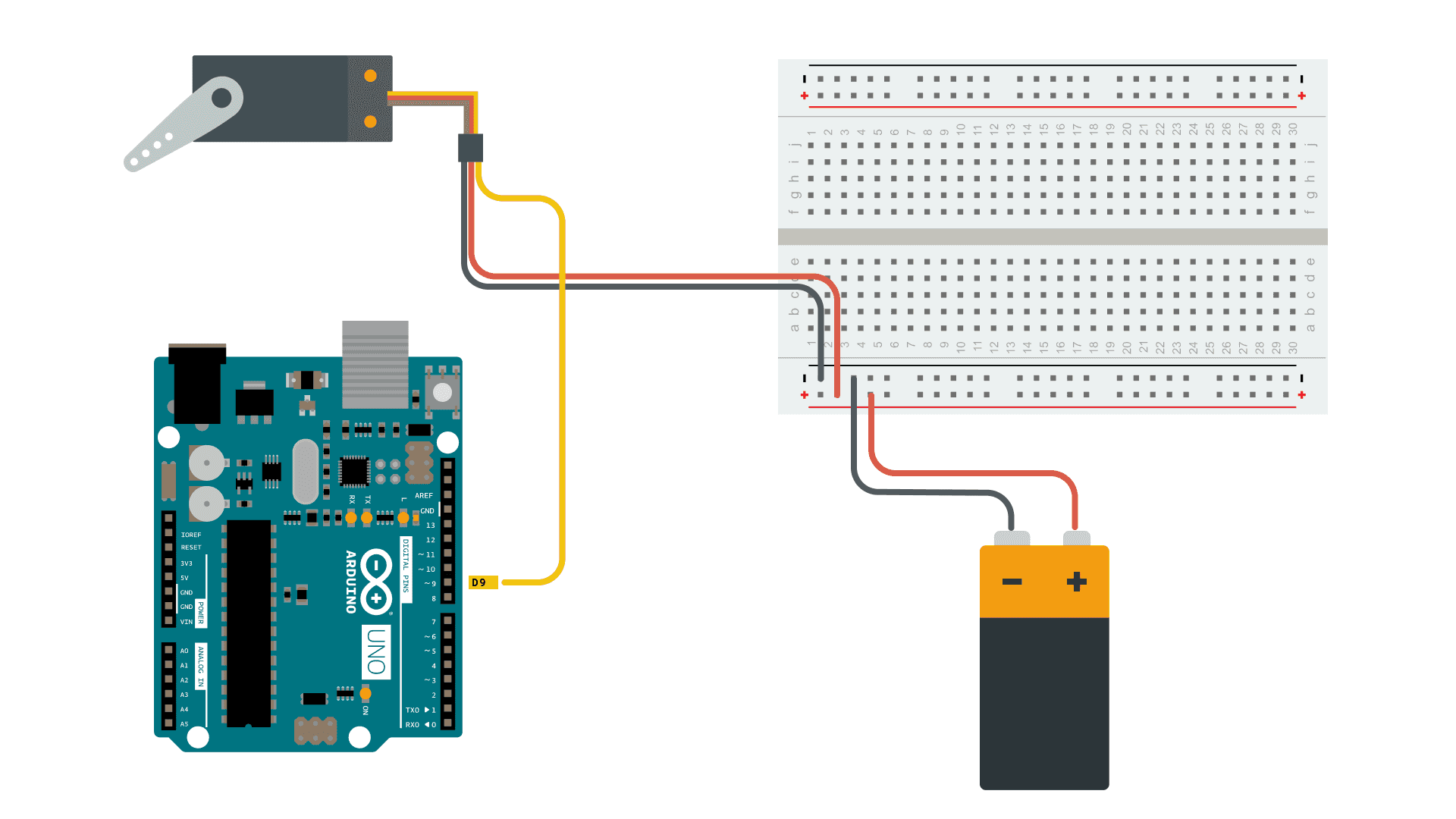
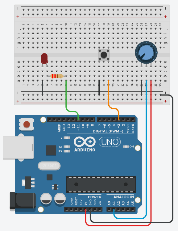
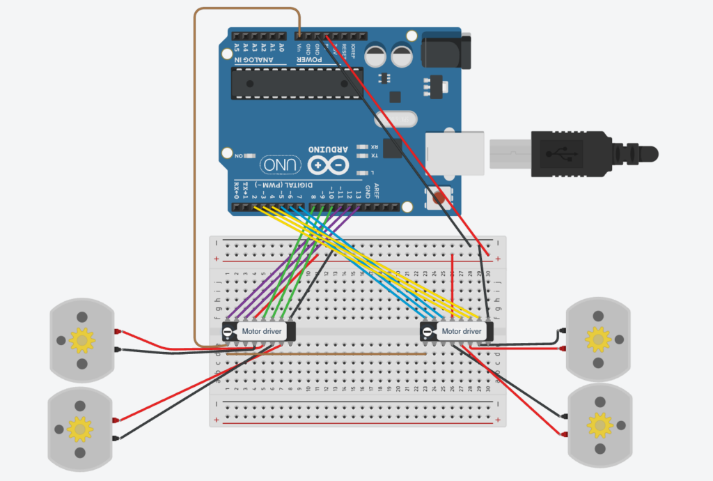
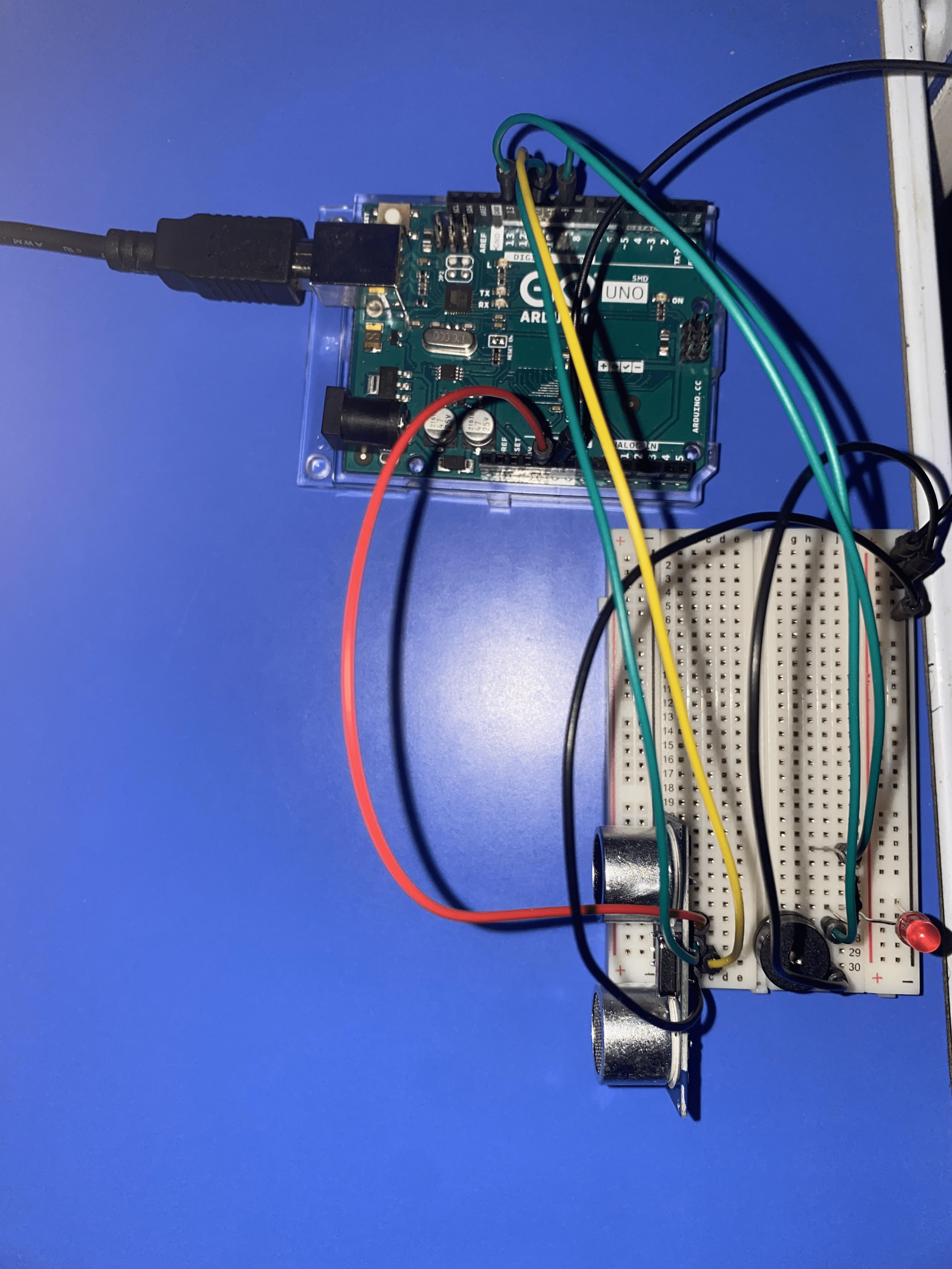
The Arduino board:

p5:
For the p5 side of the code, the p5 will receive the distance value measured from Arduino and map it onto the canvas. The p5 will also send a live score value to Arduino. There are multiple classes to my p5 code: ball class, Obstacle class, TimeRectangle class, a class for the port connection, and finally the main sketch.
This is my attached main sketch class:
//Initialize all variables
let knobValue = 0;
let targetKnobValue = 0;
let easing = 0.08; // Adjust this value for the desired level of smoothing
let score = 0;
let lastFrameCount;

//initialize the class objets
let obstacles = [];
let timeRectangles = [];
let ball;


function setup()
{
  createCanvas(400, 300);
  //call the ball object
  ball = new Ball(width / 2, height - 30, 20);
  //line of code to set lastframe to the new one
  lastFrameCount = frameCount;
}

function draw() {
  //set background
  background(220);

  //if function to connect port
  if (!serialActive)
  {
    fill(0);
    textSize(18);
    text("Press Space Bar to select Serial Port", 20, 30);
  }
  //else function if the port is connected
  else
  {
    // lerp function linear interpolates(smoothes the value we get from arduino using distance sensor)
    knobValue = lerp(knobValue, targetKnobValue, easing);
    //updates ball position according to distance sens
    ball.update(knobValue);

    // Draw ball
    ball.show();

    // Draw and move obstacles
    for (let i = obstacles.length - 1; i >= 0; i--) {
      obstacles[i].update();
      obstacles[i].show();

      // Remove obstacles that are off-screen
      if (obstacles[i].offscreen()) {
        obstacles.splice(i, 1);
      } else {
        // Check for collision with the ball
        if (obstacles[i].collision(ball)) {
          // Handle collision (e.g., decrease score)
          score= score-2;
          obstacles.splice(i, 1); // Remove the obstacle
        }
      }
    }

    // Draw and move timeRectangles(blue ones)
    for (let i = timeRectangles.length - 1; i >= 0; i--) {
      timeRectangles[i].update();
      timeRectangles[i].show();

      // Remove timeRectangles that are off-screen
      if (timeRectangles[i].offscreen()) {
        timeRectangles.splice(i, 1);
      } else {
        // Check for collision with the ball
        if (timeRectangles[i].collision(ball)) {
          // Handle collision (e.g., increase score)
          score += 5;
          timeRectangles.splice(i, 1); // Remove the timeRectangle
        }
      }
    }

    // Print the current knobValue
    fill(0);
    textSize(18);
    text('Knob Value: ' + str(knobValue), 20, 30);

    // Display score
    text("Score: " + score, 20, 60);

    // Spawn new obstacles and timeRectangles randomly
    if (random() < 0.01) {
      obstacles.push(new Obstacle());
    }
    if (random() < 0.005) {
      timeRectangles.push(new TimeRectangle());
    }

       // Update the score every second by subtracting current frame with last frame recorded in setup
    if (frameCount - lastFrameCount >= 60) {
      score = max(0, score - 1);
      lastFrameCount = frameCount;
    }

  }
}

function keyPressed() {
  if (key == " ") {
    // important to have in order to start the serial connection!!
    setUpSerial();
  }
}

function readSerial(data) {
  ////////////////////////////////////
  // READ FROM ARDUINO HERE
  ////////////////////////////////////

  if (data != null) {
    // Parse the data received from Arduino
    let fromArduino = split(trim(data), ",");
    targetKnobValue = int(fromArduino[0]);
    print(targetKnobValue);
  }

  //////////////////////////////////
  // SEND TO ARDUINO HERE
  //////////////////////////////////
  let sendToArduino= score + "\n";
   writeSerial(sendToArduino);
}
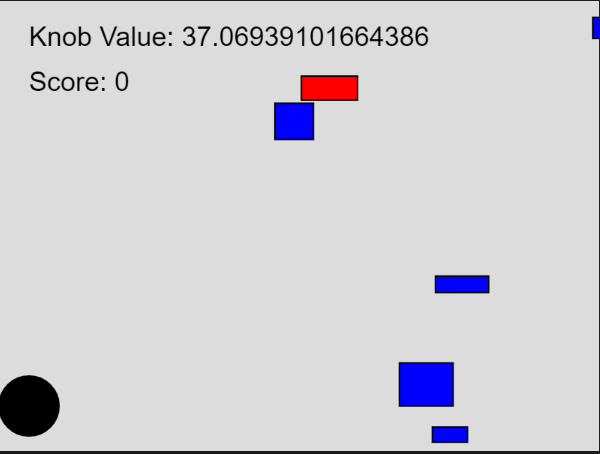
The P5 interface:

Future improvements:
As of now, I just put down the main codes and functions for both platforms. I will have to work more on the visuals, designs, and aethstics side as a whole of the p5 game.