Midterm Boat Afloat

Inspiration:

After our class discussion about breaking circuits with water, I stupidly thought I should make a boat just to see whether I could short circuit it. Unsurprisingly, I spent most of my time being worried about putting my boat in the water in the case that it would just sink and burn.

What: 

Simply, it is my attempt at create a remote controlled boat without the remote, but instead replaced by a joystick. It detects when the boat is too close to surrounding walls and stops the motor from moving. The joystick allows the boat to go backward, forward, left and right. If there is no interaction with the joystick, then the boat does not move.

Problems I Faced:

The first problem I had was trying to make the boat float. My original plan was to use half a styrofoam ball, which would hold the DC motors. However, the motor would easily touch water and when I tried it in a tub of water, the styrofoam ball would always tip over. To fix it, I decided to put that on top of a flat styrofoam surface, but it was very awkward and nothing fit well. 

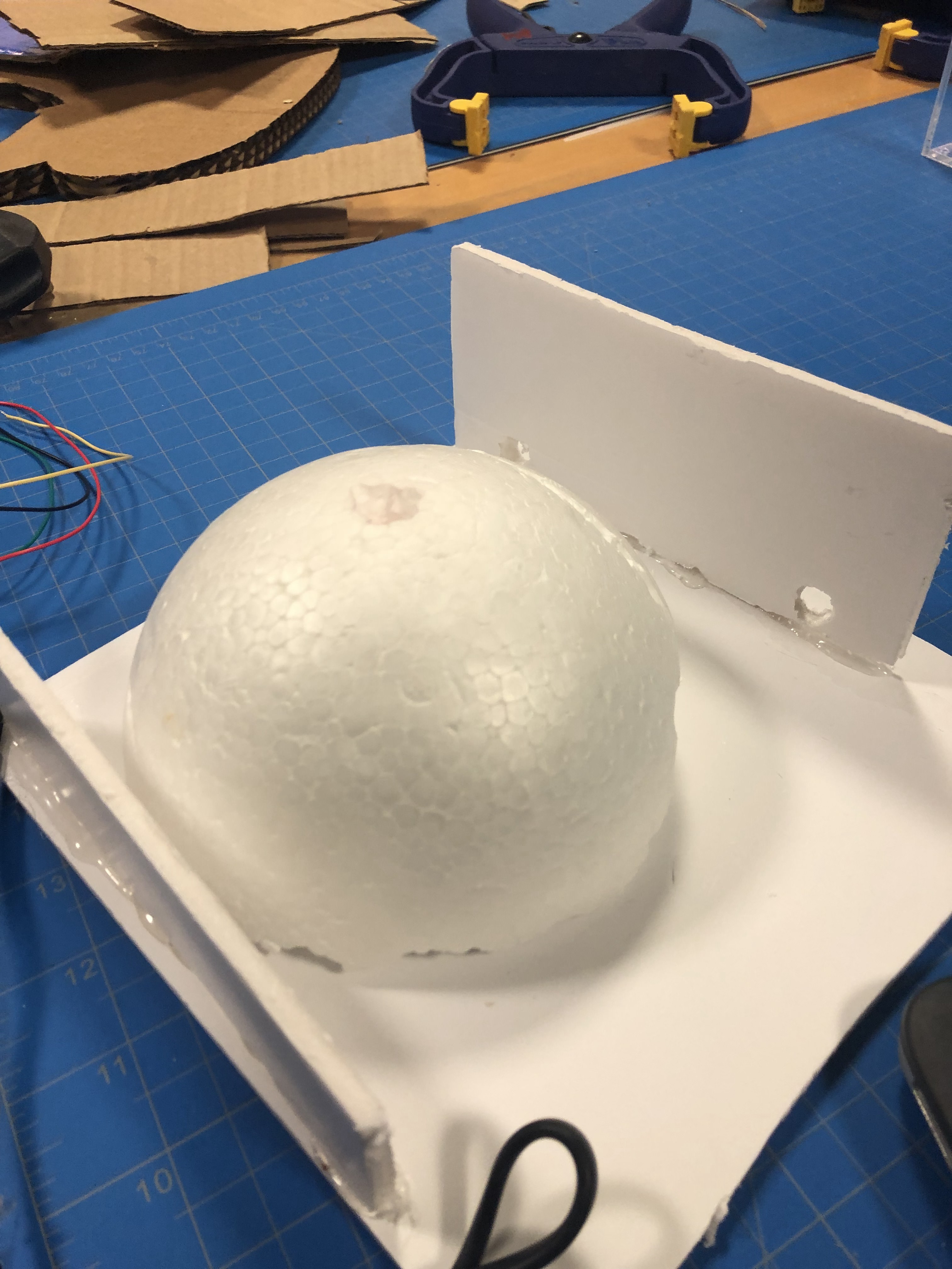
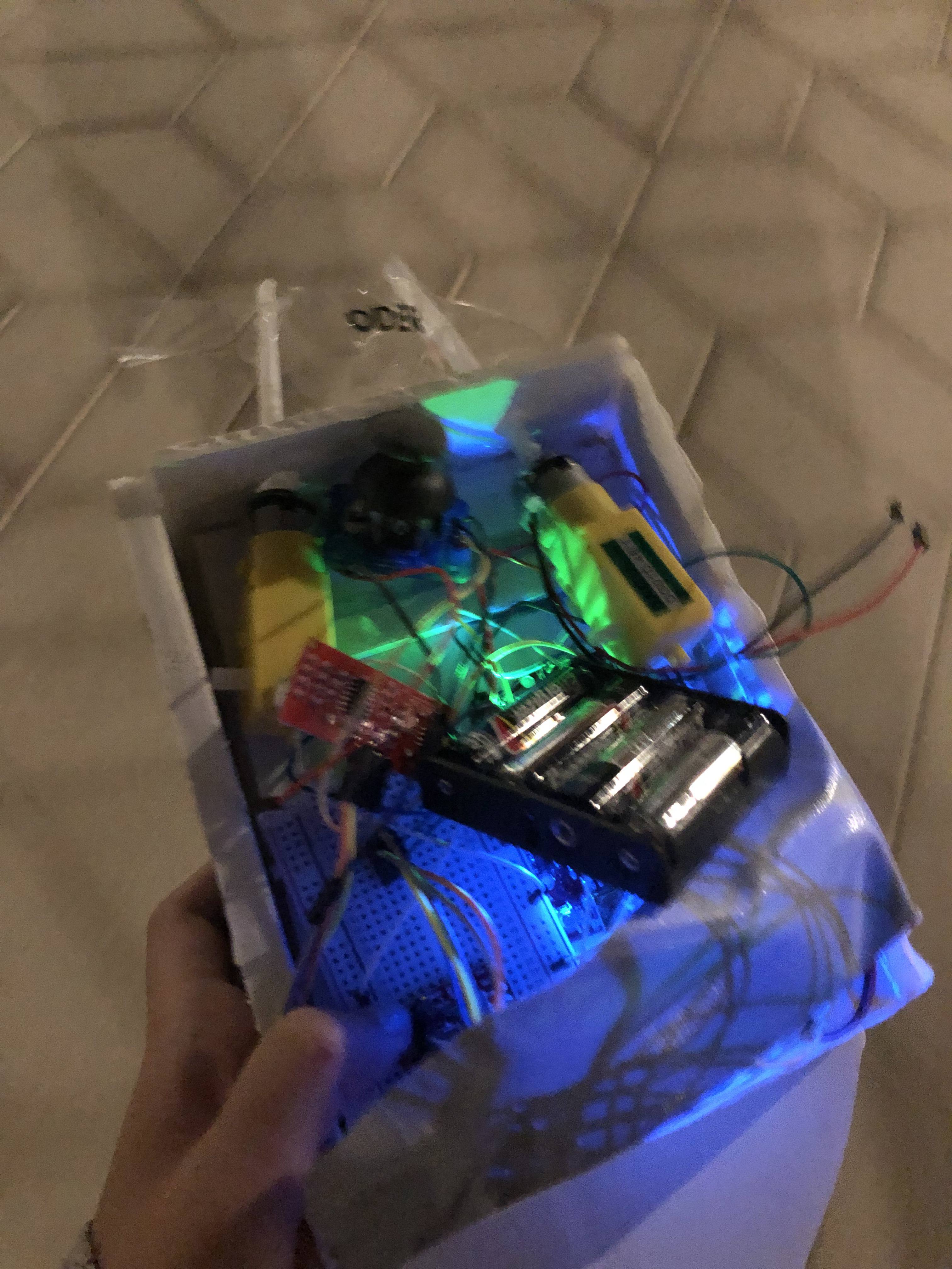
I finally decided to stack multiple foam planes on top of each other to give it enough height to stay away from the water and to carve out a tip in the front to make it resemble a boat. Although this was not the best solution, it still stopped water from touching any of the circuits. Water, however, still leaked through if it stays in water for too long. I ended up duct taping the bottom, but it was definitely just a temporary solution.

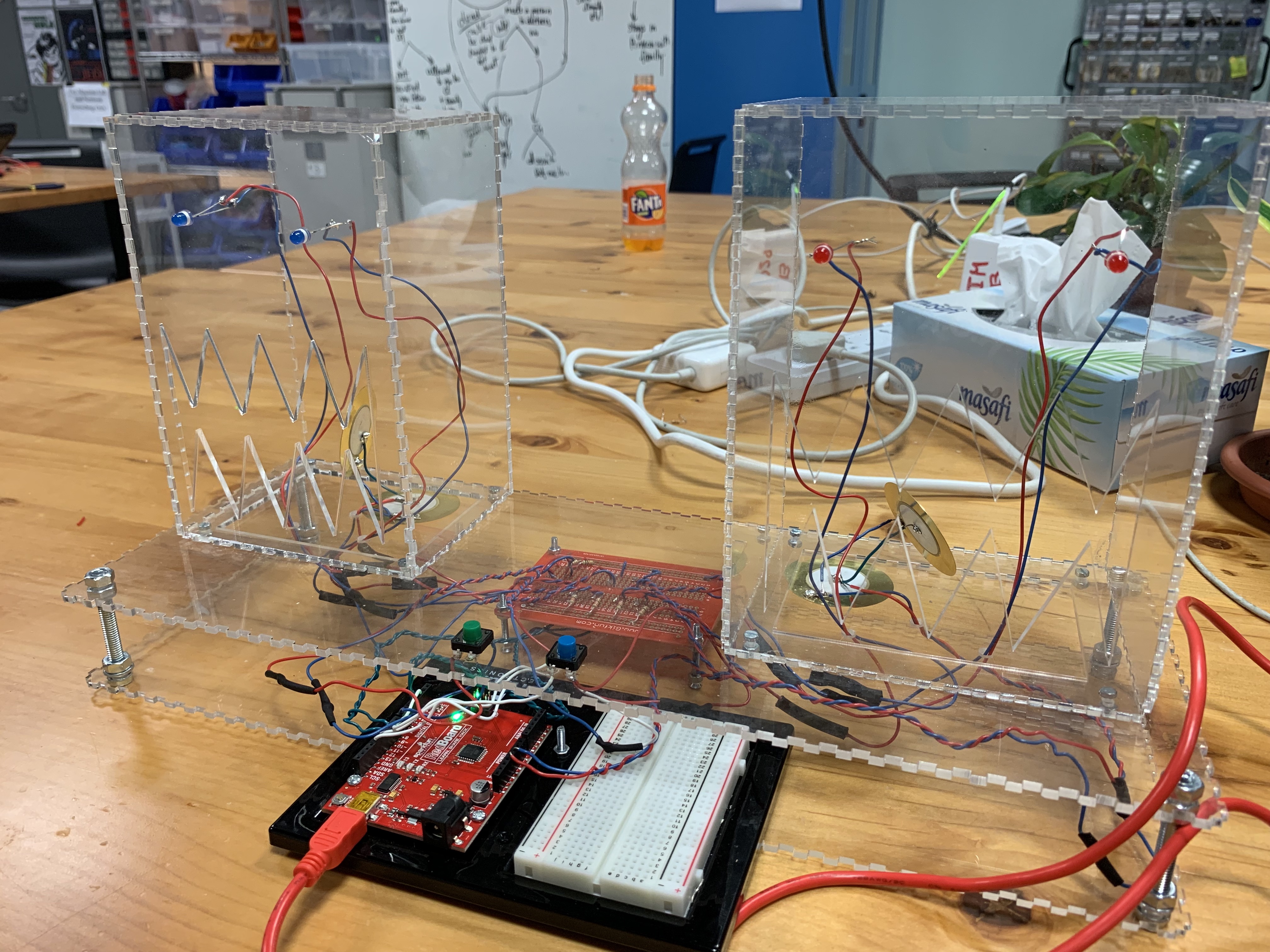
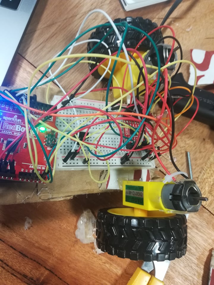
I also had trouble with figuring out how to use the motor driver especially in terms of how to hook it up to the breadboard and where the wires for the DC motors should go. I also had to learn about PWMs and how they work and how to make the DC motor turn left/right using digitalWrite(). It took a bit of time to configure everything correctly, but it worked in the end. Unfortunately, I still couldn’t figure out why the motor driver isn’t giving me the full 255 value for PWM. It did not give me the max speed I needed to turn the propeller under water.

If I had more time: 

The boat is, ascetically speaking, not a boat. It’s just styrofoam with a tip that makes it look like a boat. To improve on that, I would probably make the boat out of some lightweight wood that is curved correctly on the tip and sides so that it floats. There would be a hollow area for the breadboard and SparkFun circuit to sit on. It would also be covered in some way so that the water from the propeller would not accidentally carry water over the circuit.

For the joystick, I would detach it from the circuit and create a wireless board that has a joystick attached to it. By doing so, I would not have to follow the boat with the joystick and I wouldn’t have to worry about pulling out a wire by accident.

Additionally, if I have more Ultrasonic sensors, I would attach one on each side of the boat so it can detect all sides. In that way, I could either control the boat to stop completing if it’s close to anything or I could disable one of the directions to prevent the boat from hitting the side.

Last Thoughts:

I really enjoyed creating this project, although I spent a majority of the time figuring out the motor power, which led to a not-so-well designed boat. I enjoyed making the propellers and figuring out a way to extend the legs of the propeller so that it wouldn’t touch the water. It was also frustrating because I spent a long time trying to make a propeller out of a different material because I thought the plastic was too weak. However, it was because the motor wasn’t giving enough current to push the water.

const int leftMotor1 = 13, leftMotor2 = 12, PWMLeft = 11;
const int rightMotor1 = 8, rightMotor2 = 9, PWMRight = 10;

int trigPin = 2, echoPin = 3;

int x_direction, y_direction;
int X_PIN = A1, Y_PIN = A0;


int motorControl = 5;
int boatSpeed = 100;
int distanceInches = 0;

void setup() {
  pinMode(X_PIN, INPUT);
  pinMode(Y_PIN, INPUT);

  pinMode(leftMotor1, OUTPUT);
  pinMode(leftMotor2, OUTPUT);
  pinMode(PWMLeft, OUTPUT);

  pinMode(rightMotor1, OUTPUT);
  pinMode(rightMotor2, OUTPUT);
  pinMode(PWMRight, OUTPUT);

  pinMode(echoPin, INPUT);
  pinMode(trigPin, OUTPUT);

  pinMode(motorControl, OUTPUT);

  Serial.begin(9600);
}

void loop() {
  if (millis() % 100 == 0)
    distanceInches = getCurrentDistance();

  x_direction = analogRead(X_PIN);
  y_direction = analogRead(Y_PIN);

  int xSpeed = 0, ySpeed = 0;

  if (x_direction < 460) {
    xSpeed = map(x_direction, 0, 300, 255, 0);
  } else if (x_direction > 530) {
    xSpeed = map(x_direction, 530, 800, 0, 255);
  } else if (y_direction < 460) {
    ySpeed = map(y_direction, 0, 300, 255, 0);
  } else if (y_direction > 530) {
    ySpeed = map(y_direction, 530, 800, 0, 255);
  }

  Serial.print(distanceInches);
  Serial.print(" ");
  Serial.print(x_direction);
  Serial.print(" ");
  Serial.println(y_direction);

  if (distanceInches < 3) { //stop if too close to border
    analogWrite(PWMRight, 0);
    analogWrite(PWMLeft, 0);
  } else if (y_direction > 530) { //forward
    digitalWrite(leftMotor1, LOW);
    digitalWrite(leftMotor2, HIGH);
    digitalWrite(rightMotor1, LOW);
    digitalWrite(rightMotor2, HIGH);
    analogWrite(PWMRight, ySpeed);
    analogWrite(PWMLeft, ySpeed);
  } else if (y_direction < 460) {  //backward
    digitalWrite(leftMotor1, LOW);
    digitalWrite(leftMotor2, HIGH);
    digitalWrite(rightMotor1, HIGH);
    digitalWrite(rightMotor2, LOW);
    analogWrite(PWMRight, ySpeed);
    analogWrite(PWMLeft, ySpeed);
  } else if (x_direction < 460) {  //left
    digitalWrite(leftMotor1, LOW);
    digitalWrite(leftMotor2, HIGH);
    digitalWrite(rightMotor1, HIGH);
    digitalWrite(rightMotor2, LOW);
    analogWrite(PWMRight, 0);
    analogWrite(PWMLeft, xSpeed);
  } else if (x_direction > 530) {  //right
    digitalWrite(leftMotor1, HIGH);
    digitalWrite(leftMotor2, LOW);
    digitalWrite(rightMotor1, LOW);
    digitalWrite(rightMotor2, HIGH);
    analogWrite(PWMRight, xSpeed);
    analogWrite(PWMLeft, 0);
  }

}

float getCurrentDistance() {
  float dist;
  float echoT;

  digitalWrite(trigPin, LOW);
  delayMicroseconds(2);
  digitalWrite(trigPin, HIGH);
  delayMicroseconds(10);
  digitalWrite(trigPin, LOW);

  echoT = pulseIn(echoPin, HIGH);
  dist = echoT / 148.0;

  return dist;
}


Wheel of Paintings + an Interactive Story

My idea for my midterm changed a few times, beginning with a noise pollution detector, and then changing to a noise-canceling project to a wheel that spins depending on the pitch of the user’s voice. I just knew I wanted to do something with sounds. I wanted to discover more about sound sensors and how to link them to servos.

I couldn’t get a pitch reading using my RedBoard, so instead, I used a Teensy 3.2 board that can take in values and record the pitch and frequency of certain noises. It can also record a certain volume of sound. So I could set it to only read beyond a certain level of decibels and not below that.


For the wheel, I have 7 pieces of art, the cloud one being the most irrelevant one of the batch, and the rest are there to highlight women’s day this weekend. I also realized that the paintings have nothing to actually relate to the whole “using pitch to reveal things” concept so I decided to create a side three-part story inspired by “Goldilocks and the Three Bears”. The father, mother, and baby bear are bound to have different pitches because of very apparent reasons. The user has to use the pitch of their voice and adjust it to fit the set tone to make the servo turn to the specific bear horrified at some strange girl touching their food.


// Audio Tone Input
// Copyright 2013 Tony DiCola (tony@tonydicola.com)

// This code is part of the guide at http://learn.adafruit.com/fft-fun-with-fourier-transforms/

// Additions made by Aaron Sherwood 2019

#define ARM_MATH_CM4
#include <arm_math.h>


////////////////////////////////////////////////////////////////////////////////
// CONIFIGURATION
// These values can be changed to alter the behavior of the spectrum display.
////////////////////////////////////////////////////////////////////////////////
#include <Servo.h>  // add servo library
Servo myservo;  // create servo object to control a servo

int SAMPLE_RATE_HZ = 9000;             // Sample rate of the audio in hertz.
const int TONE_LOWS[] = {              // Lower bound (in hz) of each tone in the input sequence.
   200, 400, 600
};
const int TONE_HIGHS[] = {             // Upper bound (in hz) of each tone in the input sequence.
  200, 400, 600
};
int TONE_ERROR_MARGIN_HZ = 0;         // Allowed fudge factor above and below the bounds for each tone input.
int TONE_WINDOW_MS = 4000;             // Maximum amount of milliseconds allowed to enter the full sequence.

///////////
////////// SET THRSHOLED HERE DHABIA
float TONE_THRESHOLD_DB = 15.0;        // Threshold (in decibels) each tone must be above other frequencies to count.
///////////
///////////


const int FFT_SIZE = 256;              // Size of the FFT.  Realistically can only be at most 256
// without running out of memory for buffers and other state.
const int AUDIO_INPUT_PIN = 14;        // Input ADC pin for audio data.
const int ANALOG_READ_RESOLUTION = 10; // Bits of resolution for the ADC.
const int ANALOG_READ_AVERAGING = 16;  // Number of samples to average with each ADC reading.
const int POWER_LED_PIN = 13;          // Output pin for power LED (pin 13 to use Teensy 3.0's onboard LED).
// any other changes to the program.
const int MAX_CHARS = 65;              // Max size of the input command buffer


////////////////////////////////////////////////////////////////////////////////
// INTERNAL STATE
// These shouldn't be modified unless you know what you're doing.
////////////////////////////////////////////////////////////////////////////////

IntervalTimer samplingTimer;
float samples[FFT_SIZE * 2];
float magnitudes[FFT_SIZE];
int sampleCounter = 0;
char commandBuffer[MAX_CHARS];
int tonePosition = 0;
unsigned long toneStart = 0;


////////////////////////////////////////////////////////////////////////////////
// MAIN SKETCH FUNCTIONS
////////////////////////////////////////////////////////////////////////////////

void setup() {
  // Set up serial port.
  Serial.begin(38400);
  myservo.attach(3);  // attaches the servo on pin 9 to the servo object

  // Set up ADC and audio input.
  pinMode(AUDIO_INPUT_PIN, INPUT);
  analogReadResolution(ANALOG_READ_RESOLUTION);
  analogReadAveraging(ANALOG_READ_AVERAGING);

  // Turn on the power indicator LED.
  pinMode(POWER_LED_PIN, OUTPUT);

  // Clear the input command buffer
  memset(commandBuffer, 0, sizeof(commandBuffer));

  // Begin sampling audio
  samplingBegin();
}

void loop() {
  // Calculate FFT if a full sample is available.
  if (samplingIsDone()) {
    // Run FFT on sample data.
    arm_cfft_radix4_instance_f32 fft_inst;
    arm_cfft_radix4_init_f32(&fft_inst, FFT_SIZE, 0, 1);
    arm_cfft_radix4_f32(&fft_inst, samples);
    // Calculate magnitude of complex numbers output by the FFT.
    arm_cmplx_mag_f32(samples, magnitudes, FFT_SIZE);

    // Detect tone sequence.
    toneLoop();

    // Restart audio sampling.
    samplingBegin();
  }

  // Parse any pending commands.
  parserLoop();
}


////////////////////////////////////////////////////////////////////////////////
// UTILITY FUNCTIONS
////////////////////////////////////////////////////////////////////////////////

// Compute the average magnitude of a target frequency window vs. all other frequencies.
void windowMean(float* magnitudes, int lowBin, int highBin, float* windowMean, float* otherMean) {
  *windowMean = 0;
  *otherMean = 0;
  // Notice the first magnitude bin is skipped because it represents the
  // average power of the signal.
  for (int i = 1; i < FFT_SIZE / 2; ++i) {
    if (i >= lowBin && i <= highBin) {
      *windowMean += magnitudes[i];
    }
    else {
      *otherMean += magnitudes[i];
    }
  }
  *windowMean /= (highBin - lowBin) + 1;
  *otherMean /= (FFT_SIZE / 2 - (highBin - lowBin));
}

// Convert a frequency to the appropriate FFT bin it will fall within.
int frequencyToBin(float frequency) {
  float binFrequency = float(SAMPLE_RATE_HZ) / float(FFT_SIZE);
  return int(frequency / binFrequency);
}

// Convert intensity to decibels
float intensityDb(float intensity) {
  return 20.0 * log10(intensity);
}


////////////////////////////////////////////////////////////////////////////////
// SPECTRUM DISPLAY FUNCTIONS
///////////////////////////////////////////////////////////////////////////////

void toneLoop() {
  for (int i = 0; i < sizeof(TONE_LOWS)/sizeof(int); i++) {
    // Calculate the low and high frequency bins for the currently expected tone.
    int lowBin = frequencyToBin(TONE_LOWS[i]);
    int highBin = frequencyToBin(TONE_HIGHS[i]);
    // Get the average intensity of frequencies inside and outside the tone window.
    float window, other;
    windowMean(magnitudes, lowBin, highBin, &window, &other);
    window = intensityDb(window);
    other = intensityDb(other);
    // Check if tone intensity is above the threshold to detect a step in the sequence.
    if ((window - other) >= TONE_THRESHOLD_DB) {
      if (i == 0){
        Serial.println("low triggered");
        myservo.write(25);
        toneDetected();
      } else if (i == 1) {
        Serial.println("mid triggered");
        myservo.write(60);
        toneDetected();
      }
      else if (i == 2) {
        Serial.println("high triggered");
        myservo.write(110);

        toneDetected();
      }

    }
//    // Check if the entire sequence was passed through.
//    if (tonePosition >= sizeof(TONE_LOWS) / sizeof(int)) {
//      toneDetected();
//      tonePosition = 0;
//    }
  }
}

void toneDetected() {
  // Flash the LEDs four times.
  int pause = 150;
  for (int i = 0; i < 4; i++) {
    digitalWrite(POWER_LED_PIN, HIGH);
    delay(pause);
    digitalWrite(POWER_LED_PIN, LOW);
    delay(pause);
  }
}

////////////////////////////////////////////////////////////////////////////////
// SAMPLING FUNCTIONS
////////////////////////////////////////////////////////////////////////////////

void samplingCallback() {
  // Read from the ADC and store the sample data
  samples[sampleCounter] = (float32_t)analogRead(AUDIO_INPUT_PIN);
  // Complex FFT functions require a coefficient for the imaginary part of the input.
  // Since we only have real data, set this coefficient to zero.
  samples[sampleCounter + 1] = 0.0;
  // Update sample buffer position and stop after the buffer is filled
  sampleCounter += 2;
  if (sampleCounter >= FFT_SIZE * 2) {
    samplingTimer.end();
  }
}

void samplingBegin() {
  // Reset sample buffer position and start callback at necessary rate.
  sampleCounter = 0;
  samplingTimer.begin(samplingCallback, 1000000 / SAMPLE_RATE_HZ);
}

boolean samplingIsDone() {
  return sampleCounter >= FFT_SIZE * 2;
}


////////////////////////////////////////////////////////////////////////////////
// COMMAND PARSING FUNCTIONS
// These functions allow parsing simple commands input on the serial port.
// Commands allow reading and writing variables that control the device.
//
// All commands must end with a semicolon character.
//
// Example commands are:
// GET SAMPLE_RATE_HZ;
// - Get the sample rate of the device.
// SET SAMPLE_RATE_HZ 400;
// - Set the sample rate of the device to 400 hertz.
//
////////////////////////////////////////////////////////////////////////////////

void parserLoop() {
  // Process any incoming characters from the serial port
  while (Serial.available() > 0) {
    char c = Serial.read();
    // Add any characters that aren't the end of a command (semicolon) to the input buffer.
    if (c != ';') {
      c = toupper(c);
      strncat(commandBuffer, &c, 1);
    }
    else
    {
      // Parse the command because an end of command token was encountered.
      parseCommand(commandBuffer);
      // Clear the input buffer
      memset(commandBuffer, 0, sizeof(commandBuffer));
    }
  }
}

// Macro used in parseCommand function to simplify parsing get and set commands for a variable
#define GET_AND_SET(variableName) \
  else if (strcmp(command, "GET " #variableName) == 0) { \
    Serial.println(variableName); \
  } \
  else if (strstr(command, "SET " #variableName " ") != NULL) { \
    variableName = (typeof(variableName)) atof(command+(sizeof("SET " #variableName " ")-1)); \
  }

void parseCommand(char* command) {
  if (strcmp(command, "GET MAGNITUDES") == 0) {
    for (int i = 0; i < FFT_SIZE; ++i) {
      Serial.println(magnitudes[i]);
    }
  }
  else if (strcmp(command, "GET SAMPLES") == 0) {
    for (int i = 0; i < FFT_SIZE * 2; i += 2) {
      Serial.println(samples[i]);
    }
  }
  else if (strcmp(command, "GET FFT_SIZE") == 0) {
    Serial.println(FFT_SIZE);
  }
  GET_AND_SET(SAMPLE_RATE_HZ)
  GET_AND_SET(TONE_ERROR_MARGIN_HZ)
  GET_AND_SET(TONE_WINDOW_MS)
  GET_AND_SET(TONE_THRESHOLD_DB)
}


Midterm: Sunflower

My inspiration for this project was a painting by my favorite artist Van Gogh  (the Sunflowers) and I also wanted to create something that I would want to keep in my personal space. Therefore, my midterm project was a mimic of a ‘sunflower’ – a flower that would follow the direction of light.

I initially also wanted to make a flower that would open and close (as recommended by Aaron but despite trying to different methods – I felt as if I would be limited by time if I continued. So instead, I created my final one using two photoresistors and a servo.

For my code, since I used only one pin for both my photoresistors, the code was not too complicated. I used the sensor value (servoValue) to produce the values for which the servo should turn (servoTurn) and initially let this begin at a 90 degree angle. I also added a delay at the end so that allows the servo to reach the position indicated before the sensor senses anymore changes.

#include <Servo.h>

int sensorPin = A0;
int servoPin  = 9;

int sensorValue = 0;
int servoTurn = 90;
int tolerance = 20;

Servo myservo;

void setup() {
  Serial.begin(9600);
  pinMode(sensorPin, INPUT);
  myservo.attach(servoPin);
  myservo.write(servoTurn);
  // sets the degrees to which the servo is to be positioned
}

void loop() {

  sensorValue = analogRead(sensorPin);
  Serial.println(sensorValue);
  // print the sensor values
  
  if (sensorValue < (340-tolerance) )
    // perform the first check if the value read from before is less than the difference between 340
  {
    if (servoTurn < 180) servoTurn++; 
    // ++ increments x by one and returns the old value of x
    // perform a further check that the servo is not > 180 
  }
  
  if (sensorValue > (340+tolerance) )
    // value read by the sensor is compared with the sum of 340 + tolerance
  {
    if (servoTurn > 0) servoTurn--;
   // check that the angle the servo is located is not less than 0
  }


  myservo.write(servoTurn); 

  delay(50);
  // allows the servo to reach the position indicated before sensor sensing changes
}


Other sources/help/inspiration:

  • https://www.instructables.com/id/Light-Controlled-Servo/
  • https://www.instructables.com/id/Ever-Blooming-Mechanical-Tulip/
  • https://www.instructables.com/id/Create-an-Arduino-Controlled-Light-Following-Flowe/

Midterm Project – RED MONSTER and the BLUE MONSTER

My main interest for this project was the transferring the feedback of one medium to another medium, especially dealing with pattern of sound created using the piezo disc. And, for the midterm project, I have created two monsters: the RED and the BLUE indicated by the color of their eyes, where the blue monster follows the pattern played by the red monster. On the interface, there are two buttons: the green and the blue. When the green button is pressed, the red monster’s LED lights up, the buzzer inside it activates. The duration of the rest period in between the press and the duration of the buzzer activated will be saved, and when the blue button is pressed, the blue monster will follow the pattern that the red monster has played in a continuous loop.

For the structure of the data for this project, I have used the STL library which encompasses vector. Since, an array has to be predetermined with its size, I could not implement the array as my duration container when the length of the pattern is indeterminable. Whereas, using a vector, I can just push_back the new duration at the end – which served as a perfect container for this project.

Initially, I had multiple issue with the difference in the speed of the patter played for either monsters. At first, the saved duration values of the Red Monster were incrementing too fast, which I fixed using the modulus of it by 2500 to slow down the increments. Then, when the Blue Monster was playing the saved pattern, the intended speed of the pattern and the actual speed was different. So, I had to include careful selection of delay values to match them.

An interesting note about the project was that the enclosure was done with a transparent acrylic with the base being open on the sides. According to Critical Interface Toolbox by Joana Moll and Andrea Noni, one of the highlights of the definition of interface was “Users are entitled to know what the interface hides. Access to knowledge is a fundamental right“. Plus, after reading through different examples of the enclosure boxes, I was intrigued by the design of open-sides boxes, especially the “Moshi Moshi” created by Aaron. Therefore, I came to a conclusion to make the container of the project transparent for the audience to see what is happening underneath the system.

[Quick Play-through of the Project]

[Source Code for the Project]

#include <ArduinoSTL.h>

// ===== Declaring Variable Pin ===== //
const int triggerPin = 2;
const int buttonPin = 7;

const int buzzerOnePin = 12;
const int buzzerTwoPin = 13;

const int ledPinOne = 3;
const int ledPinTwo = 4;

const int ledPinThree = 10;
const int ledPinFour = 11;

// ===== Declaring Initial State ===== //
int prevPadState = 0;
int currentPadState = 0;

int currentTriggerState;
int prevTriggerState;

int savedRestDuration = 0;
int savedPlayedDuration = 0;

// Time Duration to slow down the accumulation of saved duration for the later loop
long timeDuration = 0;

// Conditions to check which loop to proceed:
// 1. TRUE :: BLUE MONSTER playing the saved duration of the vector
// 2. FALSE :: RED MONSTER playing and recording the pattern played into the vector
bool playLoopState = false;

unsigned long prevTime = 0;
unsigned long currentTime = 0;

// Interval Index is set as 1 so that when the trigger button is pressed,
// the savedNotes vector is played in the beginning disregarding the first rest period.
int intervalIndex = 1;

int resetIndex = 0;

// The container vector of durations for rest and playing of the note;
// ============================
// The even number index - REST;
// The odd number index - PLAY;
// ============================

std::vector<int> savedNotes;
 
void setup() {
  //Serial Port begin
  Serial.begin (9600);

  // RED MONSTER Buzzer
  pinMode(buzzerOnePin, OUTPUT);

  // BLUE MONSTER Buzzer
  pinMode(buzzerTwoPin, OUTPUT);

  // button - RED MONSTER
  // trigger - triggers the BLUE MONSTER to mimic the pattern of the RED MONSTER
  pinMode(buttonPin, INPUT);
  pinMode(triggerPin, INPUT);

  // RED MONSTER LEDs
  pinMode(ledPinOne, OUTPUT);
  pinMode(ledPinTwo, OUTPUT);

  // BLUE MONSTER LEDs
  pinMode(ledPinThree, OUTPUT);
  pinMode(ledPinFour, OUTPUT);
}
 
void loop() {

  currentTriggerState = digitalRead(triggerPin);
  currentPadState = digitalRead(buttonPin);
  
// ========================================================= //

  if (!playLoopState) {  
    if ((timeDuration%2500) == 0) {
      if (currentPadState == 1 && prevPadState == 1) {
        /*
         *  Button is being pressed = the buzzer is playing
         */
        Serial.print("Keep Playing!: ");
        tone(buzzerOnePin, 100);
        savedPlayedDuration++;
        Serial.println(savedPlayedDuration);
      }
  
      if (currentPadState == 0 && prevPadState == 0) {
        /*
         *  Button is not being pressed = the buzzer is resting
         */
        Serial.print("Keep Resting!: ");
        noTone(buzzerOnePin);
        savedRestDuration++;
        Serial.println(savedRestDuration);
      }
  
      if (currentPadState == 1 && prevPadState == 0) {
        /*
         *  The first loop when the button is pressed. This means that prior to the button press,
         *  the buzzer was resting. So I saved the accumulated duration of rest at this point.
         */
        tone(buzzerOnePin, 100);
        prevPadState = currentPadState; 

        // Start of playing duration;
        savedPlayedDuration++;

        digitalWrite(ledPinOne, HIGH);
        digitalWrite(ledPinTwo, HIGH);

        Serial.print("SAVED REST NOTE :");
        Serial.println(savedRestDuration);

        // Push the rest duration into the vector & reset the duration;
        savedNotes.push_back(savedRestDuration);
        savedRestDuration = 0;
        
      } else if (currentPadState == 0 && prevPadState == 1) {
         /*
         *  The first loop when the button is released. This means that prior to the button press,
         *  the buzzer was playing. So I saved the accumulated duration of playing at this point.
         */
        noTone(buzzerOnePin);
        prevPadState = currentPadState;

        // Start of rest duration;
        savedRestDuration++;

        digitalWrite(ledPinOne, LOW);
        digitalWrite(ledPinTwo, LOW);

        Serial.print("SAVED PLAY NOTE :");
        Serial.println(savedPlayedDuration);

        // Push the played duration into the vector & reset the duration;
        savedNotes.push_back(savedPlayedDuration);
        savedPlayedDuration = 0;
      }
    }
    
// ========================================================= //

  } else { 
    if (intervalIndex < savedNotes.size()) {
    /* ==========================================================
     * When the blue-button is pressed, the loop iterates through
     * the savedNotes vector from the designated interval index 
     * to the size of the vector.
     * ========================================================== */ 
      Serial.println(savedNotes[intervalIndex]);
      
      if ((currentTime) - (prevTime) <= savedNotes[intervalIndex]) {
        if ((intervalIndex % 2) == 0) {
          /* =========================================================
           * When the index of the vector saveNotes is an EVEN number,
           * the value of the vector at that index is the duration of
           * how long the "rest" period was. The loop is repeated until
           * currentTime - prevTime is equal to or larger than the
           * duration value of the saved rest.
           * ========================================================= */ 
          Serial.println("REST");
          noTone(buzzerTwoPin);
          digitalWrite(ledPinThree, LOW);
          digitalWrite(ledPinFour, LOW);
          delay(125);
        } else if ((intervalIndex % 2) == 1) {
          /* ========================================================
           * When the index of the vector saveNotes is an ODD number,
           * the value of the vector at that index is the duration of
           * how long the "played" period was. The loop is repeated 
           * until currentTime - prevTime is equal to or larger than 
           * the duration value of the saved rest.
           * ======================================================== */ 
          Serial.println("PLAYED");
          tone(buzzerTwoPin, 500);
          digitalWrite(ledPinThree, HIGH);
          digitalWrite(ledPinFour, HIGH);
          delay(125);
        }
      } else {
        /* ==========================================================
           * When the saved duration of the note/rest is done playing,
           * it will move on to the next index of the vector while
           * resetting the time.
           * ======================================================== */ 
        Serial.print("Next Index: ");
        Serial.println(intervalIndex);
        prevTime = currentTime;
        intervalIndex++;
      }
      
    } else {
       /* =========================================================
       * All the played/saved notes were iterated, repeating the
       * loop to play from the beginning of the vector
       * ========================================================= */ 
      Serial.println("Loop Finished & REPEAT");
      intervalIndex = 0;
      currentTime = 0;
      prevTime = 0;
    }
    
    currentTime++;
  }

  if (currentTriggerState == HIGH && prevTriggerState == LOW) {
    /* ================================
     * For the reset index:
     * 1. When the reset button is pressed for the first time, the index is    0 - signnaling the start the pattern loop for BLUE MONSTER
     * 2. When the reset button is pressed for the second time, the index is 1 - signaling the reset of the patter loop and go back to recording with the RED MONSTER
     * ================================*/
    if((resetIndex % 2) == 1) {
      Serial.println("CLEAR");
      
      // The vector is reset to be ready for next set of inputs from the RED MONSTER
      savedNotes.clear();
      intervalIndex = 1;

      savedRestDuration = 0;
      savedPlayedDuration = 0;

      noTone(buzzerTwoPin);
      noTone(buzzerTwoPin);

      digitalWrite(ledPinOne, LOW);
      digitalWrite(ledPinTwo, LOW);
      digitalWrite(ledPinThree, LOW);
      digitalWrite(ledPinFour, LOW);
    } 
    playLoopState = !playLoopState;
    resetIndex++;
    prevTriggerState = currentTriggerState;
  } else {
    prevTriggerState = currentTriggerState;
  }

  timeDuration++;
}


Midterm project. Maxim Blinov

Good day everyone!

So my project went as planned, except for some small changes. It is a tilt maze which actually work pretty well! Less detail, here is the video:

Here is my code which operates 2 servos and 2 pressure sensors.

#include <Servo.h>
 
Servo myServo;
Servo myServo1;


void setup() {
  myServo.attach(9);
  Serial.begin(9600);
  myServo1.attach(10);
  
}

void loop() {

  int pressure1 = analogRead(A0);
  int pressure2 = analogRead(A3);
  Serial.print(pressure1);
  Serial.print(" ");
  Serial.println(pressure2);
  int angle1 = map(pressure1, 0,970,90,30);
  int angle2 = map(pressure2, 0,970,110,30);
  myServo.write(angle1);
  myServo1.write(angle2);

}


Midterm: Light-Loving/Light-Fearing Vehicle

My initial plan for my midterm project was to produce a vehicle that would behave differently depending on how far it was from an object that is in its way. However, Aaron gave me a brilliant idea, which was to have a look at Braitenberg Vehicles, vehicles that would behave differently depending on its distance from light. This solved one of the biggest problems with my initial idea, because the Braitenberg vehicle would allow for greater interaction with users, allowing people to use flashlights on their phone  to navigate the vehicle.

My initial prototype was made of cardboard, however, this was structurally very weak and the right wheel would constantly fall off after prolonged movement. The vehicle was also lopsided, with the front being much lower to the ground than the back of the vehicle. This was not aesthetically pleasing and it resulted in some performance issues.

So I instead decided to use wood for the vehicle, which provides a more solid foundation, and solved the issue of the tilted vehicle. For the program itself, I ran an analogRead on the photoresistors positioned at the front of the vehicle, which would determine the speed of the wheels when exposed to varying light levels. This was effective at first, and my vehicle ran smoothly, however, for some reason, one photoresistor was getting much higher read values than the other. Despite trying to debug this and rewire the circuit, I decided to somewhat hardcode the machine. This actually turned out to be more effective, allowing the vehicle to be more attracted to light when the light in the environment was higher. I am sure that my code could have been more efficient.

Here is a video of the vehicle running in a dark room:

I also created a light-fearing version of the vehicle by changing the code by flipping the values for the wheel movement speeds. The vehicle does not work as well as the light-loving version, especially in environments that are moderately lit.

Here is the code for the light-loving version of the vehicle

const int pwma = 11 ; 
const int in_1 = 13 ;
const int in_2 = 12 ;
//first wheel ^
const int pwmb = 10 ; 
const int in_3= 8 ;
const int in_4 = 9 ;
//first wheel ^

const int photo1 = A4;
const int photo2 = A5;

int direct = 0;
int direct2 = 0;
void setup() {
  // put your setup code here, to run once:
   pinMode(pwma,OUTPUT) ; //we have to set PWM pin as output
   pinMode(pwmb,OUTPUT) ; //we have to set PWM pin as output
   pinMode(in_1,OUTPUT) ; //Logic pins are also set as output
   pinMode(in_2,OUTPUT) ;
   pinMode(in_3,OUTPUT) ; //Logic pins are also set as output
   pinMode(in_4,OUTPUT) ;
   Serial.begin(9600);
}

void loop() {
  // put your main code here, to run repeatedly:
   direct = random(0, 1);
   direct2 = (direct + 1) % 2;
   int photoOneValue = map(analogRead(A4), 0, 1023, 0, 255);
   int photoTwoValue = map(analogRead(A5), 0, 1023, 0, 255);
   if (photoTwoValue > 105) {
     digitalWrite(in_1, direct2) ;
     digitalWrite(in_2, direct) ;
     digitalWrite(in_3, direct2) ;
     digitalWrite(in_4, direct) ;
     analogWrite(pwma, 70);
     analogWrite(pwmb, 250);
     Serial.println("1");
} // speed in opposite direction to light
   //previous value was 85 ^

   else if (photoOneValue > 160) {
     digitalWrite(in_1, direct2) ;
     digitalWrite(in_2, direct) ;
     digitalWrite(in_3, direct2) ;
     digitalWrite(in_4, direct) ;
     analogWrite(pwma, 250);
     analogWrite(pwmb, 70);
     Serial.println("2");
   } 
   //previous value was 160 ^
   else if (photoTwoValue < 20 && photoOneValue < 80) {
     digitalWrite(in_1, direct2) ;
     digitalWrite(in_2, direct) ;
     digitalWrite(in_3, direct2) ;
     digitalWrite(in_4, direct) ;
     analogWrite(pwma, 110);
     analogWrite(pwmb, 110);
     Serial.println("3");
//constant slow speed when room is dim
 }
  else if (photoTwoValue > 20 && photoOneValue > 80 && photoOneValue < 160 && photoTwoValue < 105) {
     digitalWrite(in_1, direct2) ;
     digitalWrite(in_2, direct) ;
     digitalWrite(in_3, direct2) ;
     digitalWrite(in_4, direct) ;
     analogWrite(pwma, photoOneValue + 20);
     analogWrite(pwmb, photoTwoValue + 60);
     Serial.println("4");
//environment not dim, but light not sensitive enough to activate the two if statements on top, allows vehicle to move faster towards light/
  }
}

And below is the code for the “light-fearing” version of the vehicle:

const int pwma = 11 ; 
const int in_1 = 13 ;
const int in_2 = 12 ;

const int pwmb = 10 ; 
const int in_3= 8 ;
const int in_4 = 9 ;

const int photo1 = A4;
const int photo2 = A5;

int direct = 0;
int direct2 = 0;
void setup() {
  // put your setup code here, to run once:
   pinMode(pwma,OUTPUT) ; //we have to set PWM pin as output
   pinMode(pwmb,OUTPUT) ; //we have to set PWM pin as output

   pinMode(in_1,OUTPUT) ; //Logic pins are also set as output
   pinMode(in_2,OUTPUT) ;
   pinMode(in_3,OUTPUT) ; //Logic pins are also set as output
   pinMode(in_4,OUTPUT) ;
   Serial.begin(9600);
}

void loop() {
  // put your main code here, to run repeatedly:
   direct = random(0, 1);
   direct2 = (direct + 1) % 2;
   int photoOneValue = map(analogRead(A4), 0, 1023, 0, 255);
   int photoTwoValue = map(analogRead(A5), 0, 1023, 0, 255);
   if (photoTwoValue > 105) {
     digitalWrite(in_1, direct2) ;
     digitalWrite(in_2, direct) ;
     digitalWrite(in_3, direct2) ;
     digitalWrite(in_4, direct) ;
     analogWrite(pwma, 250);
     analogWrite(pwmb, 70);
     Serial.println("1");
}
   //previous value was 85 ^

   else if (photoOneValue > 160) {
     digitalWrite(in_1, direct2) ;
     digitalWrite(in_2, direct) ;
     digitalWrite(in_3, direct2) ;
     digitalWrite(in_4, direct) ;
     analogWrite(pwma, 70);
     analogWrite(pwmb, 250);
     Serial.println("2");
   } 
   //previous value was 160 ^
   else if (photoTwoValue < 20 && photoOneValue < 80) {
     digitalWrite(in_1, direct2) ;
     digitalWrite(in_2, direct) ;
     digitalWrite(in_3, direct2) ;
     digitalWrite(in_4, direct) ;
     analogWrite(pwma, 110);
     analogWrite(pwmb, 110);
     Serial.println("3");

 }
  else if (photoTwoValue > 20 && photoOneValue > 80 && photoOneValue < 160 && photoTwoValue < 105) {
     digitalWrite(in_1, direct2) ;
     digitalWrite(in_2, direct) ;
     digitalWrite(in_3, direct2) ;
     digitalWrite(in_4, direct) ;
     analogWrite(pwma, photoTwoValue + 60);
     analogWrite(pwmb, photoOneValue + 20);
     Serial.println("4");
  }
}


Reading Response: Physical Computing’s Greatest Hits and Misses

This was a very fun post to read because I felt like it was a great “wiki” page for Interactive Media undergraduate projects. I think that this provides me with a very good starting point for brainstorming possible projects in the future, especially for me final project. The author also gives helpful tips for “optimizing” the projects, and making them as interactive and effective as possible. I also found the author’s second paragraph to be interesting and inspiring. I encountered this problem of originality early on in the course, when I would see project ideas online or from former classes. Not that I ever copied them, but taking inspiration from technical or creative elements from these projects would inevitably result in my own personal twists to the project, allowing me to create my own original output. This is why the author’s point on originality truly resonated with me, and I think I will be less afraid to seek inspiration from others’ work.

Reading Response: Making Interactive Art

I really enjoyed reading this article, and throughout reading it my mind could not help but think about this in the context of other arts forms, like paintings, or especially music, my favorite art form that is such a huge part of my life. Music is often something that promotes self-reflection for me and I try to find meaning in whatever I listen to. I constantly wonder about why musicians sometimes decide not to comment on the meanings of their songs, and how my interpretation of the song might change if I know the artist’s intended meaning for the music they created, rather than just my own interpretations of the music.

Linking this back to interactive art, I have a hard time commenting on this, mostly because I think of interactive art as something that is playful, rather than something that conveys a deeper meaning.  Because of this, I am not really sure what to think about this text. For instance, websites and video games are examples of interactive art, and I think that these can and do convey a deeper meaning, but this must be spelled out by the creators of the product. As for interactive art installations I have seen, I think it would be beneficial for the people interacting with the project to not know the true intentions of the artists so that they are able to freely interact with the product (if the artist wanted genuine interactions).