Final Project: Automated Trash Sorting System: A Sustainable Waste Solution

Automated Trash Sorting System: A Sustainable Waste Solution

Concept:

The project’s main goal is to develop a trash sorting system that can help the environment in several ways. This system relies on technologies like Arduino, capacitive, and IR sensors to automatically detect and sort different types of objects placed in a trash bin, distinguishing between plastic and general waste. This technology offers several environmental benefits.

The automatic trash sorting system helps make sure that things we can recycle, like plastic, don’t get thrown away in the trash and sent to landfills. When plastic items are sorted out from regular trash, we can recycle them correctly, which saves important materials and reduces the amount of new plastic things we have to make. This is good for the environment because it means less pollution from plastic and less energy used to make new plastic stuff.

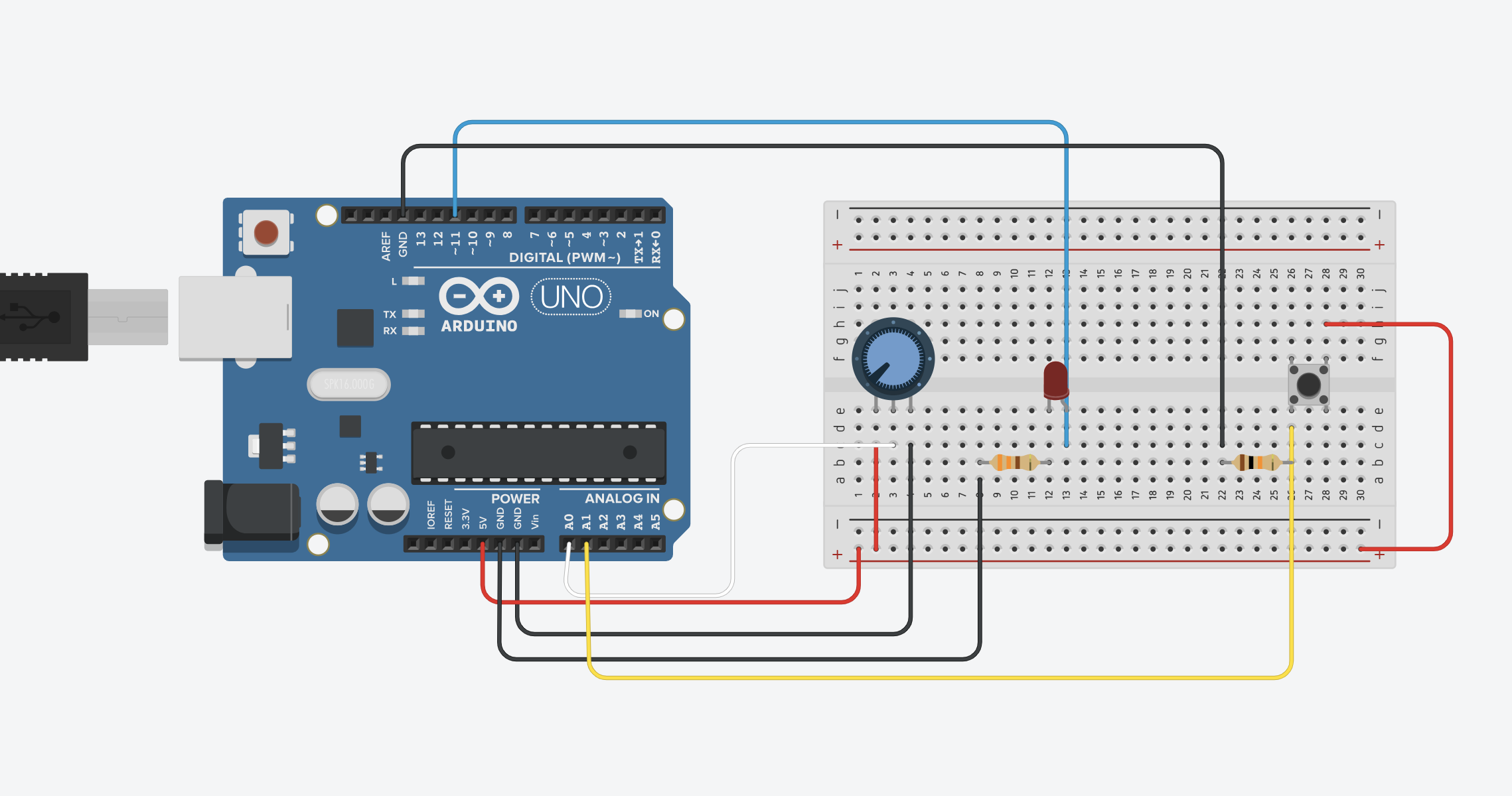
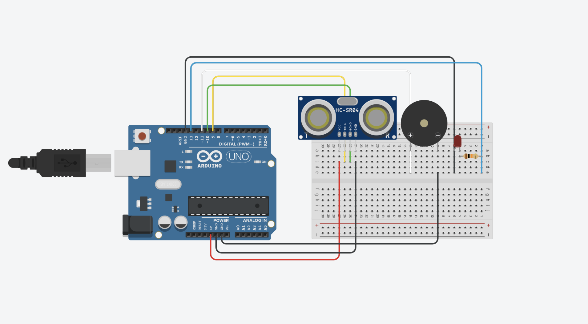
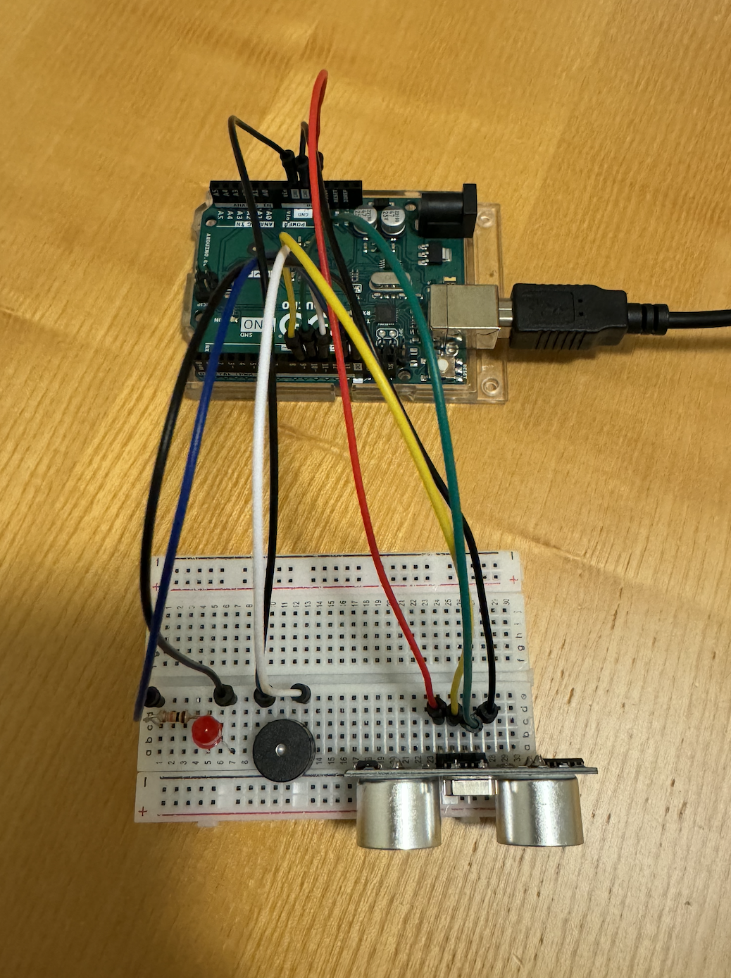
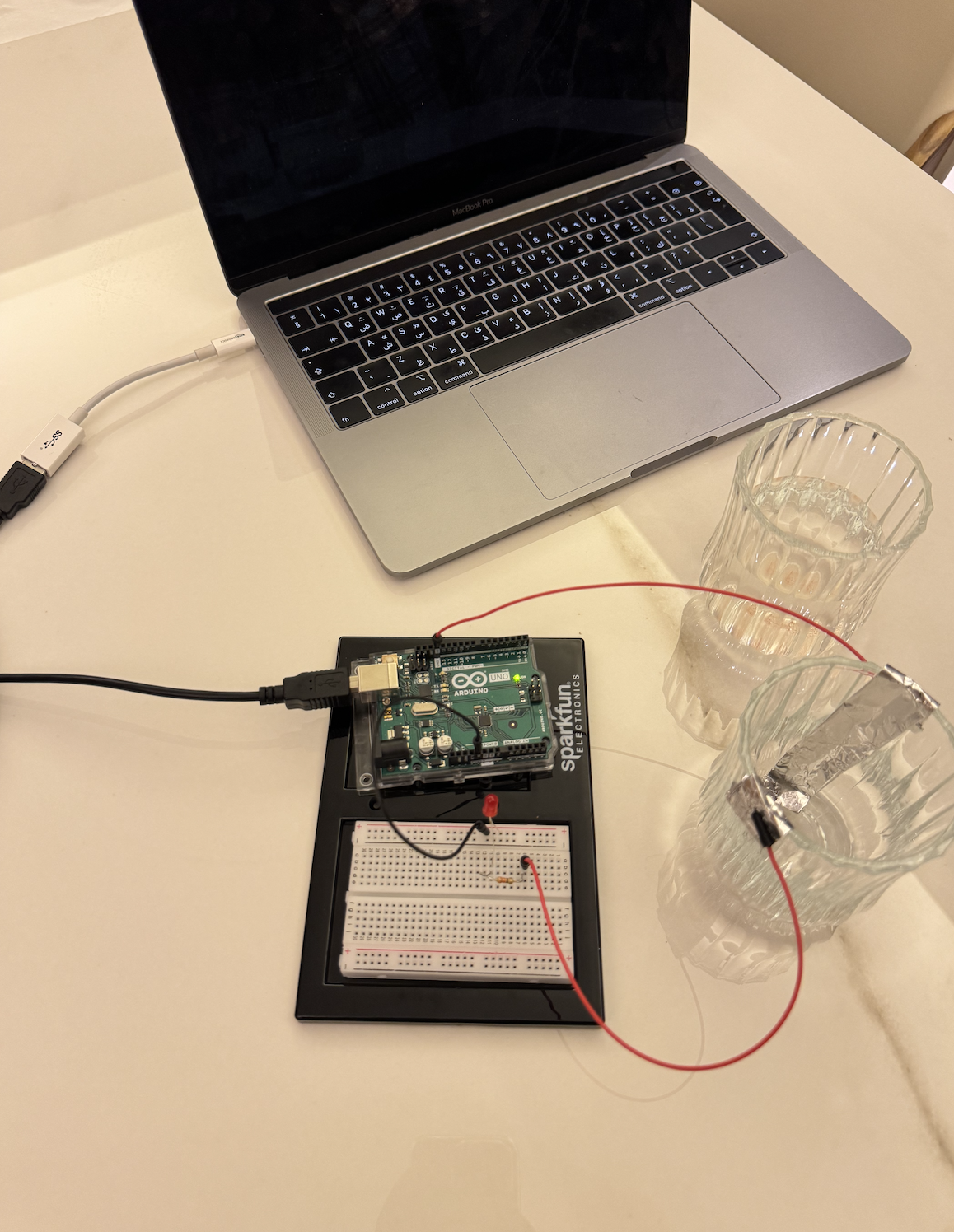
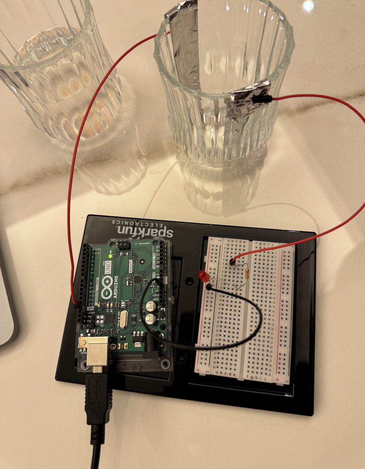
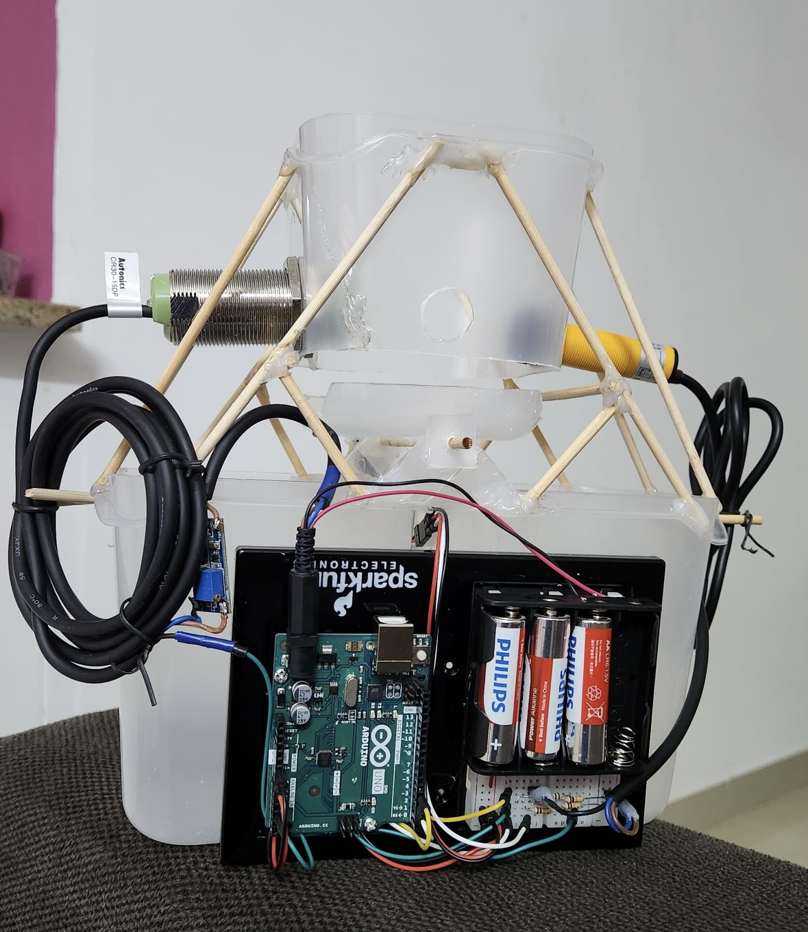
Images of the project:
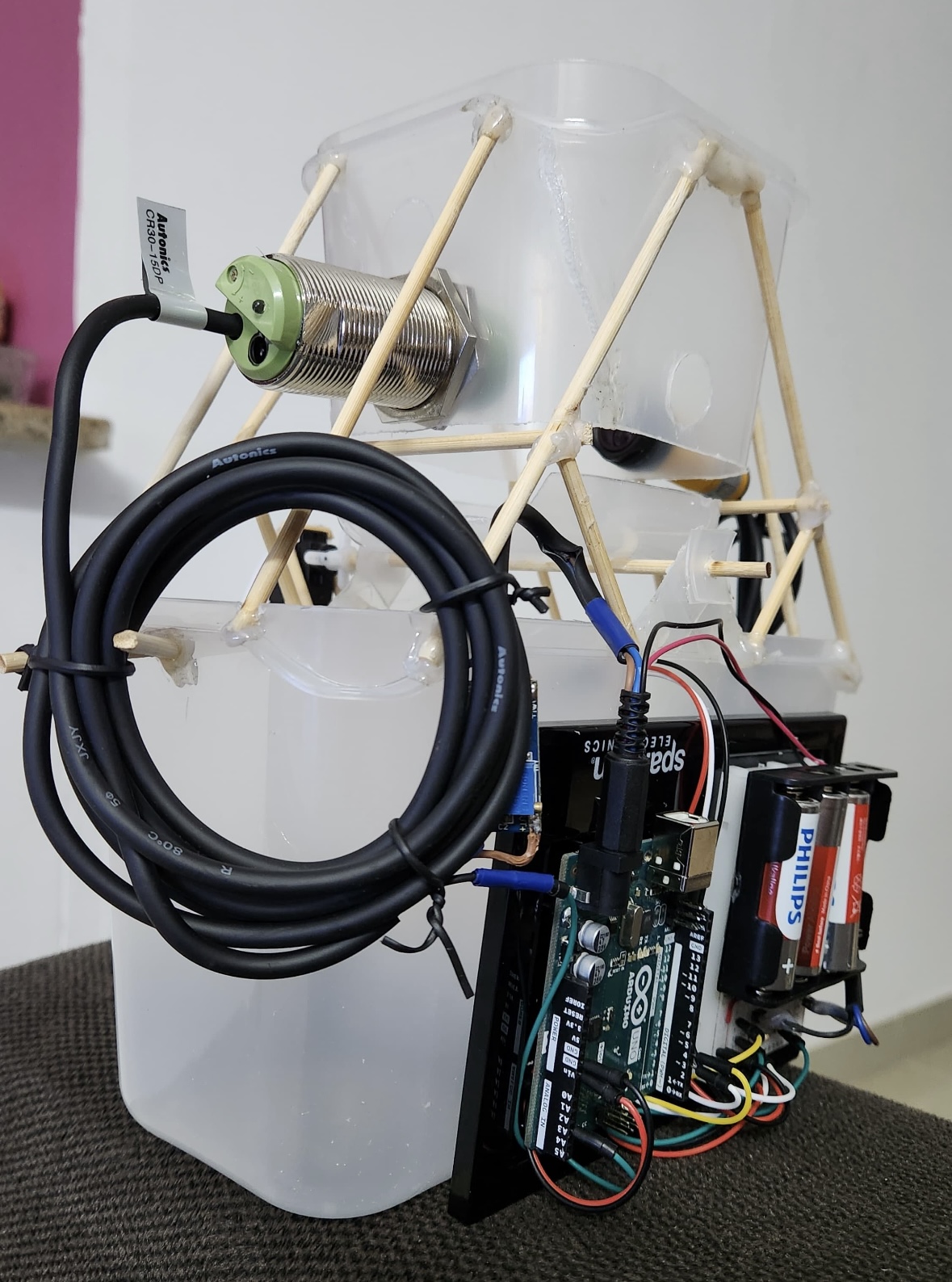
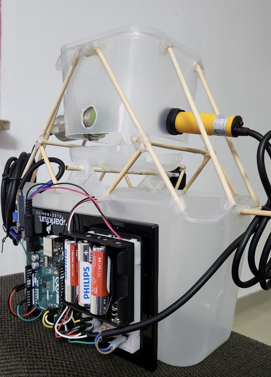
 

Components: 

Arduino uno

battery with 6 volts

IR sensor: E18-D80NK Adjustable Infrared Sensor

Capacitive sensor: Autonics Proximity Sensors Capacitive Sensors CR30-15DN

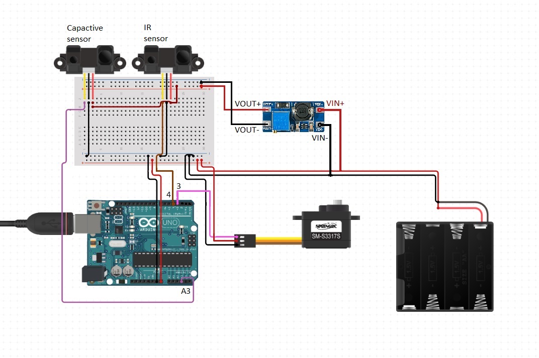
DC to DC boost converter : (the dc to dc boost converter employing a switching circuit and energy storage components like inductors and capacitors, increases the input voltage to a higher level through controlled switching and energy transfer processes.)
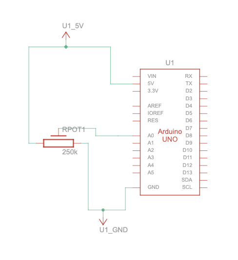
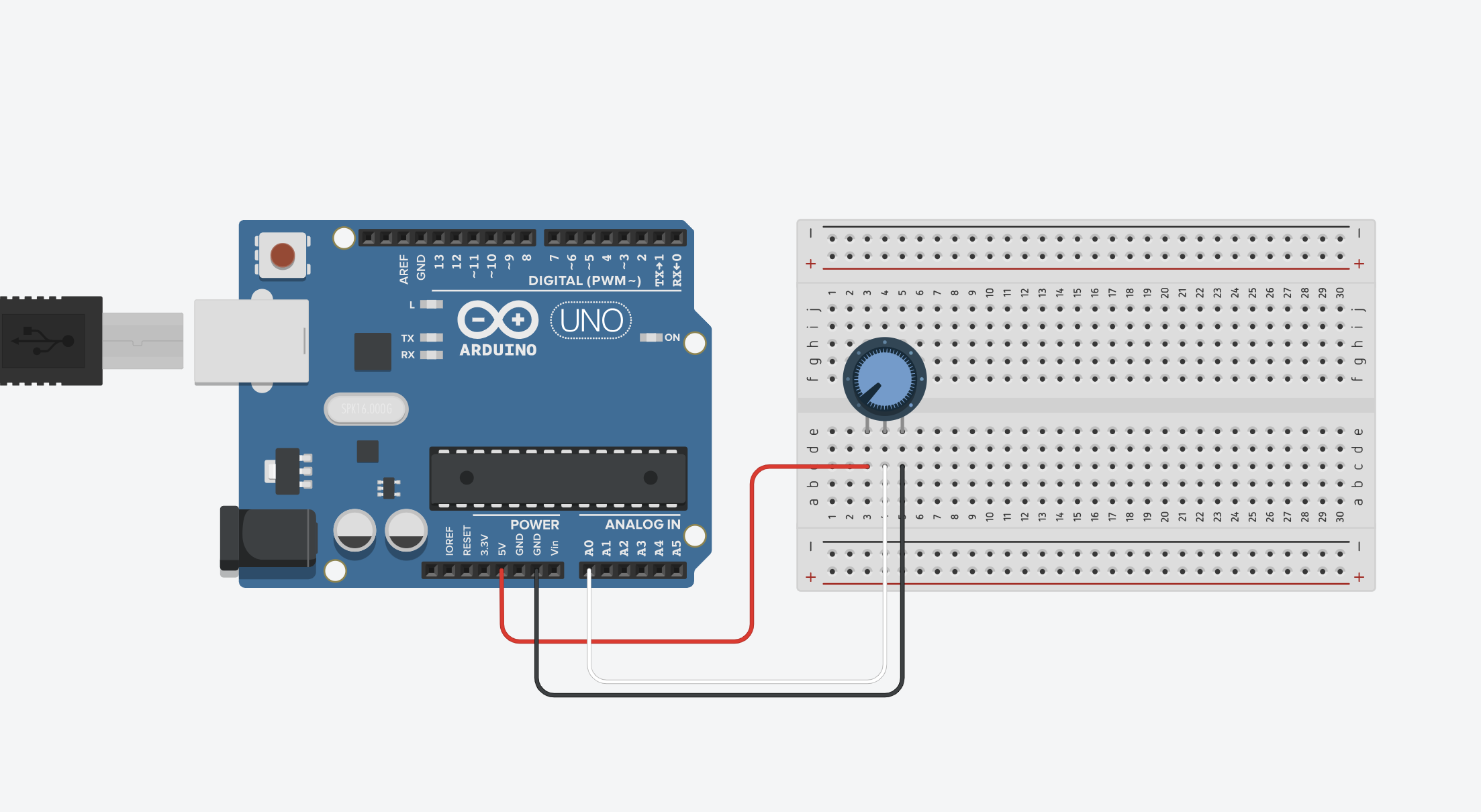
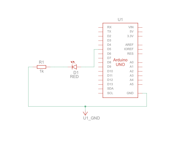
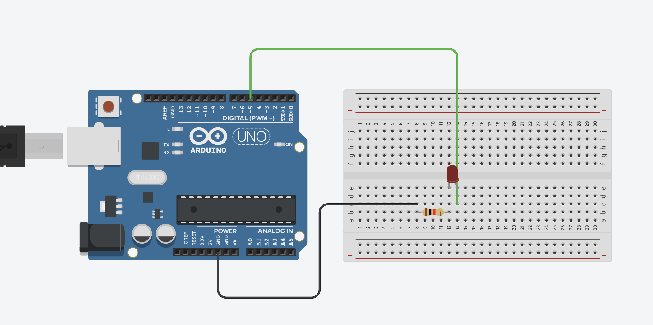
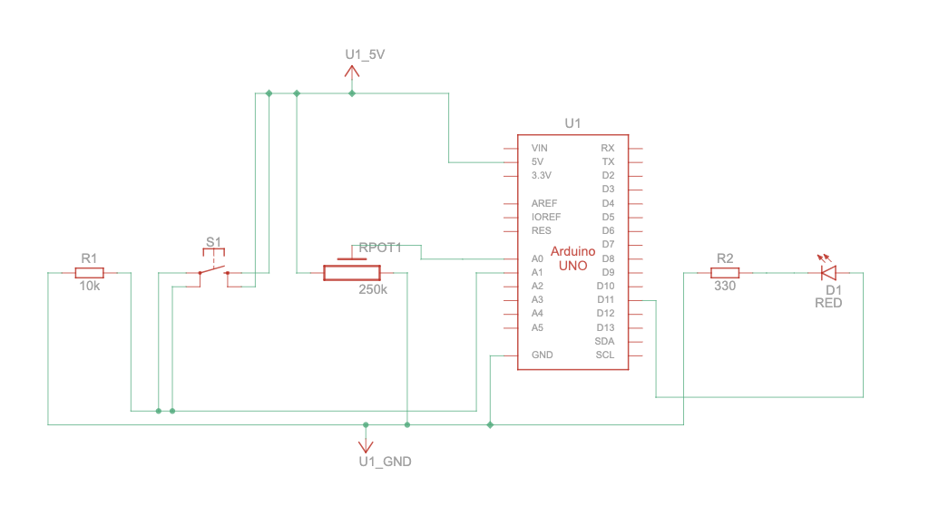
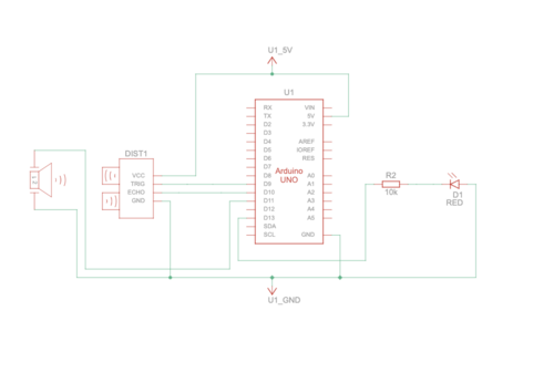
 

Schematic:

Videos:

User testing

How does the implementation work?

The project’s implementation consists of a smart system that uses technology to make things work. It uses an Arduino and P5.js . The Arduino has a special sensor called a capacitive sensor, which can figure out what kind of material something is made of. For example, it can tell if it’s plastic or something else. Additionally, there’s another sensor called an IR sensor. This sensor can figure out if there’s something in the trash bin or not. To make it even more useful, the project also has a web interface made with p5.js. Where you can control and change how the system works. It’s like having a remote control for your TV but for this trash sorting system. So, with the web interface, you can tell the system what to do, like sorting the trash in different ways or turning it on and off. This makes it easier for people to use and control the system the way they want.

Sensors:

IR Sensor: (Digital)

The infrared sensor has 2 leds, one for sending the infrared light and the second for receiving it. So if there is an object in front of the sensor the light will be reflected from the object back to the sensor. The IR sensor detects if there is an object present or not but it doesn’t know the material of the object. If the signal is high it means there is no object and if its low means there is an object. 5 volts high and low 0 volts.

Capacitive sensor: (Digital)

Capacitive sensors- the change in electric field that can detect if there is an object or not (also depends on the sensitivity/distance). The purpose of capacitive sensor in this project is to detect if the object is not plastic, it can detect conductive objects. When the IR sensor detects an object then it checks the capacitive sensor if the voltage is high (10volts) then the object is general (conductive) if the voltage is low (0volts) then the object is plastic or inductive

Description of interaction design:

The interaction design of the system is all about how people can use and communicate with it. In this case, users can interact with the system through the p5.js web interface, which is like a control panel on a computer screen.

Inside this interface, there are buttons that you can click on. These buttons allow you to do different things. For example, there are buttons that let you choose how the system works, like whether it should do things automatically by itself (automatic mode) or if you want to control it yourself (manual mode). This is similar to choosing between letting a robot do a task for you or doing it with your own hands.

There are also buttons to tell the system what kind of material you’re putting in the trash. You can say if it’s plastic or something else (general waste). This helps the system know what to do with the trash.

To make things even clearer, the interface shows you text on the screen. This text tells you what mode the system is in and what kind of material it’s looking for. This way, you can always see and understand what the system is doing.

Description of Arduino code + code snippets:

The Arduino code uses Servo and defines the pins for capacitive and IR sensors. It reads incoming serial data, processes the angle value, and adjusts the servo accordingly. Modes (automatic/manual) and sensor readings are also handled.

Include the servo library and define the pins with required variable:

#include <Servo.h>;

Servo GateServo;

#define capSensor A3 //Pin A3 (analog)
#define irSensor 4 //Pin 4 (digital)
#define GateServoPin 3 // GateServo pin

bool openTrash = false;
bool autoMode = true;

//Plastic goes to angle 11
//General goes to angle 158
//The closing angle of the gate which is 85 degree
 
int initialServoPosition = 85;
int anglePlastic = 11;
int angleGeneral = 150;

int capValue;

unsigned long GateServoReturnTime = 0;
const unsigned long GateServoReturnDelay = 1000; // 1 seconds in milliseconds

Receive data from p5js via serial connection and extract the angle for plastic and general:

void loop()
{
  while (Serial.available() > 0) {
    // Read the angle value from serial
    String incomingData = Serial.readStringUntil('\n');

    //If the mode is manual enable controlling by the p5js panel
    if (!autoMode) {
      // Check if the incoming data starts with "angle:"
      if (incomingData.startsWith("angle:")) {
        // Extract the angle value from the incoming data
        int angleValue = incomingData.substring(6).toInt();
  
        // Process the angle value if it is within the valid range
        if (angleValue >= 11 && angleValue <= 158) {
//          Serial.println("Received angle: " + String(angleValue));
          // Set the GateServo angle
          GateServo.write(angleValue);
  
          // Reset the timer each time a valid angle is received
          openTrash = true;
          GateServoReturnTime = millis();
        }
      }
    }

Get the working mode from p5js panel and control the servo:

 if (incomingData.startsWith("Auto")) {
      autoMode = true;
//      Serial.println("Auto mode: " + String(autoMode));
    }
    else if (incomingData.startsWith("Manual")){
      autoMode = false;
//      Serial.println("Manual mode: " + String(autoMode));
    }
  }

  // Check if it's time to return the GateServo to 85 degrees
  if (millis() - GateServoReturnTime >= GateServoReturnDelay && openTrash) {
    openTrash = false;
    GateServo.write(initialServoPosition);
//    Serial.println("Trash Closed");
  }


Description of p5.js code + Embedded p5.js sketch: 

The p5.js code controls the web interface, buttons, and communication with Arduino. It displays the current mode, material type, and provides buttons for user interaction.

Description of communication between Arduino and p5.js:

Communication between Arduino and p5.js is achieved through the serial port. The p5.js script sends commands for mode setting and material type selection, and the Arduino reads and processes these commands, adjusting the servo and handling sensors accordingly.

The breakdown of the bidirectional communication:

1. p5.js to Arduino:

  • Sending Commands & Data: In p5.js, the serial.write(data) function is to send data to the Arduino. This data could be commands, sensor readings, or any other information needed to be sent to the Arduino.
  • Receiving in Arduino: On the Arduino side, the Serial.available() to check if there’s data available in the serial buffer. If data is available, the functions erial.readStringUntil(‘\n’) is to read and process the incoming data.

2. Arduino to p5.js:

  • Sending Data from Arduino: In Arduino code, the Serial.print(), Serial.println() send data back to the p5.js sketch over the serial port. This could be sensor readings, or any information needed to be visualized or processed in p5.js.
  • Receiving in p5.js: In the p5.js sketch ,the serial. on(‘data’, gotData) event to define a function (gotData) that will be called whenever new data is received. Inside this function, the incoming data will be processed.

What are some aspects of the project that you’re particularly proud of?

The seamless integration of hardware components, the user-friendly p5.js interface, and the efficient sorting mechanism underscores the project’s success in creating a functional and user-centric waste disposal system. These achievements not only enhance the user experience but also promote environmentally responsible waste management practices by automating the segregation process based on detected material types.

Challenges faced and how you tried to overcome them:

Challenges included sensor calibration, ensuring real-time communication between Arduino and p5.js, and optimizing the sorting algorithm.

    • Sensor Calibration and Accuracy:One of the primary challenges encountered during the project was ensuring accurate sensor readings for object detection. The capacitive and IR sensors required precise calibration to reliably distinguish between plastic and general waste. To address this, an extensive calibration process was undertaken, involving systematic adjustments to sensor thresholds, distances, and environmental conditions. Regular testing with a variety of objects helped fine-tune the sensor parameters, improving the overall accuracy of material classification.
    • Real-time Communication:Achieving seamless and real-time communication between the Arduino and the p5.js web interface was another significant challenge. Ensuring that commands were sent and received promptly without delays was crucial for responsive user interaction.

What are some areas for future improvement?

There are several exciting possibilities for future improvements to make the system even better and more efficient.

One area of improvement could focus on enhancing the sorting algorithm. Right now, the system can distinguish between plastic and general waste, but in the future, it could be trained to recognize and sort a wider range of materials. For example, it could learn to separate paper, glass, and metal items, increasing the effectiveness of recycling and reducing waste even further.

Another exciting advancement could involve implementing machine learning techniques. By integrating machine learning, the system could become even smarter when it comes to recognizing different objects accurately. This means it could become better at identifying and sorting items that might be tricky to distinguish using only sensors. Machine learning can help the system adapt and improve its performance over time, making it more reliable in sorting various materials.


IM Showcase :

The interactive media showcase was engaging and educational, and I gained a lot from everyone presenting there. It was a fun and enlightening experience. The highlight for me was a conversation with Professor Eva Mansour. She encouraged me to present my project to the Ministry of Climate Change and Environment in the UAE. She believes they would appreciate my project and sees potential for its implementation in the UAE.

Professor Mansour advised me on several key steps: firstly, to publish a paper outlining my project’s concept and findings; then, to seek funding for further development; and finally, to conduct extensive testing. She also emphasized the importance of design, suggesting improvements to enhance its appeal. Her insights have given me much to consider, and I’m hopeful about the possibility of implementing this project in the UAE.

Finally, a huge shoutout to Professor Aya for running such an incredible course. Thank you for your guidance and support, I appreciate it. Every step of the way, you were there, making the whole learning journey not just educational but really enjoyable too. Thank you! <3

testing students projects


Links to resources used:

Servo Library 

P5.js Reference 

Final Project Idea 2

Concept:

Create an automatic trash can that uses sensors to detect and sort different types of waste (plastic, paper, etc.) into separate compartments within the can. The system will utilize Arduino for hardware control and p5.js for a user interface to monitor and interact with the trash can.

Components:

  1. Arduino Uno
  2. Ultrasonic sensors or weight sensors to detect the type of waste being disposed of.
  3. Servo motors or stepper motors to control the compartments for different types of waste.
  4. P5.js for the user interface to monitor the trash can’s status and possibly interact with it.

Arduino (Outgoing Data):

Detecting and Sorting: Arduino reads sensor data to detect the type of material placed in the trash can. Based on this detection, it activates servo motors to sort the materials into their respective compartments.
Serial Communication: Once the material is detected and sorted, Arduino sends updates about the detected material type and sorting process status via the Serial connection.

p5.js (Outgoing Commands):

p5.js sends commands/instructions to the Arduino via the Serial connection, requesting the disposal of a particular type of waste.

Arduino (Incoming Commands):

Receiving Instructions: Arduino listens for incoming commands from p5.js through the Serial connection. It interprets these commands to initiate the disposal process.
Status Queries: Arduino responds to queries from p5.js by sending updates on the system status, like whether it’s ready to receive new commands or the current state of the sorting mechanism.

p5.js (Incoming Data):

Display and Feedback: p5.js receives data from Arduino about detected materials and system status.

Week 11- Reflection

The author states that in the past, people thought it’s best to hide disabilities when making things, and this gives a bad feeling. It doesn’t just hide a part of the person, but it might also make them feel like they should be embarrassed to show and talk about their disability, which is actually a part of who they are.

They give an example of making things for people with disabilities, like glasses. Glasses show how some people don’t follow the old way of thinking. There are many kinds and styles of glasses so people can choose what feels comfortable and looks nice to them. Nowadays some people even get glasses just because they like how they look even if they don’t need them to see better. But if we think about another thing they talked about, like a fake leg for someone who lost a leg, some people might think it doesn’t look good and hide it, even though it works fine. I really think this should change. No one should feel bad about having a disability.

I think that disability itself isn’t the primary challenge; rather, it’s the environment that often creates difficulties for individuals with disabilities. When surroundings lack accommodations or accessibility features it becomes harder for people with disabilities to navigate and participate fully. So by creating inclusive environments and removing barriers, we can empower individuals with disabilities to engage more effectively and comfortably in various aspects of life, promoting equality and inclusivity for all.

The last thing I want to say is that I agree that these things should be simple. The main point of making things for people with disabilities is to help them. The things should be easy for them to use without making them feel stressed.

Final Project Idea

For my final project I envision revolutionizing waste management with an innovative automatic trash can that transforms the way we sort and manage our garbage. Imagine a single, sleek unit that dynamically categorizes different types of waste on its own, eliminating the need for multiple bins and the hassle of manual sorting. This intelligent trash can intuitively detects and segregates various materials like plastic, paper, and general waste as items are discarded, streamlining the recycling process effortlessly.

The system operates seamlessly, leveraging advanced sensors to identify the composition of incoming waste in real time. As items are tossed in, the trash can harnesses its sensor network to recognize the material type, swiftly directing each piece to its designated compartment within the unit. With a smart sorting mechanism at play, the trash can effortlessly organizes and manages the disposal, making eco-conscious living incredibly convenient for users.

This isn’t just a mere disposal unit; it’s a sustainable innovation aimed at promoting efficient recycling practices in households and public spaces. The simplicity of tossing items into a single receptacle while knowing they’ll be automatically sorted for proper recycling is not just convenient—it’s a step towards a cleaner, greener future.

Week 11- Serial Communication

Exercise 1: ARDUINO TO P5 COMMUNICATION

Schematic

Circuit Diagram 

P5.js Code
We used the same example provided in class, however, we just added this part to the code:

function draw() {
  
  background('#6FA9B0')

  if (!serialActive) {
    fill("rgb(255,255,255)")
    text("Press Space Bar to select Serial Port", 20, 30);
  } else {

    noStroke()
    // draw a circle, alpha value controls the x-position of the circle
    circle(map(alpha, 0, 1023, 0, 640), 240, 50)

  }
}


Arduino

We used the same one provided in class.

Video


Exercise 2: P5 TO ARDUINO COMMUNICATION

Schematic

Circuit Diagram 

P5.js Code

let brightness = 0; 
let slider;
let img;

//preload images
function preload(){
  img = loadImage('sun.png');
  img2 = loadImage('moon.png');
}

function setup() {
  createCanvas(400, 400);
  //create slider
  slider = createSlider(0, 255, 100);
  slider.position(width/2-50,height/2+25);
  slider.style('width', '80px');
}

function draw() {
  background('#85CCEC');
  image(img,235,130,150,180); 
  image(img2,30,140,100,160);
  
  let val = slider.value();
  brightness = val;
  
  // instructions
  textAlign(CENTER,CENTER);
  textSize(16);
  textStyle(BOLD)
  text("Control the brightness using the slider below!",width/2,100);
  
  //connects serial port
  if (!serialActive) {
    textSize(10);
    text("Press Space Bar to select Serial Port", 100, 30);
  } else {
    textSize(10);
    text("Connected",100,30);
  }


}

function keyPressed() {
  if (key == " ") {
    // important to have in order to start the serial connection!!
    setUpSerial();
  }
}


function readSerial(data) {

  //READ FROM ARDUINO HERE
  
  if (data != null) {
    // if there is a message from Arduino, continue
    
    //SEND TO ARDUINO HERE (handshake)
    
    let sendToArduino = brightness + "\n";
    writeSerial(sendToArduino);
  }
}


Arduino Code

int LED = 5;
void setup() {
  Serial.begin(9600);
  pinMode(LED, OUTPUT);
  // start the handshake
  while (Serial.available() <= 0) {
    Serial.println("Wait");  // send a starting message
    delay(300);               // wait 1/3 second
  }
}
void loop() {
  // wait for data from p5 before doing something
  while (Serial.available()) {
    int brightness = Serial.parseInt(); 
    if (Serial.read() == '\n') {
      analogWrite(LED, brightness); // turn on LED and adjusts brightness
      Serial.println("LIT"); 
    }
  }
}


Video

Exercise 3: BI-DIRECTIONAL COMMUNICATION

Schematic

Circuit Diagram 

P5.js Code

let hit = 0;  // whether the ball hit the ground
let reset = 0;  // whether Arduino sent a reset argument (a button press)

// Ball physics
let velocity;
let gravity;
let position;
let acceleration;
let wind; // wind direction is controlled by Arduino (potentiometer)
let drag = 0.99;
let mass = 50;

function setup() {
  createCanvas(600, 600);
  noFill();
  position = createVector(width / 2, 0);
  velocity = createVector(0, 0);
  acceleration = createVector(0, 0);
  gravity = createVector(0, 0.5 * mass);
  wind = createVector(0, 0);
}

function draw() {
  background('pink');
  applyForce(wind);
  applyForce(gravity);
  velocity.add(acceleration);
  velocity.mult(drag);
  position.add(velocity);
  acceleration.mult(0);
  fill(255)
  ellipse(position.x, position.y, mass, mass);
  if (position.y > height - mass / 2) {
    velocity.y *= -0.9; // A little dampening when hitting the bottom
    position.y = height - mass / 2;
    hit = 1;
  } else {
    hit = 0;
  }

  if (!serialActive) {
    console.log("Press Space Bar to select Serial Port");
  } else {
    // 
    // console.log("Connected");
    if (reset == 1) { // if reset signal is sent and flagged (button press)
      reset = 0; // clear the flag
      
      // reset ball with some random mass
      mass = random(15, 80);
      position.x = width / 2;
      position.y = -mass;
      velocity.mult(0);
    }
  }
}

function applyForce(force) {
  // Newton's 2nd law: F = M * A
  // or A = F / M
  let f = p5.Vector.div(force, mass);
  acceleration.add(f);
}

function keyPressed() {
  if (key == " ") {
    // important to start the serial connection!
    setUpSerial();
  }
}

function readSerial(data) {
  
  //READ FROM ARDUINO HERE
  

  if (data != null) {
    // split the message
    let fromArduino = split(trim(data), ",");
    // if the right length, then proceed
    if (fromArduino.length == 2) {
      reset = fromArduino[0];
      wind.x = fromArduino[1];
    }

    
    //SEND TO ARDUINO HERE (handshake)
    
    let sendToArduino = hit + "\n";
    writeSerial(sendToArduino);
  }
}


Arduino Code

int buttonSwitch = A2;
int potentiometer = A0;
int ledOut = 11;

void setup() {
  Serial.begin(9600);
  pinMode(12, OUTPUT);
  digitalWrite(ledOut, LOW);  // in the case of reconnection while p5 is running
  // start the handshake
  while (Serial.available() <= 0) {
    Serial.println("-1,-1");  // send a starting message
    delay(300);               // wait 1/3 second
  }
}

void loop() {
  // wait for data from p5 before doing something
  while (Serial.available()) {
    int hit = Serial.parseInt(); // receives 1 argument, whether the ball hit the ground
    if (Serial.read() == '\n') {
      digitalWrite(ledOut, hit); // turn on LED if the ball is in contact with the ground (1 -> HIGH) turn off LED if not (0, -> LOW)
      int sensor = digitalRead(buttonSwitch); // read button
      delay(1);
      int sensor2 = analogRead(potentiometer); // read potentiometer
      delay(1);
      Serial.print(sensor); // button
      Serial.print(',');
      if (sensor2 < 512) { // potentiometer; depending whether the value is over or below half, direction of the wind is set
        Serial.println(1);
      } else {
        Serial.println(-1);
      }
    }
  }
}


Video

Week 10- Reflection

In his blog post “A Brief Rant on the Future of Interactive Design,” Bret Victor talks about the need to create a dynamic medium that people can interact with in a way that’s similar to how they interact with physical objects. What really struck me was his point that the technology behind tablets, smartphones, and other similar devices, known as Pictures Under Glass, doesn’t offer genuine touchable interfaces. Victor believes that technologies that prioritize sleek visuals over tactile experiences are just a passing phase. 

The first post and the follow-up response both emphasize that researchers and developers should look into haptic feedback to make devices easier to use. I agree with the author’s concerns about the future of interaction design. Touchscreens are great, but they’re not the only way to interact with computers. We need to explore new technologies that let us interact with computers in a more natural and intuitive way, like haptic feedback. Haptic feedback can make our interactions with computers more immersive and engaging. Imagine feeling the texture of a virtual object or manipulating it with your hands. That would be pretty cool. But we shouldnt ignore other forms of interaction, like voice or visual cues. Instead, we should find ways to combine different interaction methods to create the best possible user experience.

Week 10- EchoGuard: Your Personal Parking Assistant

Concept

Our assigment idea was sparked by a common scenario we all encounter – parking a car in reverse. In discussing the challenges of accurately judging the distance, my partner and I realized the potential hazards and the lack of a reliable solution. Considering how much we rely on the beeping sensor in our own cars for safe parking, we envisioned a solution to bring this convenience to everyone. Imagine a situation where you can’t live without that reassuring beep when you’re reversing. That’s precisely the inspiration behind our assigment – a beeping sensor and a light that mimics the safety we’ve come to depend on, implemented with a car toy to illustrate its practical application.

Required Hardware

– Arduino
– Breadboard
– Ultrasonic distance sensor
– Red LED
– 10k resistor
– Piezo speaker
– Jumper wires

Schematic Diagram:

Circuit Diagram:


Setting Up the Components

Ultrasonic Distance Sensor Connections:
VCC to 5V
TRIG to digital pin 9
ECHO to digital pin 10
GND to GND on the Arduino

Speaker Connections:
Positive side to digital pin 11
Negative side to GND

LED Connections:
Cathode to GND
Anode to digital pin 13 via a 10k resistor

Coding the Logic

// defines pins numbers
const int trigPin = 9;
const int echoPin = 10;
const int buzzerPin = 11;
const int ledPin = 13;

// defines variables
long duration;
int distance;
int safetyDistance;

// Define pitches for the musical notes
int melody[] = {262, 294, 330, 349, 392, 440, 494, 523}; 

void setup() {
  pinMode(trigPin, OUTPUT); // Sets the trigPin as an Output
  pinMode(echoPin, INPUT);  // Sets the echoPin as an Input
  pinMode(buzzerPin, OUTPUT);
  pinMode(ledPin, OUTPUT);
  Serial.begin(9600); // Starts the serial communication
}

void loop() {
  // Clears the trigPin
  digitalWrite(trigPin, LOW);
  delayMicroseconds(2);

  // Sets the trigPin on HIGH state for 10 microseconds
  digitalWrite(trigPin, HIGH);
  delayMicroseconds(10);
  digitalWrite(trigPin, LOW);

  // Reads the echoPin, returns the sound wave travel time in microseconds
  duration = pulseIn(echoPin, HIGH);

  // Calculating the distance
  distance = duration * 0.034 / 2;

  safetyDistance = distance;
  if (safetyDistance <= 5) {
    // Play a musical note based on distance
    int index = map(safetyDistance, 0, 5, 0, 7); // Map distance to array index
    tone(buzzerPin, melody[index]); // Play the note
    digitalWrite(ledPin, HIGH);
  } else {
    noTone(buzzerPin); // Stop the tone when not close
    digitalWrite(ledPin, LOW);
  }

  // Prints the distance on the Serial Monitor
  Serial.print("Distance: ");
  Serial.println(distance);
}


Hardware Implementation:


Video Illustration:

Video Illustration 2 (using melody)

Working Explanation and Conclusion
The ultrasonic distance sensor measures the gap between the car and the sensor on the breadboard. When the distance diminishes below a predefined threshold (5 units in our design), the buzzer emits a warning sound, and the red LED illuminates, acting as a clear visual cue for the driver to halt. This Arduino-based system seamlessly combines hardware and software, offering an elegant solution to a common problem. In creating this assignment, we’ve not only simplified the process of reverse parking but also contributed to enhancing overall safety, turning our initial conversation into a tangible, practical innovation.

Week 9- Sunset Effect

Concept:

The concept involves creating an Arduino-based project that combines analog and digital sensors to control two LEDs in a creative way.  The goal is to simulate a sunset effect using the LDR to detect ambient light levels. The system uses the button to sequentially turn on two LEDs and the potentiometer to adjust the brightness, providing a visually appealing sunset simulation.

Sunset Simulation Sequence:

    1. Initialization:
      • Upon activation, both yellow and red LEDs light up simultaneously, representing the starting point of the sunset effect.
    2. First Button Press:
      • When the button is pressed for the first time, the yellow LED dims or turns off, symbolizing the initial phase of the sunset where daylight begins to fade.
    3. Second Button Press:
      • Upon another press of the button, the red LED dims or turns off, indicating the advanced stage of the sunset where the sky adopts warmer hues.
    4. Potentiometer Control:
      • Throughout the simulation, the potentiometer allows users to adjust the overall brightness, offering a real-time customization of the sunset effect.

https://youtu.be/DqOrlSnHzus

Code: 

const int buttonPin = 2;     // Pin number for the push button (connected to ground with pull-up resistor)
const int led1Pin = 3;       // Pin number for the first LED
const int led2Pin = 5;       // Pin number for the second LED
const int potPin = A0;       // Pin number for the potentiometer

int buttonState = HIGH;      // Variable to store the current state of the button
int lastButtonState = HIGH;  // Variable to store the previous state of the button
int led1State = LOW;         // Variable to store the state of the first LED
int led2State = LOW;         // Variable to store the state of the second LED
int potValue = 0;            // Variable to store the potentiometer value
int brightness = 0;          // Variable to store the LED brightness
int flag = 0;

void setup() {
  pinMode(buttonPin, INPUT_PULLUP);
  pinMode(led1Pin, OUTPUT);
  pinMode(led2Pin, OUTPUT);
}

void loop() {
  buttonState = digitalRead(buttonPin);

  // Check if the button is pressed (LOW) and was not pressed before
  if (buttonState == LOW && lastButtonState == HIGH) {
    // Toggle the state of the first LED
    led1State = !led1State;
    digitalWrite(led1Pin, led1State);

    // If the first LED is turned on, wait for the second button press to turn on the second LED
    if (led1State == HIGH) {
      delay(50); // Debounce delay
      buttonState = digitalRead(buttonPin);
      if (buttonState == LOW) {
        // Toggle the state of the second LED
        led2State = !led2State;
        digitalWrite(led2Pin, led2State);
        flag = 1;
      }
    }
  }

  if (flag == 1) {
    // Read the potentiometer value and map it to the LED brightness range (0-255)
    potValue = analogRead(potPin);
    brightness = map(potValue, 0, 1023, 0, 255);

    // Apply the brightness to both LEDs
    analogWrite(led1Pin, led1State ? brightness : 0);
    analogWrite(led2Pin, led2State ? brightness : 0);
  }

  // Save the current button state for the next iteration
  lastButtonState = buttonState;
}


Improvements:

For future upgrades, I want to make the lights in my project more interesting by creating complex patterns. I’m thinking of making the sunset simulation more dynamic and captivating with intricate lighting sequences inspired by nature. Also, I’d like to get better at drawing schematics.

Week 9- Reading Response

In his blog posts, Tom Igoe analyzes the importance of innovative thinking for those who work on physical computing projects and considers the performative dimension of digital products and creative artworks. What strikes me about his approach is that Igoe encourages students to stop thinking of specific ideas as not original and consider how to create variations of them instead. While dance floor pads, electronic instruments controlled by players’ gestures, and touch kiosks may seem overused, such projects bring about a wealth of learning opportunities. Interactive art projects enable creators to engage their audience and discover new interpretations.

Instead of scripting users’ actions, creators should prioritize giving them the freedom to express themselves through works of art. I find this strategy especially useful for product developers, artists, and creative professionals looking for ways to grab the interest of their audience. As it is impossible to predict how a target user may react to an end product without conducting thorough research, we can test out physical computing and creative art projects in real time to get feedback. I think that by analyzing users’ and viewers’ reactions, web developers and artists can increase the value of their projects.

Week 8 – Saltwater Conductivity

For this assignment, I setup a cup of saltwater with two wires connecting to two aluminum foils, which were positioned in an empty cup. Next, I configured the Arduino board, connecting an LED to the breadboard along with a resistor. Powering up the Arduino with the computer, we poured the saltwater into the empty cup. As the saltwater facilitated the flow of current between the electrodes, the circuit was completed, and the LED was activated.

Saltwater lights up the LED by serving as a conductive medium that allows the flow of electricity. When the salt dissolves in the water, it separates into positively and negatively charged ions, making the water conductive. As the two electrodes, placed in the saltwater, complete the circuit, the flow of current is facilitated through the saltwater. This flow of electricity activates the LED, causing it to emit light. The presence of the salt enables the completion of the electrical pathway, allowing the LED to be powered and produce illumination.

https://youtube.com/shorts/xvapKBzMCXU?feature=share

One practical application of the saltwater conductivity experiment could be in the field of emergency lighting systems. In remote or disaster-prone areas where access to conventional power sources is limited, this saltwater-based circuit could serve as an emergency lighting solution. For instance, in regions prone to natural disasters such as hurricanes or earthquakes, where power outages are common, individuals could use this simple saltwater-powered LED setup as an alternative lighting source. This cost-effective and simple solution could significantly contribute to enhancing safety and visibility in challenging circumstances where traditional power sources are unavailable.