Final Project Documentation

Concept of Project

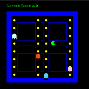
I decided for the final project to design a game that is very similar to the maze action video game, Pacman. Therefore, the main concept of my game is that there is a main character that looks like a green arc who tries to avoid the ghost enemies and eat circles, the more circles the character eats the more points he gets. The player will win the game if he or she can eat fifteen circles before bumping into one of the ghosts. On the other hand, if one of these ghosts catches the player before reaching a score of 15 circles eaten, then the player will lose the game.


I decided to create a game with this concept because I enjoyed playing Pacman as a kid and wanted to explore if I might be able to make a game that is very similar to my favorite childhood game. To make this project even more interesting, I decided to change some of the instructions of the normal Pacman game. If the main player eats a circle, the circle should change colors from yellow to red. Moreover, the main player can eat a circle more than one time.

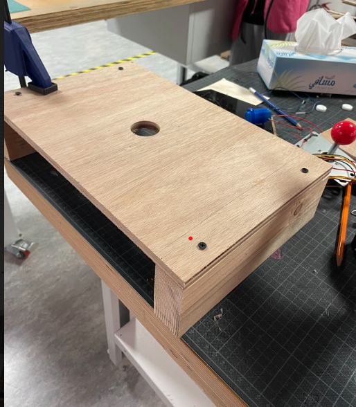
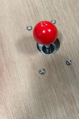
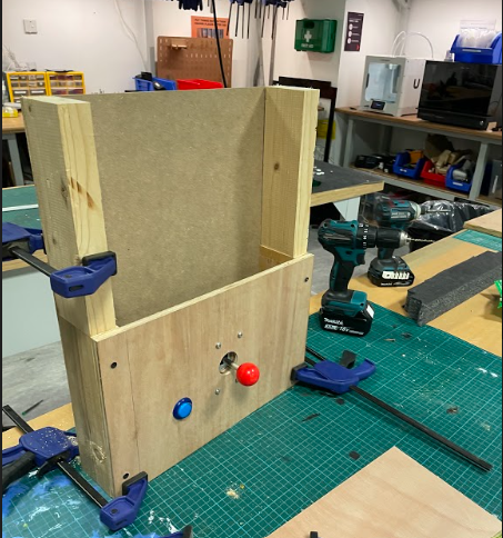
This design for the game was implemented in my midterm project. For the final project, I decided to add more stuff to this game and make it controllable using hardware devices. Therefore, I created a physical structure that contains the hardware devices which control the Pacman game. These devices mainly include a joystick and a button and you can see the final output in the video below.

Description of Interaction Design

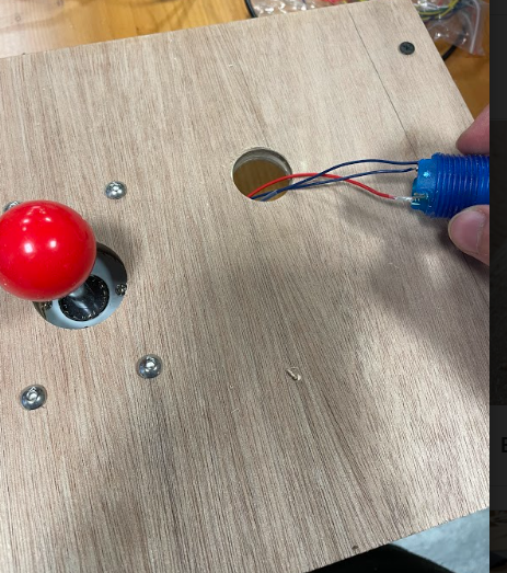
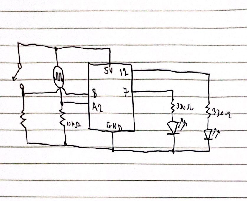
The interaction between the user and the game using hardware was done using mainly a joystick and a button. At first, the user will only see the main menu screen of the game that you can see attached below.

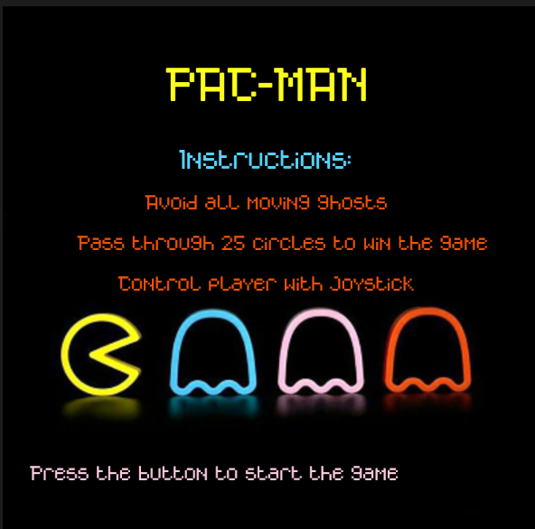
By pressing on the blue button that you can see in the image of the physical structure above, the user can start the game and move to the screen where the play screen of the game that you can see below.

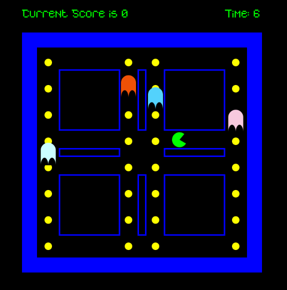
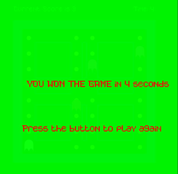
After that, the user can use the joystick to control the motion of Pacman in the game. By moving the joystick to the left PacMan will move to the left, while moving it to the right PacMan will move to the right, by moving the joystick forward PacMan will move up and by moving the joystick backward PacMan will move down. With this control of the PacMan motion the user can play the game easily and smoothly and enjoy one of the most famous classic arcade games. When the user win the game by reaching the score of 255 they will see the following screen

However, when the user loses the game they will see the following screen


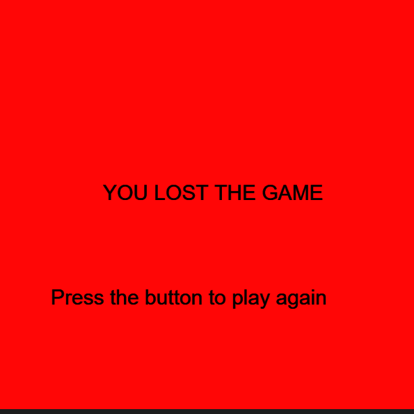
By just pressing the blue button the user will be able to restart the game again.

Description of Arduino Code

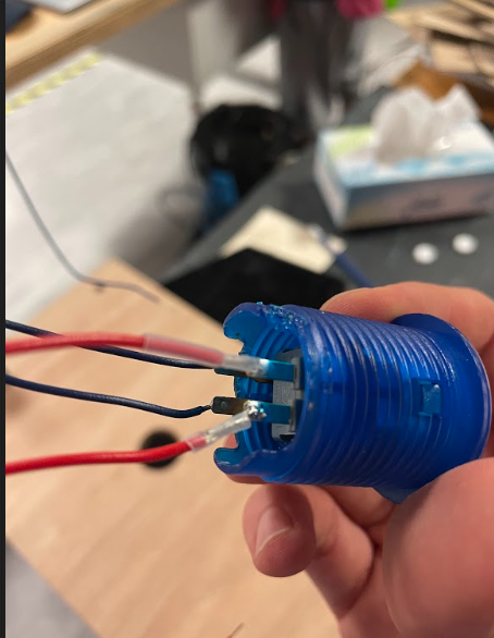
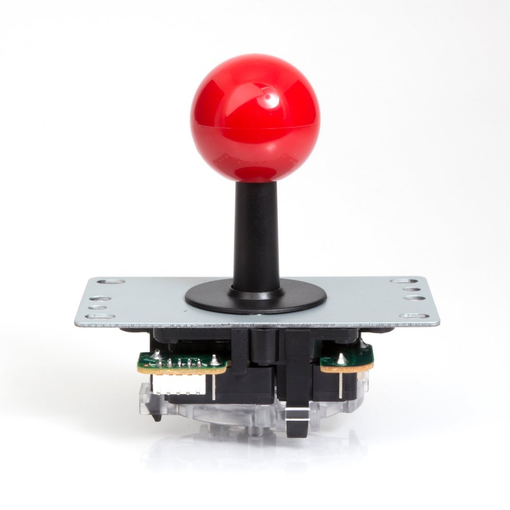
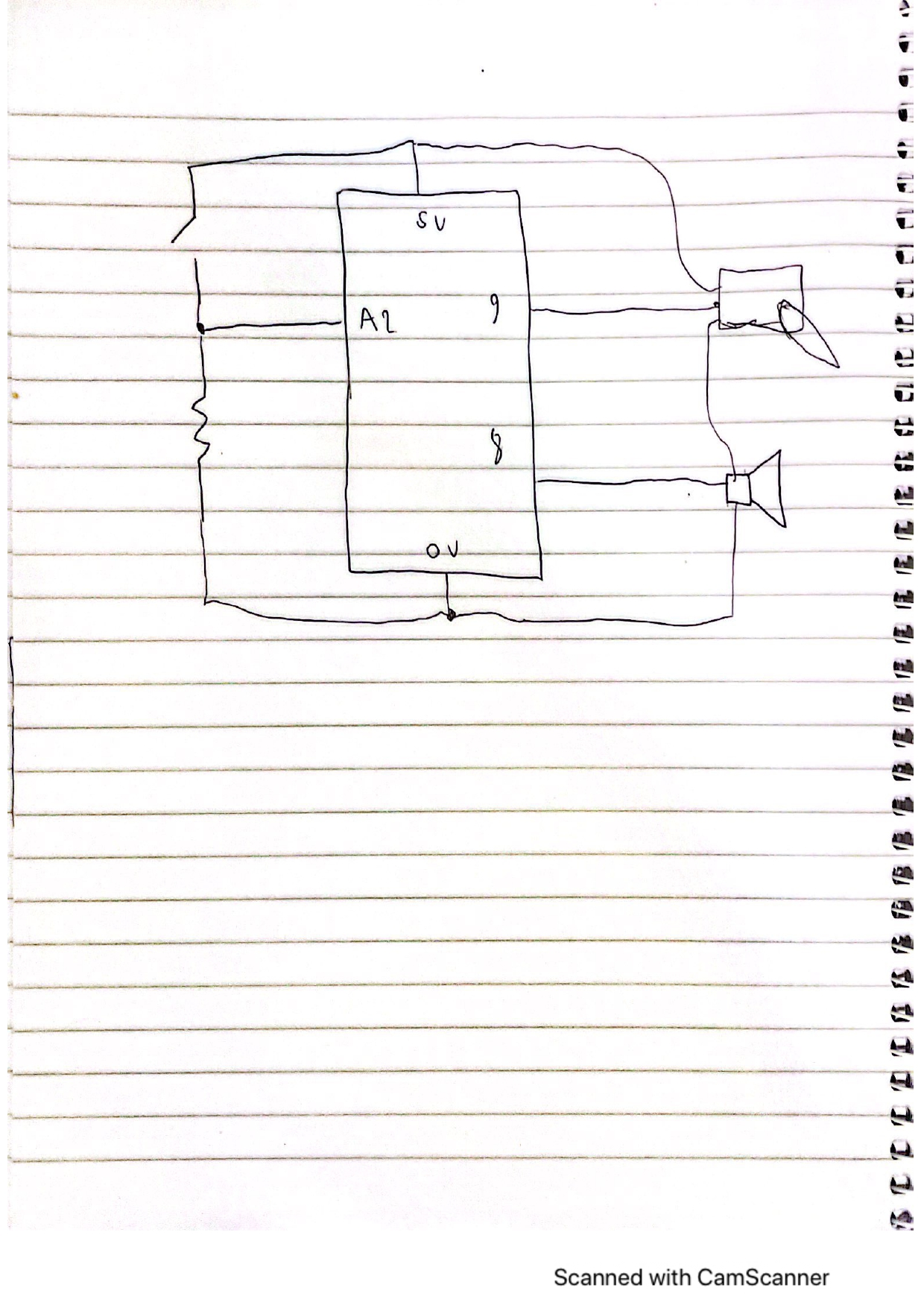
The Arduino code for my final project is designed to control the joystick and the button in my game. I initialized four different pins that the Arduino code will read based on the inputs from the joystick. This is because the joystick that I am using has five different wires. One wire is connected to the ground while the other four wires are responsible for detecting the motion of the joystick in four different directions, forward, backward, left, and right. Therefore as you can see in this section of my Arduino code I am reading the values of these four different pins in Arduino. I decided to use the pull-up resistor when defining these pins to ensure that the pins are all set to 1 whenever the switch is turned off.

void loop() {
  
  switchState=digitalRead(12);

  UP = digitalRead(upPin);
  RIGHT = digitalRead(rightPin);
  LEFT = digitalRead(leftPin);
  DOWN=digitalRead(downPin);
  
  Serial.print(UP);
  Serial.print(',');
  Serial.print(DOWN);
  Serial.print(',');
  Serial.print(RIGHT);
  Serial.print(',');
  Serial.print(LEFT);
  Serial.print(',');
  Serial.println(switchState);
  delay(100); // add some delay between reads
}

Furthermore, I read another value in the Arduino code which is the value of the blue button to determine the state of the switch at any time. After that, I print the values of the four joystick pins as well as the value of the blue button and separate them by commas to send them to p5.js. I added delay between the reads to ensure that there is no unnecessary errors due to fast reads.

Description of P5.js code

The p5.js code contains information about the pacman game. It contains four main states which are the main menu, play state, win and loss states. I showed images of these states above, and to move from one state to another I created a state machine. To come up with the pacman and ghosts in the game I used two different classes. Inside the pacman class I created some functions to draw the pacman, move the pacman and check if the pacman hits any of the boundaries that I draw on the screen.

To create the ghosts in the game I created another class called ghost, in this class I also created functions to draw the ghosts and place them in random positions and move them up and down. I also control the speed of the ghosts in this class. After that, I created a function that detects whenever the pacman hits one of the ghosts to detect when the user is supposed to move to the loss state. I show the code for calling these functions in the playscreen below.

  for (let k = 0; k < 4; k++) {
    ghost[k].moveEnemy();
    ghost[k].checkBounds();
    ghost[k].drawEnemy();
    //check if the main player will hit the enemy
    ghost[k].checkLossState(mainCharacter.xPos, mainCharacter.yPos);
  }
  //draw main character and call different functions of the class
  mainCharacter.drawPlayer();
  currTime = int((millis() - prevTime) / 1000);
  textSize(15);

  text("Time: " + currTime, 300, 30);

  mainCharacter.checkBoundsConditions();
  mainCharacter.movePlayer();
  mainCharacter.eatCircles();
  mainCharacter.displayCount();

  mainCharacter.checkWinningState();
}

Communication between Arduino and p5.js

P5.js should also read 4 different values from arduino which will be the UP position, DOWN position, LEFT position and RIGHT position. If any of these values is zero then in p5.js I will write if statements to move the pacman towards this direction. For instance, if UP is zero then pacman moves towards the up direction.

In addition to this, the p5.js program will read another value from Arduino which will be the current state of the blue button. If the button is pressed, then in the p5.js I can move from one game state to another. For example, if I am in the main menu screen and would like to move to the game screen then I can easily do this by just pressing the blue button.

As a result, in the Arduino part of my project, I will be writing to the serial the 5 different values that I want to send to p5.js which are the four different directions along with the switch state and will separate these values by commas so that they could be easily read in p5.js. I display below the finalized version of my game with sounds implemented in it.

What are some aspects of the project that you’re particularly proud of?

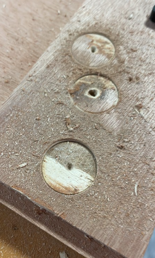
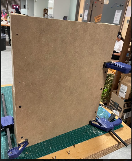
This project especially the hardware and the physical computing part of it was very challenging for me. I spent so much time drilling wood and connecting wooden pieces together, therefore I think that the most challenging part of my project is mainly building the physical structure to house the different hardware devices. Although it was not easy, I am very proud of the result that came out of it because I really like how it looks right now and you can see it in the video that I attached above. Furthermore, I discuss in detail how I came out with this output in my previous post which shows the progress towards my final project.

What are some areas for future improvement?

I believe that I could add more hardware stuff to the game in the future. I would be adding some indicators like LED lights that will display to the user their progress in the game. For instance, if the user needs 25 points to win the game, I will have 5 LED lights and each LED light will light up after the user obtains 5 points. So after the user get the 25 points, he will have the 5 lights all being on.

Furthermore, I would also like to improve more on the software part of the game. This will be done by making the yellow circles disappear when the user goes over them. This will avoid having a glitch in the game where the user can go over the same yellow circle multiple times and still win the game. Overall, I really enjoyed this project and believe that I learned so much from it. I hope I can design more creative things with this knowledge in the future.


Final Project Progress

During the past week, I spent most of the time working on the physical structure of my project because this was the most confusing part for me and I did not have any experience with using wood and drilling stuff on wood. After going through a long process of cutting wood, drilling holes into the wood, then adding screws between wooden pieces using different drill bits, I was finally able to almost complete my physical structure and house the different devices inside my wooden building. In this blog I will demonstrate the different stages I went through to achieve the desired output.

The professor at first helped me with cutting three wooden pieces, one large piece that is placed on top of the two other pieces. After that, the professor also helped me in drilling a big hole in the middle of the wood to attach the joystick to it. Then I had to use the drill for the first time to drill four different holes on the sides of the big wooden piece and on the two other wooden pieces. To find the place where I am supposed to drill the holes I used a pencil and a ruler, then I used drill bits with size of 5mm to screw the 5mm screws in my wooden structure, I was able to get the following output from this step.

Then after that I was able to attach the joystick to this physical structure by using the four of the following type of bolts. I also attached nuts to these bolts to keep them in place. I tested the joystick after that and made sure that it is tightly fit in place.

After that I also wanted to make the game more interactive and decided to add a blue butto to allow the user to control the game. To add this button I had to solder stranded wires onto the button. Then I had to solder these stranded wires to solid wires so that I can attach them to the breadboard.

To add the blue button to my physical structure I had to drill another hole on top of my physical structure. However, I did not know how to do this because it was difficult to control the big drilling tip seen below and I was not getting the desired result as you can see in the next photo.

Then I decided to extend on this physical structure by adding another wooden piece alongside the current one to place my laptop on it. At first I added a wooden piece on the bottom to support everything and to ensure that the bread board and the arduino are supported, as seen below

I was finally able to extend my physical structure and now I have a place to put my laptop finally on. Therefore, my physical structure can support my game and I tested out the functionality of the game below, but could not use the sound of the game because there was an ongoing class at the same time.

Here is a link to the video:Demonstration of my game

Final Project Progess Update

I decided for the final project to improve on my midterm project game, which is the pac-man game. In this post, I will discuss the role of p5.js and Arduino in my project and how the communications happen between them. Moreover, I will talk about the hardware stuff that I am using for this project.

Hardware devices

To build an interactive system that can control the pacman game in my laptop I will use an arduino Uno and a breadboard with wires. The major hardware component for my game is a joystick that I will attach to the breadboard to control the game. You can see this joystick attached below.

Monster Joysticks BASIC Arcade Joystick - Red

Furthermore, I want to add few indicators that will show the user their progress in the game. For example if the user needs 15 points to win the game then I will have three indicators and each indicator will light up if the user reaches 5 points. The three indicators will all light up together and start blinking when the user wins the game.

The role of p5.js

In my interactive system p5.js will contain all the commands needed to run my game on p5.js interface, which I have done for my midterm project. In addition to this p5.js should also read 4 different values from arduino which will be the UP position, DOWN position, LEFT position and RIGHT position. If any of these values is zero then in p5.js I will write if statements to move the pacman towards this direction. For instance, if UP is zero then pacman moves towards the up direction. In addition to this  p5.js should send the current score value to arduino so that the arduino IDE will deal with this value and light up the different indicators accordingly.

The role of Arduino Software

The arduino software will be the main bridge connecting my hardware stuff to the game on p5.js. The arduino should read 4 different values based on the joystick movements. After testing the joystick motions I figured out that the joystick returns 4 values and whenever I move it to one end, then one of the four values will return 0. Based on this observation I will be able to control the game on p5.js.

Furthermore, the arduino software will read value of score from p5.js and update the state of the indicators based on these lights.

I am very excited to complete this project but I am still a bit confused about how the physical structure for my project will look like and I hope to be able to figure out this challenging thing soon.


Serial Communication Assignments

Task 1:

  1. make something that uses only one sensor  on arduino and makes the ellipse in p5 move on the horizontal axis, in the middle of the screen, and nothing on arduino is controlled by p5

    To do this assignment, I used a potentiometer that is connected to pin A0, and was reading from the potentiometer and using the result to control the xPosition of the ellipse. I mapped the values from 0, 1023 to become from 0,width of the p5 screen to have good results. Here is the code that I used for the assignment

    let ellipseXPos=100;
    
    function setup() {
      createCanvas(640, 480);
      textSize(18);
    }
    
    function draw() {
      // one value from Arduino controls the background's red color
      background(104, 255, 255);
      map(ellipseXPos,0,1023,0,width);
      ellipse(ellipseXPos,height/2,100,50);


      // the other value controls the text's transparency value
     
    
      if (!serialActive) {
        text("Press Space Bar to select Serial Port", 20, 30);
      } else {
        text("Connected", 20, 30);
      }
    
      // click on one side of the screen, one LED will light up
      // click on the other side, the other LED will light up
      
    }
    
    function keyPressed() {
      if (key == " ") {
        // important to have in order to start the serial connection!!
        setUpSerial();
      }
    }
    
    function readSerial(data) {
      ////////////////////////////////////
      //READ FROM ARDUINO HERE
      ////////////////////////////////////
    
      if (data != null) {
        ellipseXPos=data;
        }
    
      
    }
    
    //Arudino Code
    /*
    void setup() {
      Serial.begin(9600);
    }
    
    void loop() {
      // wait for data from p5 before doing something


          int sensor = analogRead(A0);
          delay(1);
          Serial.println(sensor);
        
      
    }
    */
    

    Task 2

  2. make something that controls the LED brightness from p5
    To do this task I decided to use the up and down arrows to control the brightness of the LED from p5. However, I spent so much time doing this because I was not able to setup the communication between arduino and p5 correctly. However, I was inspired by how other people did it and finally figured out how to do it. Here is part of the code

    function keyPressed() {
      if (key == " ") {
        // important to have in order to start the serial connection!!
        setUpSerial();
      }
      if(keyCode==UP_ARROW){
        val+=50;
      }
      if(keyCode==DOWN_ARROW){
        val-=50;
      }
    }
    function readSerial(data) {
      ////////////////////////////////////
      //READ FROM ARDUINO HERE
      ////////////////////////////////////
      
      if (data != null) {
        // if there is a message from Arduino, continue
        //////////////////////////////////
        //SEND TO ARDUINO HERE (handshake)
        //////////////////////////////////
        let sendToArduino = brightness + "\n";
        writeSerial(sendToArduino);
      }
    }
    
    // int LED = 3;
    // void setup() {
    //   Serial.begin(9600);
    //   pinMode(LED, OUTPUT);
    //   // start the handshake
    //   while (Serial.available() <= 0) {
    //     Serial.println("Wait");  // send a starting message
    //     delay(300);               // wait 1/3 second
    //   }
    // }
    // void loop() {
    //   // wait for data from p5 before doing something
    //   while (Serial.available()) {
    //     int brightness = Serial.parseInt(); 
    //     if (Serial.read() == '\n') {
    //       analogWrite(LED, brightness); // turn on LED and adjusts brightness
    //       Serial.println("Light is ON"); 
    //     }
    //   }
    // }


Task 3:

For this task I used the gravity wind example to come up with a code that lights up the LED when the ball is bouncing, also I used a potentiometer to control the wind speed as seen in this part of the code.

if (position.y > height-mass/2) {
      velocity.y *= -0.9;  // A little dampening when hitting the bottom
      position.y = height-mass/2;
      LEDbrightness=1;
      
    
    }
  else{
  LEDbrightness=0;
  }
  if(windSpeed<500){
  wind.x=-1;
  }
  else if(windSpeed>700){
    wind.x=1;
  }
  else{
    wind.x=0;
  }

Here is a video that shows how the code above works:

Final Project- Preliminary concept

Concept

For the final project, I would like to improve on the pac-man game that I developed on p5.js for my midterm project. I was a bit confused about whether to start a new project from scratch or build up on my midterm project. However, I realized that my goal for this final project is to focus more on hardware and physical computing stuff. This is because I am not experienced in this area at all and would like to have the final project as an opportunity to challenge myself and try out designing creative things with Arduino.

While doing my midterm project I faced some minor issues with the code for the game. Therefore, before creating an interaction between p5.js and arduino, I would like to fix these issues in the game by using for example the colors of the pixels to determine when the pacman hits one of the walls instead of using many if statements.

Using hardware devices to Control the Game

After fixing these issues I would like to use different devices that we learned about in the class to control the game and make it more interactive with the user. For example, I can use four buttons to control the motion of pacman. One button that moves pacman up, another button that moves pacman down, another button that moves pacman to the left and another one to move pacman to the right.

Furthermore, I would like to use the LCD screen to display the score in the game. However, this might be a challenging task as the LCD screen needs 12 wires to be soldered which will be difficult for me because I never did soldering.

In addition to this, I might use the potentiometer to change the difficult of the game by increasing the speed of the ghosts as this would make the game more interesting. Finally I would like to use the piezo buzzer to give different sound effects throughout the game. For instance, if you lose the game the piezo buzzer will be giving a losing sound effect.


Musical Instrument- Ahmad & Mohamed

Concept

In this assignment I worked with Mohamed to design a musical instrument using the arduino and breadboard. We used two main devices which are the piezo speaker and the servo motor. We decided to play the song “We will we will rock you” on the piezo buzzer, and then provide sound effects after that using the servo motor, by rotating it clockwise and counter-clockwise. The code to do this is shown below. Here is a schematic for our implementation.

#include "pitches.h"
#include <Servo.h>
// notes in the melody:
int melody[] = {
  NOTE_C4, NOTE_A3, NOTE_C4, NOTE_A3, 0, NOTE_G3, NOTE_G3,NOTE_G3
};
// note durations: 4 = quarter note, 8 = eighth note, etc.:
int noteDurations[] = {
  2, 2, 2, 2, 4, 4,4
};
Servo myservo; 
int pos = 0; 
void setup() {
  // iterate over the notes of the melody:
  
}
void loop() {
  bool switchState=digitalRead(A3);
  if(switchState){
  for (int thisNote = 0; thisNote < 8; thisNote++) {
    int noteDuration = 1000 / noteDurations[thisNote];
    tone(8, melody[thisNote], noteDuration);
    myservo.attach(9);
    int pauseBetweenNotes = noteDuration * 1.30;
    delay(pauseBetweenNotes);
    // stop the tone playing:
    noTone(8);
  }
    myservo.write(180);              // tell servo to go to position in variable 'pos'
    delay(1000*1.3);                       // waits 15ms for the servo to reach the position
    myservo.write(0);              // tell servo to go to position in variable 'pos'
    delay(1000*1.3);                       // waits 15ms for the servo to reach the position
}
}


As seen in the above code, we tried to make the sound effects that come from the servo motor sound better, by making the delay time between the rotations equal to the pause time between the notes. To control the musical instrument, we used a digital input which is a switch that should be pressed each time to play the sounds again

We really liked how the output looked like, but we believe that we can improve on it by making the servo motor be controlling an object like a drum stick when it is rotating to make it sound as a better musical instrument. Here is a video that shows our implementation.

Digital and Analog Sensors

Concept

In this assignment, I built a circuit on the breadboard controlled by two sensors, a digital one and an analog one. The digital sensor is the button switch that controls the state of the red LED. The analog sensor is a light sensor that I designed to control the brightness of the green LED. I designed the circuit creatively so that the brightness of the red light will affect the light sensor and result in turning on the green light. Therefore, by just pressing the button, the user can see both the red and blue lights turned on. You can see the schematic for my project attached below.

leftmost resistor is also 10kOhms

In the schematic above you can see how I designed my circuit having the light sensor as an analog input that is being read by pin A2. and the switch as digital input that is being read by pin 8. Based on the values read by these pins I control the values produced by pin 12 and pin 7 which control the state of the two LED light outputs on the right. Here is the code that shows how I did this in Arduino.

void setup(){
  pinMode(8,INPUT);
  pinMode(7,OUTPUT);
  pinMode(A2,INPUT);
  pinMode(12,OUTPUT);
  Serial.begin(9600);
}

void  loop(){
  int switchState=digitalRead(8);
  int lightSensorInput=analogRead(A2);\
  Serial.println(lightSensorInput);
  delay(1);

  if(switchState==HIGH){
    digitalWrite(7,HIGH);

  }
  else{
    digitalWrite(7,LOW);

  }

  if(lightSensorInput>700){
    digitalWrite(12,HIGH);
  }
  else{
    digitalWrite(12,LOW);
  }

}

As you can see in the above code, the switch controls the state of the red LED. Then if the light sensor value is more that 700 then the green LED will turn on. Initially the light sensor values are not more than 620. However, I attached the red LED to be very close to the light sensor, so that when it is turned on, the value taken by the light sensor becomes greater than 700, hence the green LED light turns on. The result for this can be seen in the video below.

I really enjoyed creating this creative project, but I think it needs some improvements, especially in the way I did the wiring, I believe it needs to be more organized. To improve on this project, I might also add another light sensor to the other light and create an oscillating behaviour between the two lights.

Creative Switch

Concept

When I first wanted to create a creative switch using the LED lights and the arduino, I was thinking about applications that would need very long wires and big spaces. Then, I decided to implement a simple creative switch using the simple short wires that I possess. As a result, I started testing out the conductivity of different materials in my room. I realized that the aluminum foil is a good conductor of electricity. Therefore, I decided to use it to come up with an interactive trash can.


I used the aluminum foil with the wires and the arduino and the bread board, to light up an LED light whenever I push to open the trash can. You can see this application below.

I tested it using my hand, but it would work in the same way using the feet. Moreover, I think this application can be helpful as it gives us an insight into whether a trash can is open or not. This is because the light only opens once the trash can is pressed otherwise the light turns off. This was done by connecting a wire to one aluminum foil piece and connecting another wire to the second aluminum foil piece. Whenever the two aluminum foils hit each other the light will turn on.

Midterm Project- Circle Eater

Concept of project

I decided for the midterm project to design a game that is very similar to the maze action video game, Pacman. Therefore, the main concept of my game is that there is a main character that looks like a green arc who tries to avoid the ghost enemies and eat circles, the more circles the character eats the more points he gets. The player will win the game if he or she can eat fifteen circles before bumping into one of the ghosts. On the other hand, if one of these ghosts catches the player before reaching a score of 15 circles eaten, then the player will lose the game.

I decided to create a game with this concept because I enjoyed playing Pacman as a kid and wanted to explore if I might be able to make a game that is very similar to my favorite childhood game. To make this project even more interesting, I decided to change some of the instructions of the normal Pacman game. If the main player eats a circle, the circle should change colors from yellow to red. Moreover, the main player can eat a circle more than one time. These new rules are what made this game even more exciting to play.

Project Implementation

To implement this project, I created four different scenes. I also used game state variables to transfer between scenes. These scenes are mainly the main menu scene represented by the start state, the game scene represented by the playing state, the winning scene, and the closing scene which are represented by the winning and losing states respectively. You can find an image of the instruction page and game scenes attached below. To play the full game and see the code press here: https://editor.p5js.org/AhmadFraij/sketches/7QkOMfogm

Instruction Page of the Game

Game Design & Technical Decisions

In the main menu scene, I loaded an image of Pacman and three ghosts and made it the background of my main menu screen. On top of this background, I added the title of the game along with the instructions using the text function in p5.js and preloaded a special font type into the game. The game should receive input from the user which is pressing the enter button to move to the game scene.

Game Scene

To create the game scene, I designed a maze using different sizes of rectangles. Then, I used object-oriented programming to come up with the main player. Therefore, I created the main player class and defined a constructor with all the necessary variables, and added other functions inside the class that controls the motion of the main player and check if the player hits any of the rectangles inside the maze.

Most importantly, I created some circles around the maze and added a function that determines whether the main player is eating a circle. If this condition is met, then I increment the score until I reach the value needed to win the game. Furthermore, I created a class for the enemy ghosts, and whenever one of these ghosts’ positions equals the position of the main player then the user loses the game.

I was proud of how I linked the different scenes in the game by using a game state method that I understood from Professor Mang’s code. Furthermore, I am proud of how I was able to apply the score counter. To make the score counter work, I kept track of the previous counter and only incremented the previous counter after the current counter is incremented, in this way I made sure that the score only increments by 1 because when I first did the scoring algorithm I used to have the issue of having the counter increasing more than one unit.


While developing this game I also faced so many issues. It was so difficult for me to determine when a moving ghost hit a moving main player. However, after trying different ways I realized with the help of the professor that the best way to do this is by creating a class for the ghosts and a class for the main player and having a function in the ghosts class that takes the x and y positions of the main player and compares them with current x and y positions of every ghost.

Furthermore, figuring out how to check whether the main player eats one of the circles took so much time and I implemented it using so many if statements. Therefore some future improvements to this game would be to create a separate class for the yellow circles and have a function inside these classes that determines whether the main player hits a circle or not. Finally, I added some sound effects to the game to make it more interesting

Midterm Project Current Progress

Concept

For the midterm project, we must create a game on p5.js so I tried looking up some inspirations. Then I decided to come up with a game that looks like one of my best childhood games, Pacman. This game is based on a character that looks like a yellow arc who tries to run away from monsters and eat circles, the more circles the character eats the more points he gets. However, if a monster catches Pacman you will lose the game. You can see this game below

Current Progress

I started by creating a main menu screen for the game. This main menu consists mainly of a title for the game, which I currently decided to name Circle Eater but I might change it later. Moreover it contains some instructions for the game as well as the controls to move the main character. This screen also contains a red button (START GAME) that will move the user to a different screen and will start my game.

Hence when the user presses start game button a screen with the main player and the map of the game will appear. Currently I only implemented the movement of the player but I will still have to do much more work to complete the mechanics of the game in which the player will earn points by eating the circles and will lose the game by hitting the triangles. To create the main player I used object oriented programming, where I set some of the boundary conditions that will restrict the movement of the player. Furthermore, I was able to define the movement of this arc player using move function in the class. You can find my current progress attached below.


As you can see the game still needs much more progress to be completed. Some of the main things it should include are sounds. I plan to add some sounds whenever the player eats a circle. To add to this, I will add some winning and losing conditions to the game and add a button that will allow the player to restart the game in case of winning or losing. I should also implement the enemy players using object oriented programming and try to connect everything together so that the user would enjoy playing my game. I am so excited to complete this project and see how it goes.