Today’s class went over some of the questions I had in mind in creating the circuit and I was able to complete the assignment.
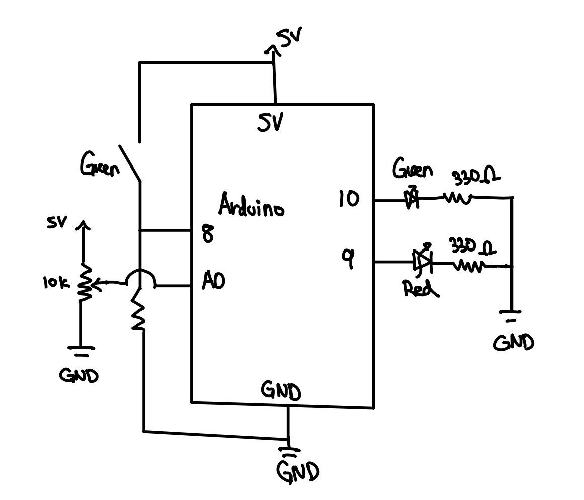
I made a circuit that took in two inputs, green switch and potentiometer. The output is displayed with two led lights: green and red.
int greenPin = 10;
int redPin   = 9;
int buttonPin = 8;
int potPin    = A0;

void setup() {
  pinMode(greenPin, OUTPUT);    //two outputs led
  pinMode(redPin, OUTPUT);
  pinMode(buttonPin, INPUT);   //Input for button

  digitalWrite(greenPin, HIGH);   //testing if leds work
  delay(1000);
  digitalWrite(greenPin, LOW);
  digitalWrite(redPin, HIGH);
  delay(1000);
  digitalWrite(redPin, LOW);
}

void loop() {

  int potValue = analogRead(potPin);               //reading potentialometer value
  int brightness = map(potValue, 0, 1023, 0, 255); //scaling the potentimeter from 0 to 255
  int buttonState = digitalRead(buttonPin);        //when pressed it is set as high

  if (buttonState == HIGH) {      //if button is pressed, turn both lights off
    analogWrite(greenPin, 0);
    analogWrite(redPin, 0);
  } else {                          //if not pressed, light's brightness is controlled by pot.
    analogWrite(greenPin, brightness);
    analogWrite(redPin, brightness);
  }
}
Basically, by default, the two led light’s brightness is controlled by the potentiometer. When I turn the potentiometer to max voltage, the led lights light up with maximum brightness. Otherwise, if I turn the potentiometer to 0, it means that the voltage becomes 0, hence showing no light.
Another input is the green switch and I made it so that when the button stage is high, meaning that when its pressed, the output becomes , turning the lights off.
This is the sample video:
This is the hand-drawn schematic, that we practiced in class today. Re-drawing it definitely helped.