Concept
The musical instrument that inspired us to create our project for the week, is the xylophone. An instrument that is both interesting and easy to navigate, which made for the perfect interactive musical instrument to create using arduino. We created it using three tinfoil strips that each play a different note when they are pressed, with a potentiometer controlling the frequency of every note adding dimension. The ability to control two different elements such as the note played and it’s frequency provides the user of the participant the ability to create a range of sounds, diversifying the possible experiences that one can create with our instrument.
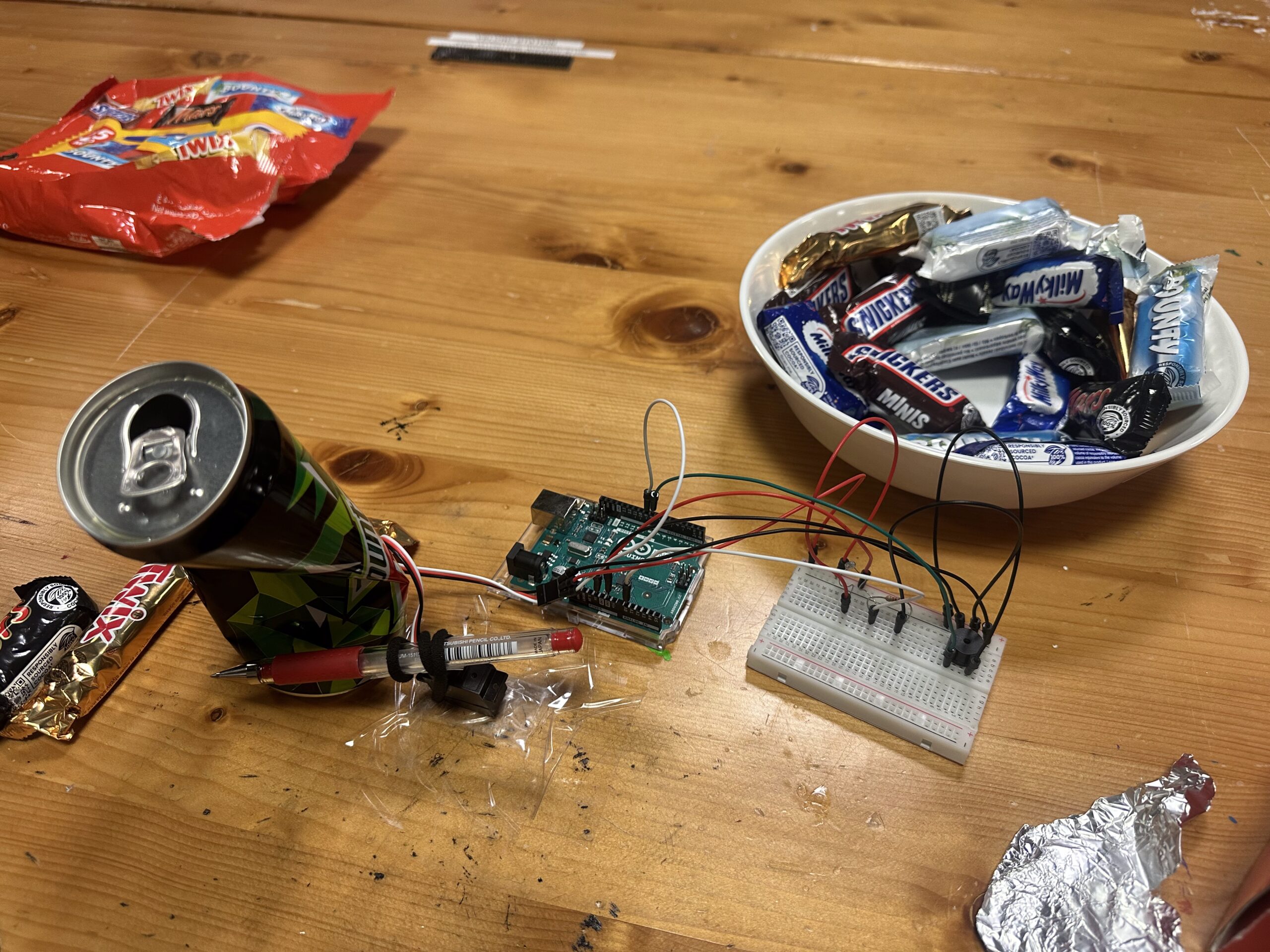
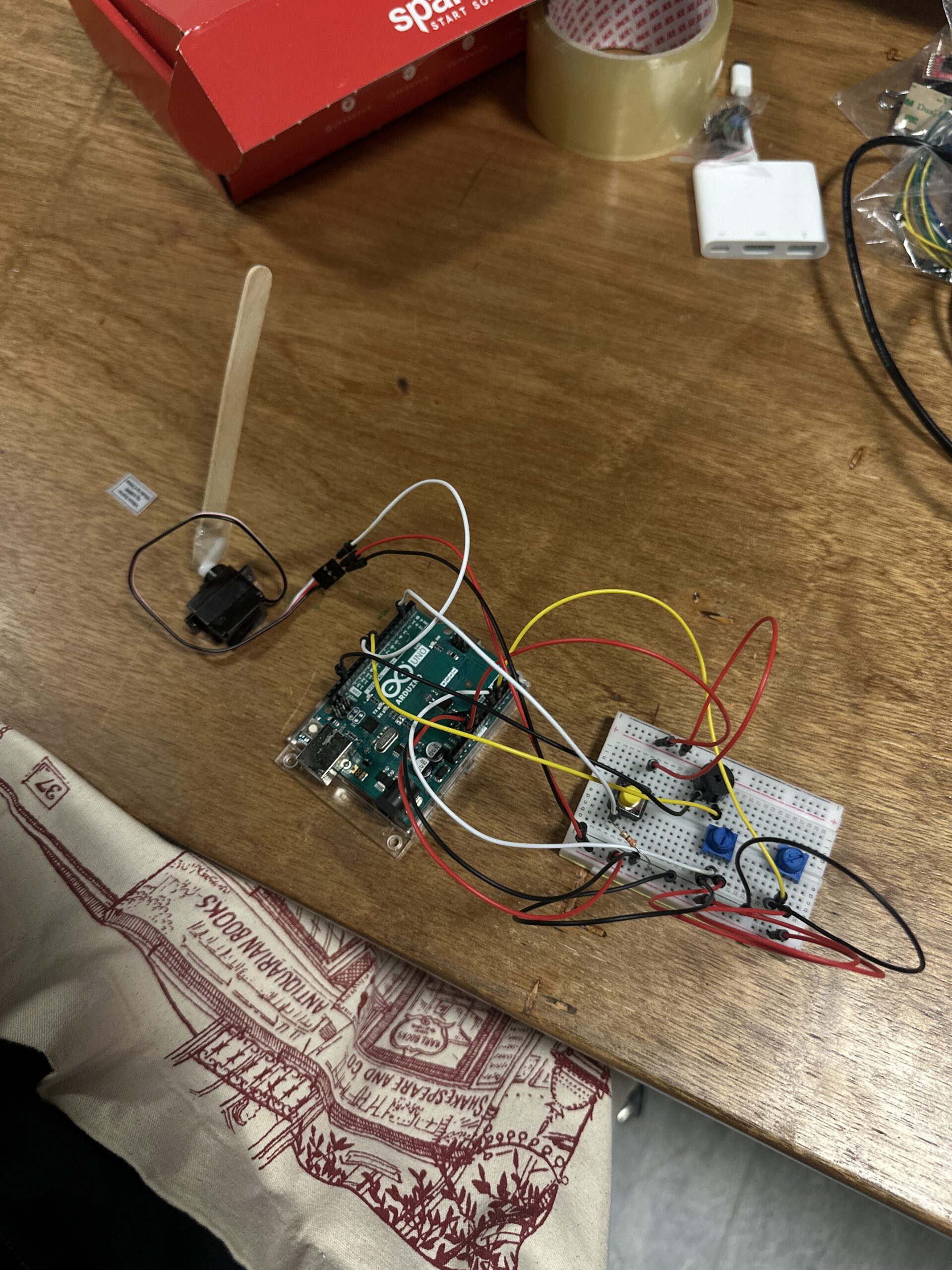
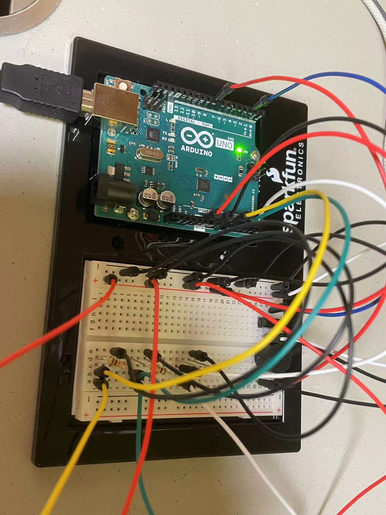
Demonstration
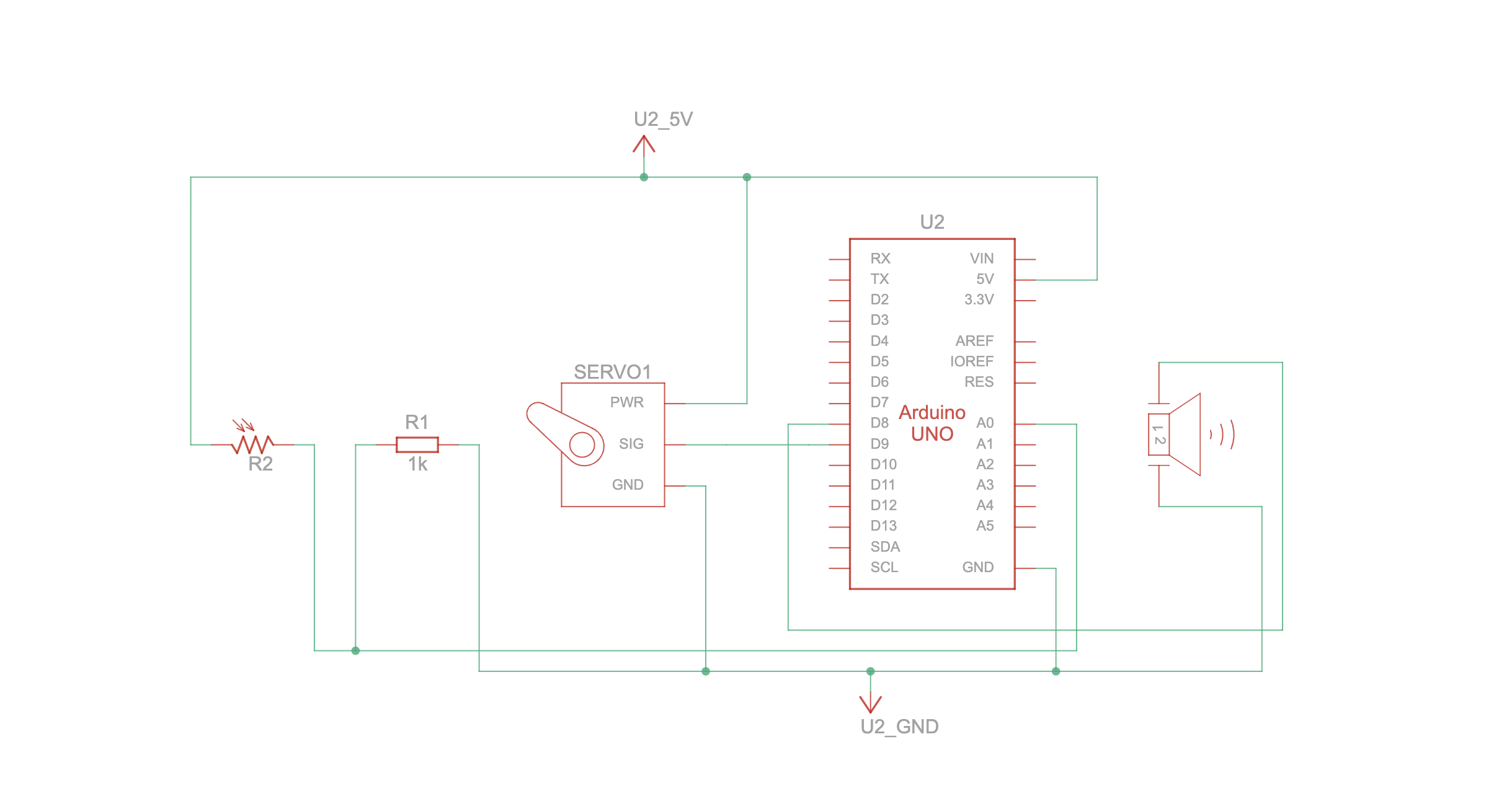
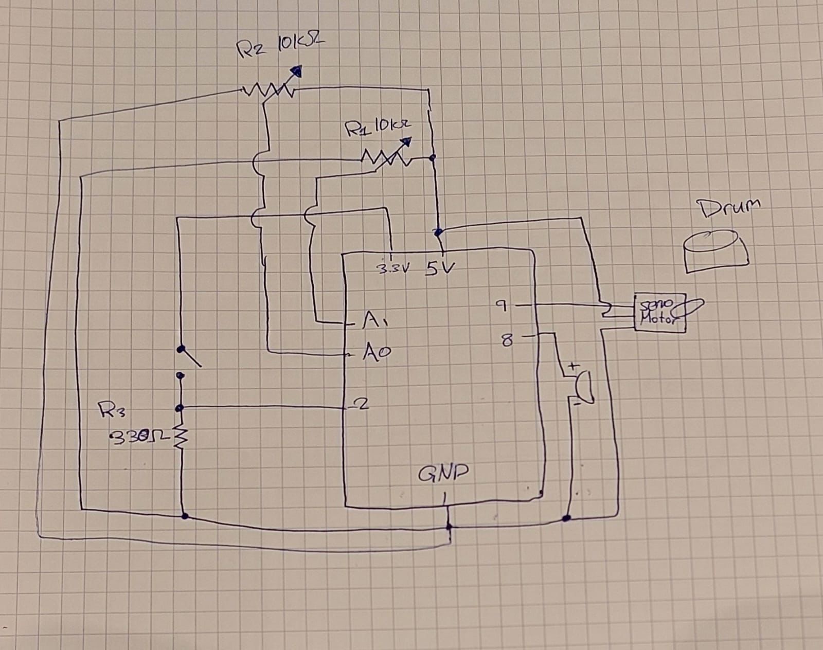
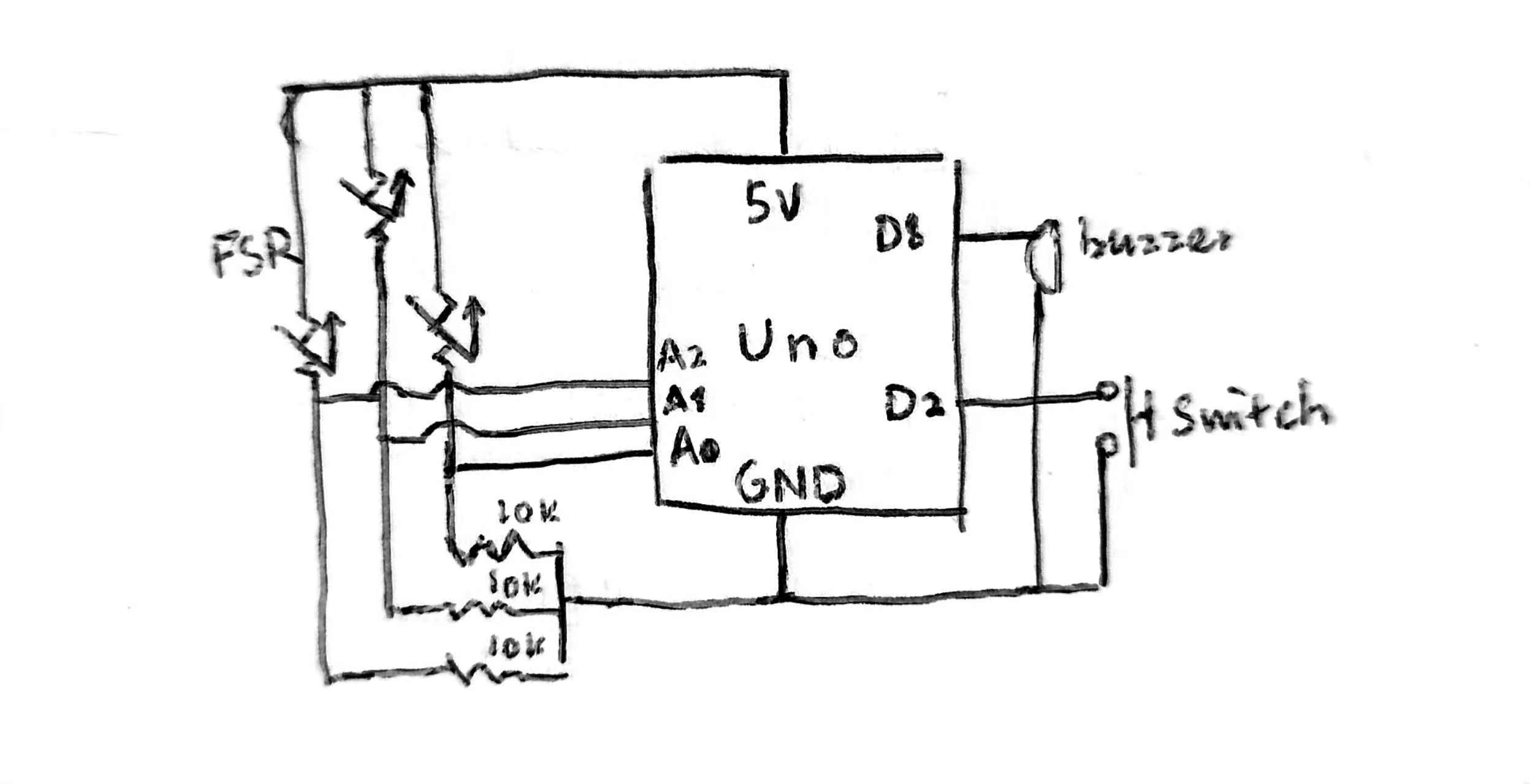
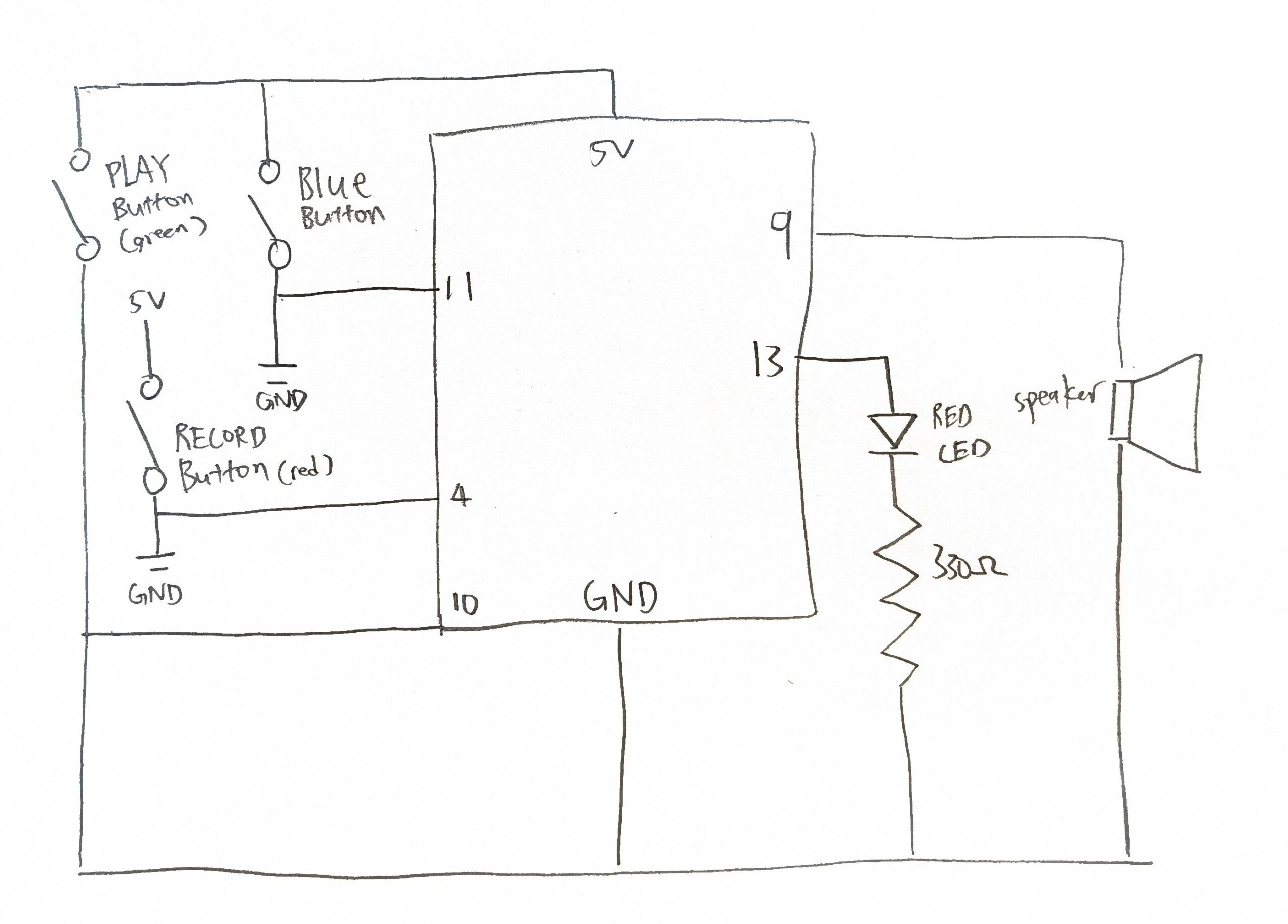
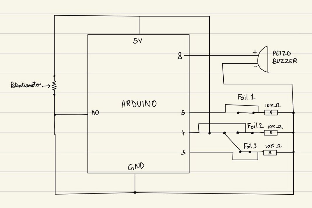
Schematic
Code Snippet
 if (activeIndex >= 0) {
    int freq = int(baseFreqs[activeIndex] * multiplier);
    freq = constrain(freq, 100, 5000);

    tone(buzzerPin, freq);
    Serial.print("Strip "); Serial.print(activeIndex+1);
    Serial.print(" freq=");
    Serial.println(freq);

    delay(50);
  } else {
    noTone(buzzerPin);
}
This part of code was one that was the most challenging, as it controls all important elements of our instrument. I would say it is where all the magic happens, bringing together both the analog and digital input to create the right sound intended by the player of the instrument. It calculates the final tone by multiplying the base frequency by a set multiplier, keeping the result within a safe range, and then sends this signal to the buzzer. When no input is detected, the sound stops. Essentially, it acts as the core logic that translates user interaction into audible output.
Full Code
Reflection
This week’s assignment felt like a more interactive work, building up on our previous projects and adding dimension using more elements. For future improvements we would like to add a limit to the duration a note plays similar to an actual xylophone where a note stops after a certain time after playing a note. This imitates an actual instrument creating a more natural and realistic feel to the work, even playing multiple notes allowing the connection of more than one foil strip and more buzzers. For future projects, I’d like to focus more on aesthetics and adding more visual elements to the works.