Week 9: Sensors

Concept

It was my birthday recently and while thinking of this week’s assignment, I came up with the idea to create a birthday-themed project. I wanted to specifically capture the moment when the lights are turned off and your loved ones bring a cake to you with candles on it while singing happy birthday.

How To Take Birthday Candle Photos

Implementation

Link to demonstration video

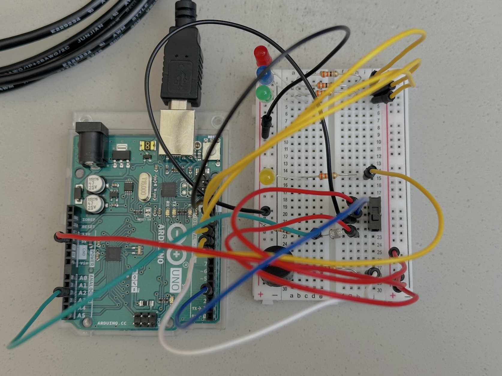
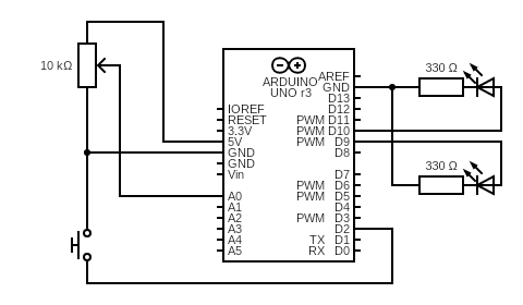
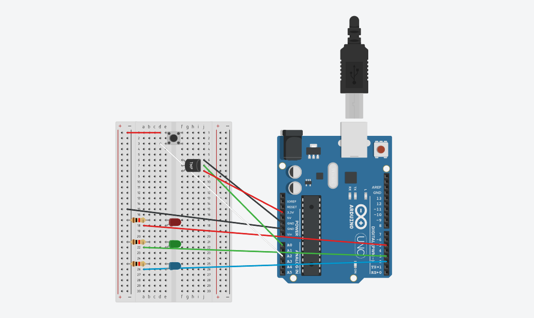
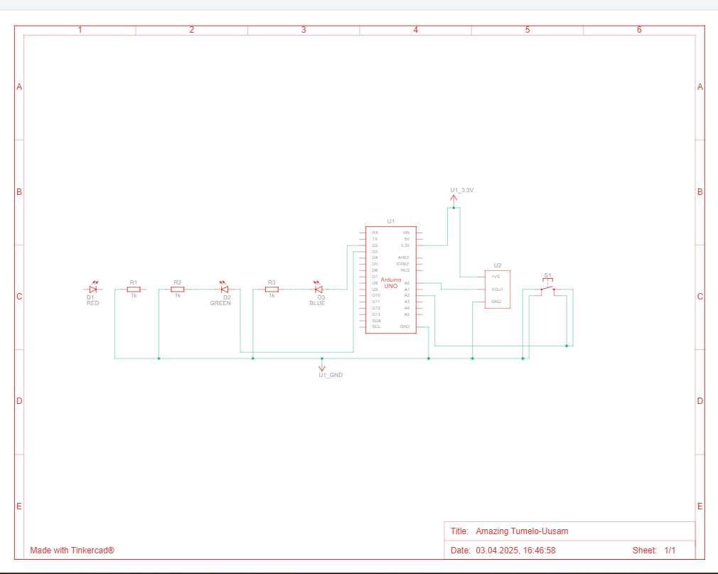
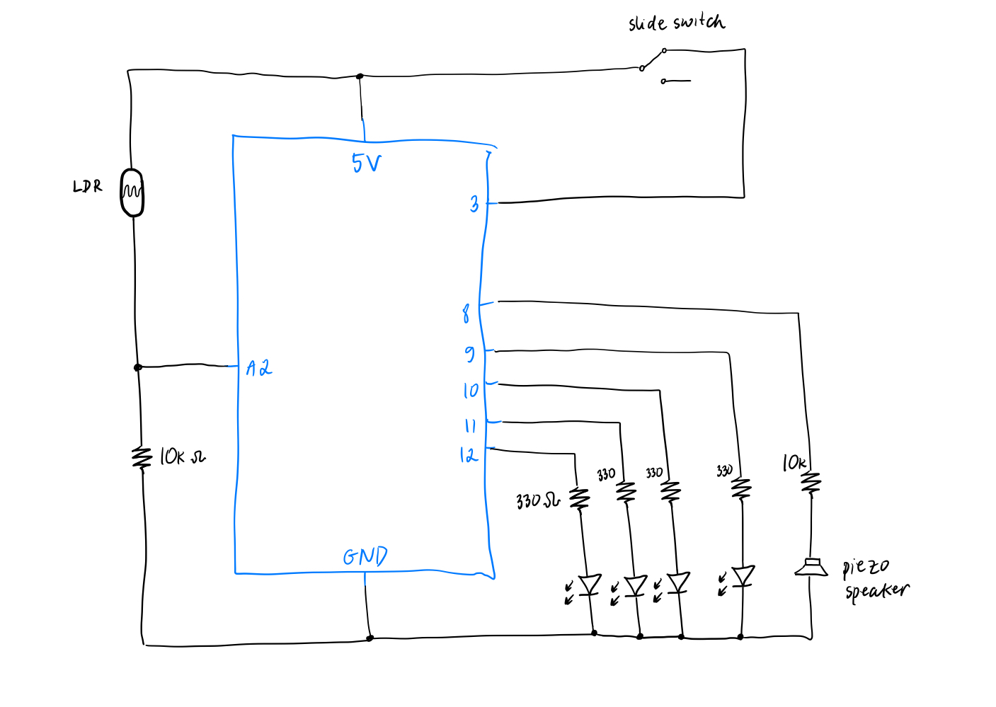
The analog sensor is a photoresistor that controls the on/off state of the 3 LEDs (red, blue and green). When the brightness is below a certain threshold, i.e. the room is dark, the 3 LEDs light up, as if party lights are turned on. The digital sensor (switch) is a slide switch that we perform a digitalRead from. When the switch closes the circuit, the yellow LED in the middle lights up to simulate a birthday candle being lit up and the piezo speaker starts playing the birthday song. The song and the yellow LED can be stopped by sliding the switch to open the circuit.

We didn’t use the slide switch in class and I was a bit confused by the 3 pins, so I referred to this video to complete the analog sensor portion. Another cool resource I found is this GitHub repo that contains Arduino code for a bunch of different songs and melodies. I simply copy pasted the code for the birthday melody from this repo and it worked perfectly!

// ------------ source: https://github.com/robsoncouto/arduino-songs/blob/master/happybirthday/happybirthday.ino
// happy birthday song portion
// change this to make the song slower or faster
int tempo = 140;

// change this to whichever pin you want to use
int buzzer = 8;

// notes of the melody followed by the duration.
// a 4 means a quarter note, 8 an eighteenth , 16 sixteenth, so on
// !!negative numbers are used to represent dotted notes,
// so -4 means a dotted quarter note, that is, a quarter plus an eighteenth!!
int melody[] = {

  // Happy Birthday
  // Score available at https://musescore.com/user/8221/scores/26906

  NOTE_C4,4, NOTE_C4,8, 
  NOTE_D4,-4, NOTE_C4,-4, NOTE_F4,-4,
  NOTE_E4,-2, NOTE_C4,4, NOTE_C4,8, 
  NOTE_D4,-4, NOTE_C4,-4, NOTE_G4,-4,
  NOTE_F4,-2, NOTE_C4,4, NOTE_C4,8,

  NOTE_C5,-4, NOTE_A4,-4, NOTE_F4,-4, 
  NOTE_E4,-4, NOTE_D4,-4, NOTE_AS4,4, NOTE_AS4,8,
  NOTE_A4,-4, NOTE_F4,-4, NOTE_G4,-4,
  NOTE_F4,-2,
 
};

// sizeof gives the number of bytes, each int value is composed of two bytes (16 bits)
// there are two values per note (pitch and duration), so for each note there are four bytes
int notes = sizeof(melody) / sizeof(melody[0]) / 2;

// this calculates the duration of a whole note in ms
int wholenote = (60000 * 4) / tempo;

int divider = 0, noteDuration = 0;
// ------------

int analogPin = A2;
int switchPin = 3;

void setup() {
  Serial.begin(9600);

  pinMode(12, OUTPUT);
  pinMode(11, OUTPUT);
  pinMode(10, OUTPUT);
  pinMode(9, OUTPUT);
  pinMode(switchPin, INPUT);
}

void loop() {

  int lightValue = analogRead(analogPin);
  int switchState = digitalRead(switchPin);
  
  // turn on the red, blue, green LEDs
  if (lightValue < 400) {
    digitalWrite(12, HIGH);
    digitalWrite(11, HIGH);
    digitalWrite(10, HIGH);
  } else {
    // turn off the 3 LEDs
    digitalWrite(12, LOW);
    digitalWrite(11, LOW);
    digitalWrite(10, LOW);
  }

  if (switchState == HIGH) {
    // turn on the yellow LED
    digitalWrite(9, HIGH);
    // play happy birthday
    for (int thisNote = 0; thisNote < notes * 2; thisNote = thisNote + 2) {
      // Check switch state during playback
      if (digitalRead(switchPin) == LOW) {
        digitalWrite(9, LOW);   // Turn off the LED
        noTone(buzzer);         // Stop any sound
        break;                  // Exit the loop
      }

      divider = melody[thisNote + 1];
      if (divider > 0) {
        noteDuration = (wholenote) / divider;
      } else if (divider < 0) {
        noteDuration = (wholenote) / abs(divider);
        noteDuration *= 1.5;
      }

      tone(buzzer, melody[thisNote], noteDuration * 0.9);
      delay(noteDuration);
      noTone(buzzer);
    }
  } else {
    // turn off the yellow LED
    digitalWrite(9, LOW);
    // stop playing happy birthday
    noTone(buzzer);
  }

  Serial.println(lightValue);
}

Challenges and Future Improvements

I really liked working on this week’s assignment and I am quite happy with the concept as well as the final result. I did try to make the candle (aka the yellow LED) blow-able, by taking the wind-blowing idea from Mustafa, so that when you make a blow, the LED turns off, but I got stuck on seamlessly closing/opening the circuit with wind without using a very lightweight/airy material like aluminium foil (as I didn’t have any with me ), so I let go of that idea in the end. All in all, I am happy I got to further review and practice working with Arduino, and now I am feeling a lot more comfortable working with it!

Week 9 – Production

Initial Idea

The goal of this project was to explore the interaction between analog and digital sensors and how they can be used to control outputs creatively. Specifically, the task was to use at least one analog sensor and one digital sensor to control two LEDs, one through digital means (on/off) and the other through analog means (brightness control). The initial idea was to keep the components simple but effective: a push-button as a digital switch and a potentiometer as an analog input, controlling a red and green LED, respectively.

Video demonstration

Execution

The red LED was connected in series with a 330-ohm resistor and controlled by a push-button, which toggled it on or off based on the button state. The green LED was also connected with a 330-ohm resistor and its brightness was adjusted using a 10k potentiometer wired to an analog input pin. The analog value was read from the potentiometer and mapped to a PWM value to vary the green LED’s brightness.

Here is a diagram:


const int potPin = A0;
const int buttonPin = 2;
const int ledDigital = 10;
const int ledAnalog = 9;

bool ledState = false;

void setup() {
  pinMode(buttonPin, INPUT_PULLUP); // button active LOW
  pinMode(ledDigital, OUTPUT);
  pinMode(ledAnalog, OUTPUT);
}

void loop() {
  // Read potentiometer value
  int potValue = analogRead(potPin); // 0 - 1023

  // Map it to PWM range
  int brightness = map(potValue, 0, 1023, 0, 255);
  analogWrite(ledAnalog, brightness);

  // Read button
  if (digitalRead(buttonPin) == LOW) {
    delay(200); // debounce
    ledState = !ledState;
    digitalWrite(ledDigital, ledState);
  }

  delay(50); // loop delay
}


Highlights 

  • The logic worked exactly as planned: the button cleanly toggled the red LED, and the potentiometer provided smooth brightness control for the green LED.

  • The circuit was clean, and the schematic clearly represents the wiring and design intent.

  • I’m proud of how the components were chosen and integrated in a way that’s both simple and pedagogically effective, perfect for demonstrating basic input/output handling on Arduino.

What Could Be Improved

  • Debouncing the push-button in code could be refined further to prevent unintended toggles.

  • A creative twist (e.g., combining analog and digital inputs for more complex LED behaviors or using a different type of analog sensor like an LDR) could elevate the interactivity.

  • Next time, I might also add a small OLED screen or serial output for live feedback on sensor values for better debugging and visualization.

Week 9 Reading Response

Reading Tom Igoe’s “Physical Computing’s Greatest Hits (and Misses)” honestly made me feel a lot more relaxed about project ideas. At first, it seemed like a list of all the things people have already done too many times, like gloves that make music, video mirrors, or floors that light up when you step on them. But then Igoe flips that idea. He basically says it’s okay to revisit these themes because what makes them interesting isn’t the concept itself, but how you approach it. That felt very refreshing. It reminded me that originality doesn’t mean starting from nothing every time. It can come from how you add your own twist to something familiar.

What I also appreciated was how much these themes connect to actions we already do in real life, like tapping, dancing, waving, tilting, or even yelling. It’s amazing how intuitive some of these interactions are, and how physical computing works with that. You don’t have to explain much when someone naturally knows how to interact with your piece.

In “Making Interactive Art: Set the Stage, Then Shut Up and Listen”, Igoe talks more about the role of the artist or designer in this kind of work. The main idea that stood out to me was that we shouldn’t try to control how people respond or tell them exactly what to think. Interactive work is more like setting up a space or a situation and then letting people figure it out on their own. I liked the comparison to a theater director. You can give actors tools and a setting, but the emotional part of the performance has to come from them. The same thing goes for interactive art. It only works when people bring something of themselves to it.

Both readings helped shift the way I think about making interactive projects. It’s not just about cool tech or trying to be the most unique. It’s really about creating something that invites people to participate and explore. Ideally, they leave with their own story or feeling from it, not just the one I imagined in advance.

Reading Reflection: Week 9

Physical Computing’s Greatest Hits (and misses)

One idea that really resonated with me is the reminder not to give up on a project just because it’s been done before. I’ve done it myself in the past when i would get excited about an idea for an IM project, only to do my research and see that someone else had already made something similar. That would make me feel like it wasn’t “original enough,” so I’d opt out to do something different.

The reading made me realize that two people can execute the exact same concept in totally different ways. The author mentions how even common topics in physical computing can still offer surprises through personal variation. I especially liked the example of using your body or hand as a cursor as no two drawings will ever be the same, and that kind of interactivity can’t be duplicated.

I also really agree with his implication that what’s important is not what the computer can do, but what the person can do. It is more about how people respond, interact, and express themselves through interacting with technology.

Making Interactive Art: Set the Stage, Then Shut Up and Listen

The main idea that the artist shouldn’t interpret their own work reminded me of how some painters intentionally choose not to add descriptions to their works – they leave it up to the viewer to decide on their own meaning. In terms of Interactive Media, this made me think about how the project has to be self-explanatory, as all elements should guide the user without any extra instructions.

Another idea that creators should listen to how people respond to their work is something I don’t think I’ve ever done intentionally. I’ve tested projects to see if they work, but I haven’t truly observed how people feel or what unexpected things they do with it. It also reminded me of another reading we had earlier about interaction being a conversation, not just a monologue from the author. I think I would like to try building projects that leave room for interpretation and do unexpected things.

Week 9: Sensor Assignment

My Concept

The project is a thermometer system that uses an analog temperature sensor and a button switch to control three LEDs: blue for cold (22°C and below), green for moderate temperatures (24°C to 27°C), and red for warmer temperatures (27°C and above).

The button works as a power switch, making the LED that matches the current temperature light up. At first, I wanted all the LEDs to turn on when the button was pressed and then, after touching the temperature sensor, have only the LED for the detected temperature stay on. But that didn’t work out, so I adjusted the setup to make the button directly activate the correct LED based on the sensor’s reading.

Set-up


Code

Github Code

Highlight:

As the temperature sensor doesn’t directly give the temperature, I had to convert the initial number (an ADC reading) into volts, then into millivolts  and then use a formula to calculate the temperature in Celsius. After that, I converted it into Fahrenheit

reading = analogRead(sensorPin);  
volts = reading * aref_voltage / 1023.0;
millivolts = 1000 * volts;
degreesC = (millivolts - 500) / 10;
degreesF = (degreesC * 9 / 5) + 32;

Reflections

This project taught me how important it is sometimes to start completely from scratch. In my first attempts, the TMP sensor got overheated, which was most likely because I positioned some components in a way that caused issues in the circuit. I ended up having to rebuild everything a few times. It was frustrating at first, but ultimately a great learning experience. To refine my future projects, i’d love to experiment with more sensors in our kit and see how it goes. Overall, i enjoyed the creation of this project.