Description:
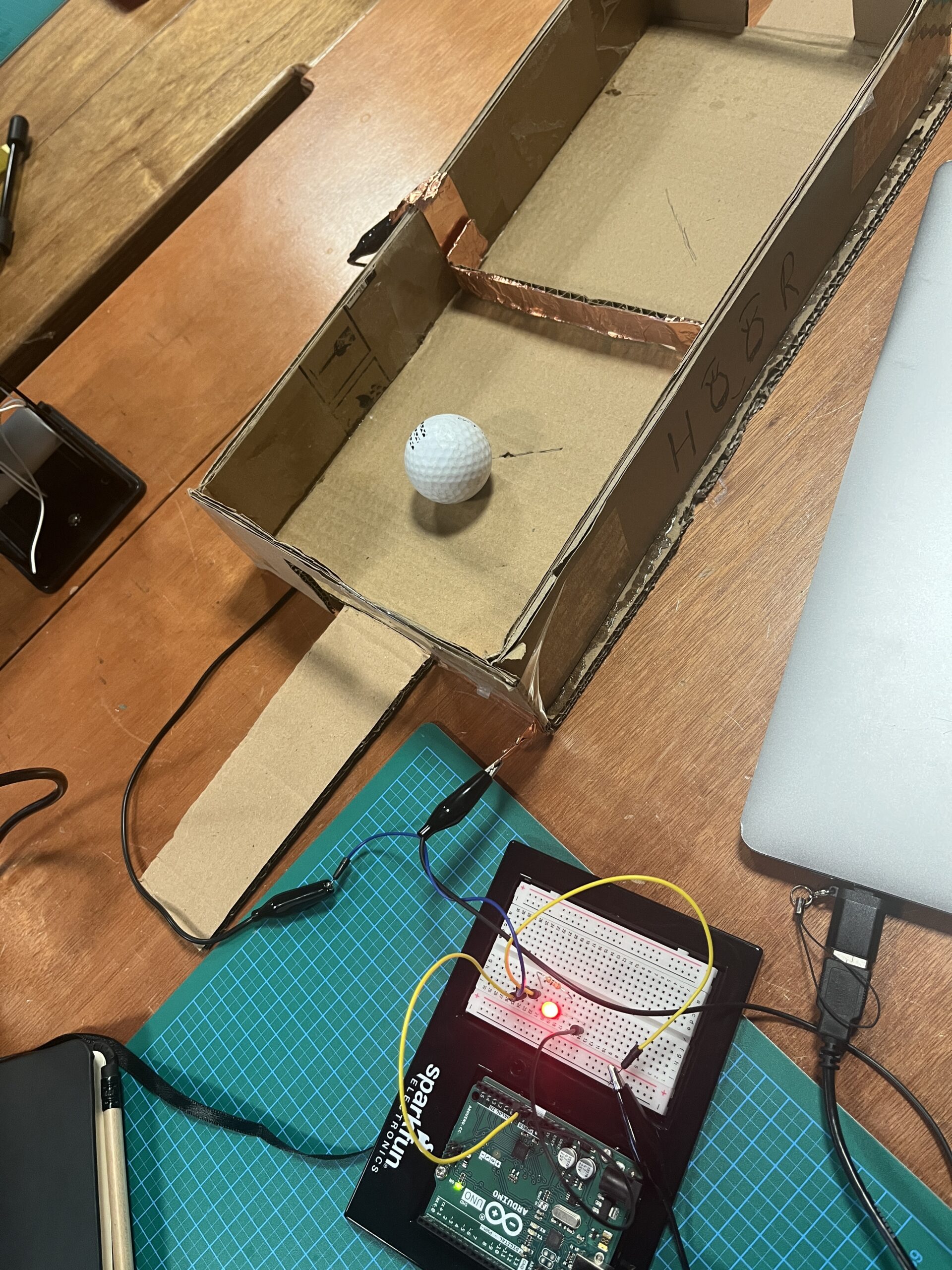
I really wanted to try using the ultrasonic motion sensor for this week’s assignment and control both audio and visuals with it. Being able to have your hand control something without touching it seemed cool to me, kind of like the theremin instrument that allows musicians to wave their hand in the air to produce different notes. My assignment is much simpler, but has a similar idea in that the closer your hand gets to the sensor, the lower the pitch. I also have LEDs hooked up that get dimmer the closer your hand gets and brighter the farther away. For the digital sensor, I have a button controlling my 4 LEDs; the button allows you to toggle between the LEDs individually. Once you’ve gone through all the LEDs and press the button again, all of them turn on.
Video demonstration:
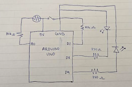
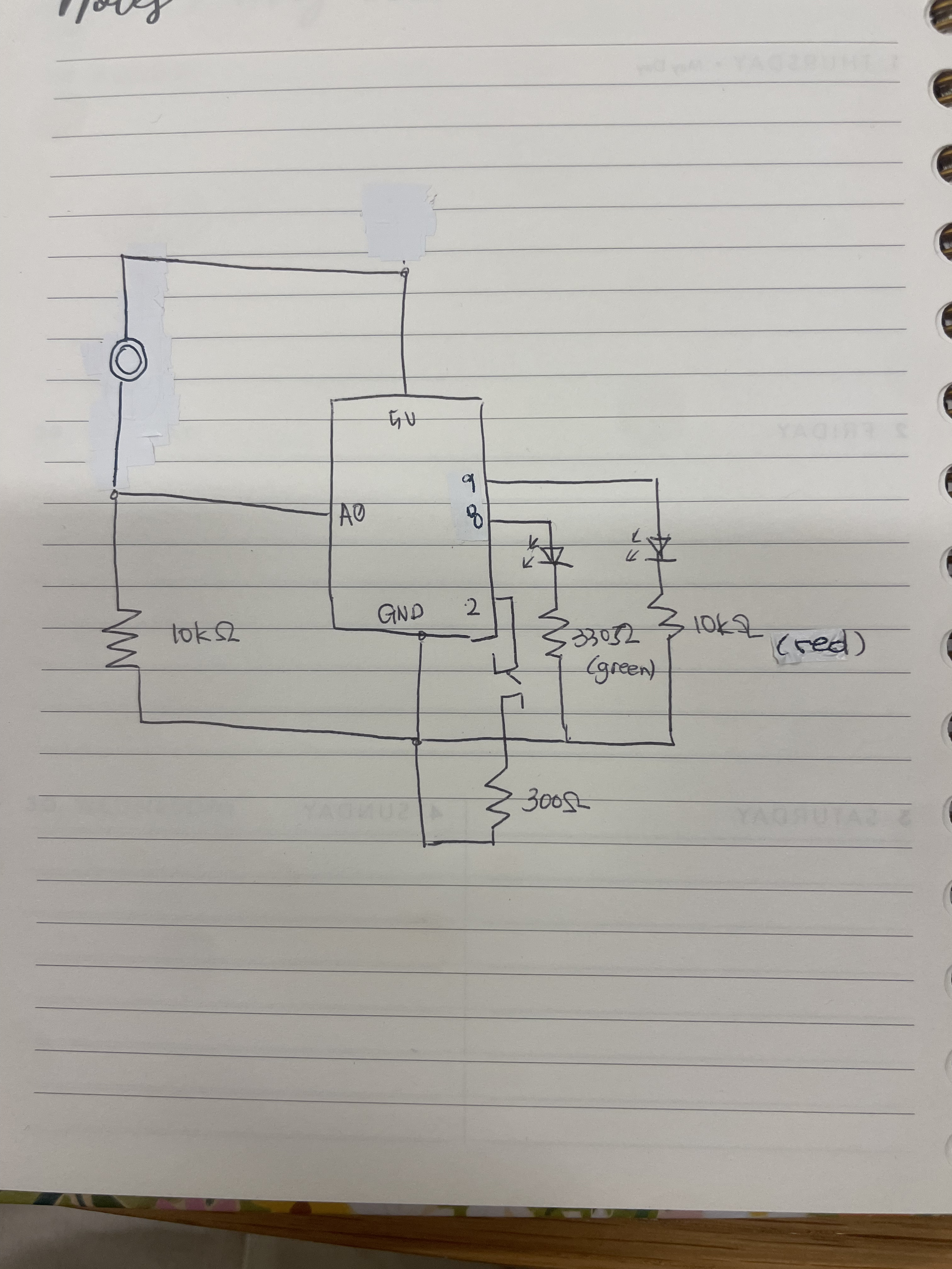
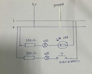
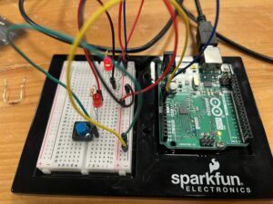
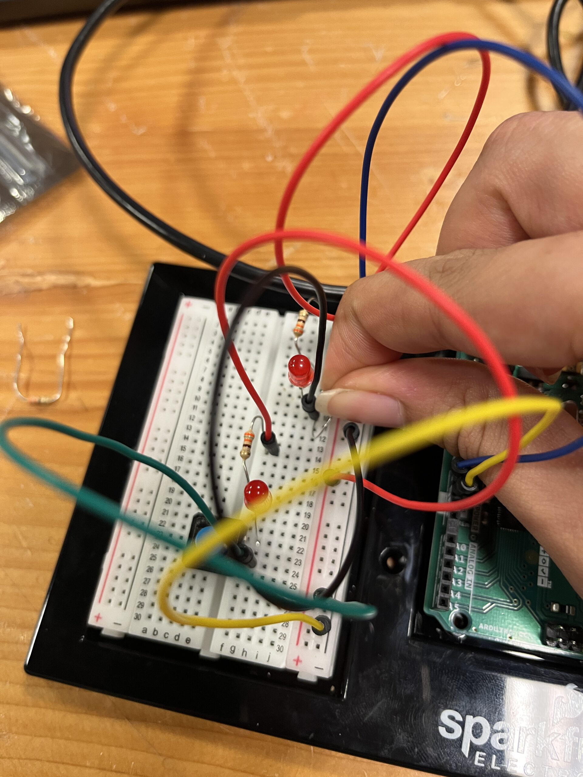
Schematic: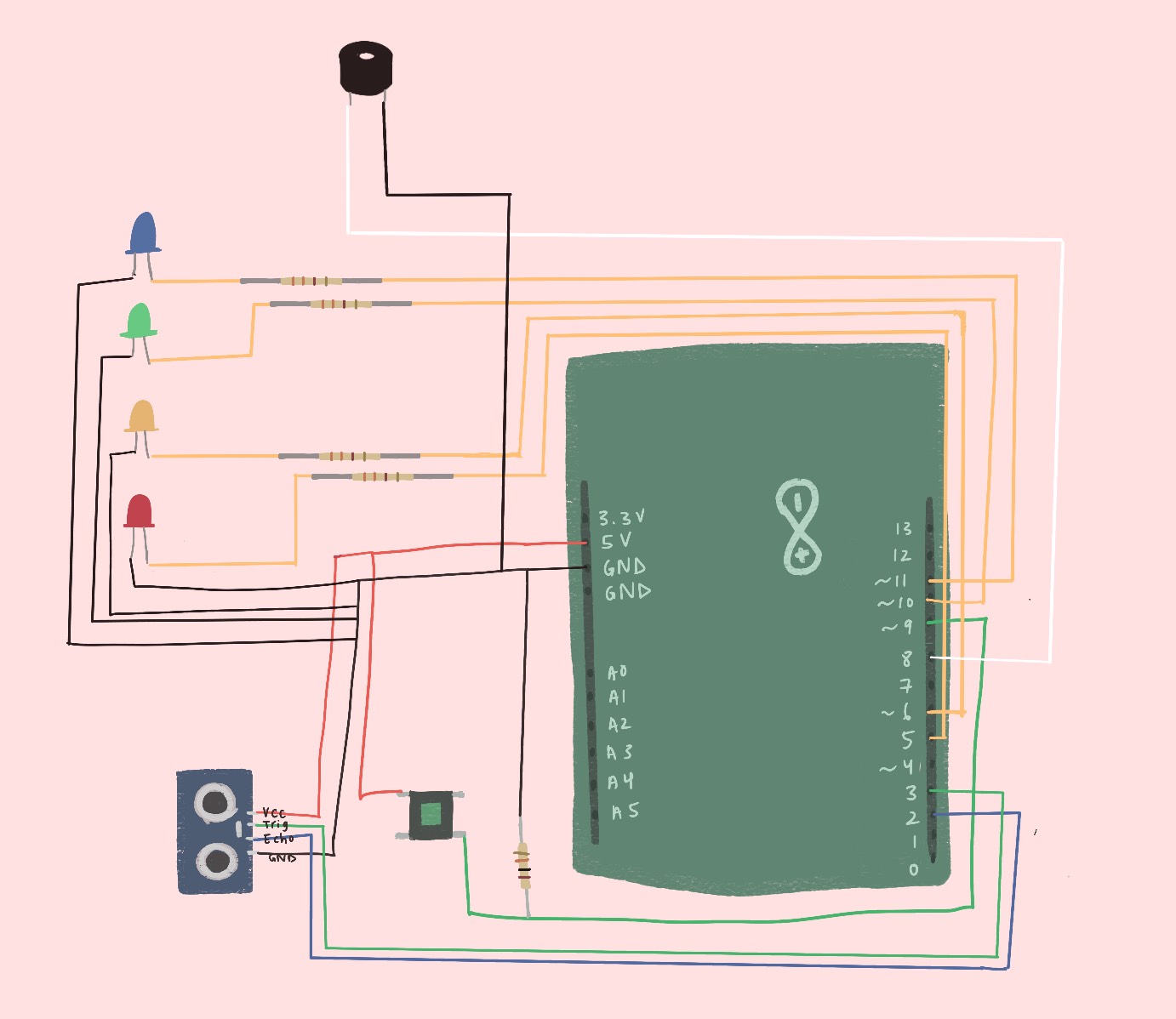
Difficulties:
I had a hard time with the button because it wasn’t as simple as pressing it to toggle between the LEDs. When you press the button, you’re technically holding it and giving it HIGH voltage for multiple frames. That means within one button press, I’m toggling between who knows how many LEDs. However, I only want one button press to change one thing. I did some scouring online and found this state-changing example that made me realize I can just detect when the button goes from LOW to HIGH (off to on). By keeping track of the last button state and current button state, I can detect when the user clicks the button. That instance determines whether or not to toggle between the LEDs: https://docs.arduino.cc/built-in-examples/digital/StateChangeDetection/
Button state change:
// compare current and previous button states, see if there's change
if (buttonState != lastButtonState) {
   // if HIGH, button went from off to on
   if (buttonState == HIGH) {
Mapping distance to LED brightness:
analogWrite(LEDarr[currentLED], map(dist, 0, 20, 0, 255));
if (dist < 3) {
  analogWrite(LEDarr[currentLED], 0);
}
It was also difficult making the different pitches noticeable since the motion sensing isn’t the most accurate and there’s not a huge range to work with. To counteract this, I chose notes that were very far apart from each other to make the change in sound due to distance more apparent. I also made sure to print out the distances to how far a person would comfortably go away from the sensor and used that as my max.
Looking forward:
In the future, it would be nice if maybe I map a specific LED/color to a specific note or melody so that when I play songs from the speaker, the lights match accordingly. It would also be cool if I can play a song from the motion sensor and choose what notes to play given the distance/motion.