For this project, we were asked to use both a digital and an analog sensor to control two separate light bulbs. I chose an LDR as the analog sensor and a push button switchas the digital one.
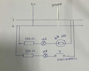
The circuit was designed with both connections set up in parallel, but each individual sensor and its LED were wired in series. That means the LDR is connected to a resistor and then to an LED in one path, while the button switch is connected to a resistor and another LED in a separate path. Both paths share power and ground—so they’re technically in parallel, but operate independently.
My favorite part of the project was seeing how the LDR affected the brightness of the LED in real-time. The more light it receives, the dimmer the LED gets, and vice versa. It was satisfying to see that dynamic shift as I covered and uncovered the sensor.
For the digital sensor, the behavior is much simpler: the LED turns on when the button is pressed and turns off when it’s released. There’s no change in brightness—just a clean on/off action.
One challenge I faced was protecting the LEDs from burning out. I ended up frying three of them before realizing that I needed to be more careful with resistor values and connections. In the end I started disconnecting my board from power before making any changes to the connections which I realize now I should’ve done from the start but I just forgot about it.
For future improvements, I’d love to swap the LDR for a microphone sensor and make the LED respondto sound intensity instead of light. I thinkit would be fun to experiment with how volume or rhythm could control brightness, especially for interactive or musical projects.
Hand-drawn schematic diagram:
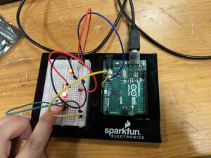
Switch not pushed. LDR exposed to room light.
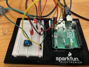
Switch not pushed. LDR covered.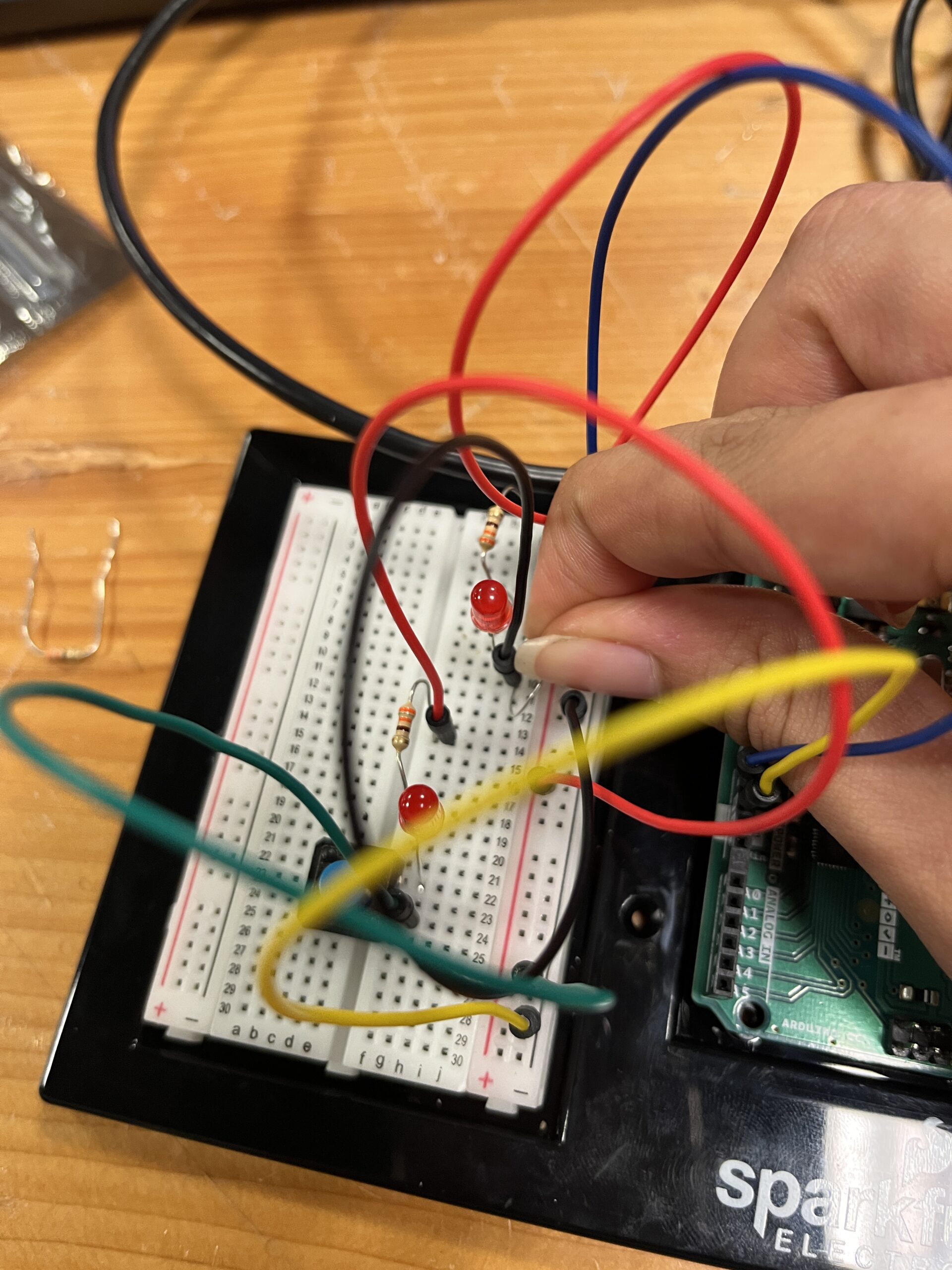
Switch pushed. LDR exposed to room light.