
For this week’s assignment, we are asked to use at least one analog input to control one LED and at least one digital input to control one LED. I haven’t added the sketch yet so I am going to come back and add that creative element later!
I had fun with the line graph displaying the knobValue before and after being mapped. I made the graph curve by rotating the potentiometer. Below are the graph and the video of that:
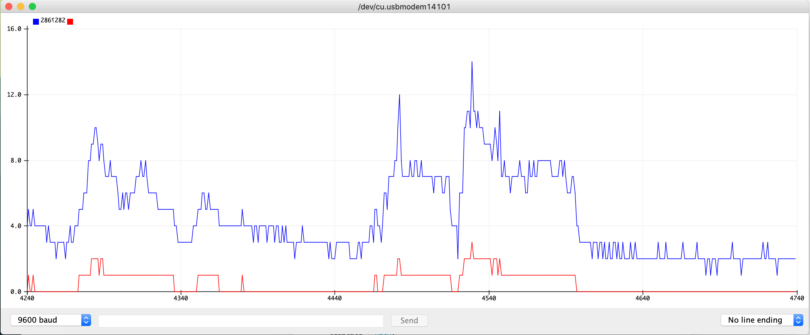
Testing the button (digital input) and the potentiometer (analog input):
This is the code (how to make it color-coded though?) (updated: oh! it is color-coded in the post but not right in the editing space)
const int ledPinYellow = 3;
const int ledPinGreen = 7;
const int ledPinBlue = 12;
const int buttonPin = 2;
int knobPin = A0;
int ledState = LOW;
int prevButtonState = LOW;

void setup() {
  pinMode(ledPinYellow, OUTPUT);
  pinMode(ledPinGreen, OUTPUT);
  pinMode(ledPinBlue, OUTPUT);
  pinMode(buttonPin, INPUT);
  //pinMode(A0, INPUT);

  Serial.begin(9600);
}

void loop() {
  int knobValue = analogRead(knobPin);
  int mappedValue = map(knobValue, 0, 1023, 0, 255);
  Serial.print(knobValue);
  Serial.print("    ");
  Serial.println(mappedValue);

  analogWrite(ledPinYellow, mappedValue);


  int currentButtonState = digitalRead(buttonPin);

  if (currentButtonState == HIGH && prevButtonState == LOW) {
      // flip the LED state
      if (ledState == HIGH){
        ledState = LOW;
      } else if (ledState == LOW){
        ledState = HIGH;
      }
  }
  // if you want to print out the LED state
  // Serial.print(ledState);

  digitalWrite(ledPinGreen, ledState);
  digitalWrite(ledPinBlue, !ledState);

  //we need to remember the state of our button for the next time through LOOP
  prevButtonState = currentButtonState;
}