All Posts

Arduino: analog input & output

This week I used both an analog and a digital sensor to control two LEDs in different ways. I used the ultrasonic distance sensor to measure distance. For the digital sensor. My setup controls two LEDs: one blinks and the other changes brightness using PWM.

Here’s how it works:
LED1, connected to a regular digital pin, blinks faster when an object is closer and slower when it’s farther away. The delay between blinks is based on the distance in centimeters. So the closer the object, the faster the LED blinks. If the object is far, the LED blinks slowly.

LED2, connected to a PWM pin, changes brightness based on the same distance. But instead of getting dimmer when the object is far (which is more common), I made it do the opposite—it’s dim when the object is close and bright when it’s far away. I know it’s the reverse of what people usually do, but I wanted to try something different and see how it looked in action.

the code :

// Pin definitions
const int trigPin = 7;     // HC-SR04 trigger pin
const int echoPin = 6;     // HC-SR04 echo pin
const int led1Pin = 2;     // LED1 pin (digital)
const int led2Pin = 3;     // LED2 pin (PWM)

// Variables
const int maxDistance = 255;  // Maximum meaningful distance (cm)
int distance = 0;             // Measured distance in centimeters
int brightness = 0;           // Variable for brightness

void setup() {
  Serial.begin(9600);
  pinMode(led1Pin, OUTPUT);
  pinMode(led2Pin, OUTPUT);
  pinMode(trigPin, OUTPUT);
  pinMode(echoPin, INPUT);
}

long getUltrasonicDistance() {
  digitalWrite(trigPin, LOW);
  delayMicroseconds(2);
  digitalWrite(trigPin, HIGH);
  delayMicroseconds(10);
  digitalWrite(trigPin, LOW);
  return pulseIn(echoPin, HIGH);
}

void loop() {
  // Measure distance
  distance = 0.01723 * getUltrasonicDistance();
  
  // Cap the distance reading
  if(distance > maxDistance) distance = maxDistance;
  if(distance < 2) distance = 2;  // HC-SR04 minimum range
  
  // Serial output
  Serial.print(distance);
  Serial.println(" cm");
  
  // LED1: Blink with distance-dependent delay (capped)
  digitalWrite(led1Pin, HIGH);
  delay(distance);
  digitalWrite(led1Pin, LOW);
  delay(distance);
  
  // LED2: Brighter when closer, dimmer when farther
  //brightness = map(distance, 2, maxDistance, 255, 0); // Inverted mapping
  //brightness = constrain(brightness, 0, 255); // Ensure valid PWM
  //Serial.println(brightness);
  brightness = distance;
  analogWrite(led2Pin, brightness);

video:

https://drive.google.com/drive/u/0/folders/1Kk2lkQgoAyybXSYWVmY2Dog9uQVX_DMq

future improvement:

In the future, I’d like to add sound that reacts to distance, like pitch changes as you move closer or farther. I also want to make the project more interactive overall—maybe by adding more sensors or letting users trigger different responses through movement or touch. This would make the experience feel more playful and alive.
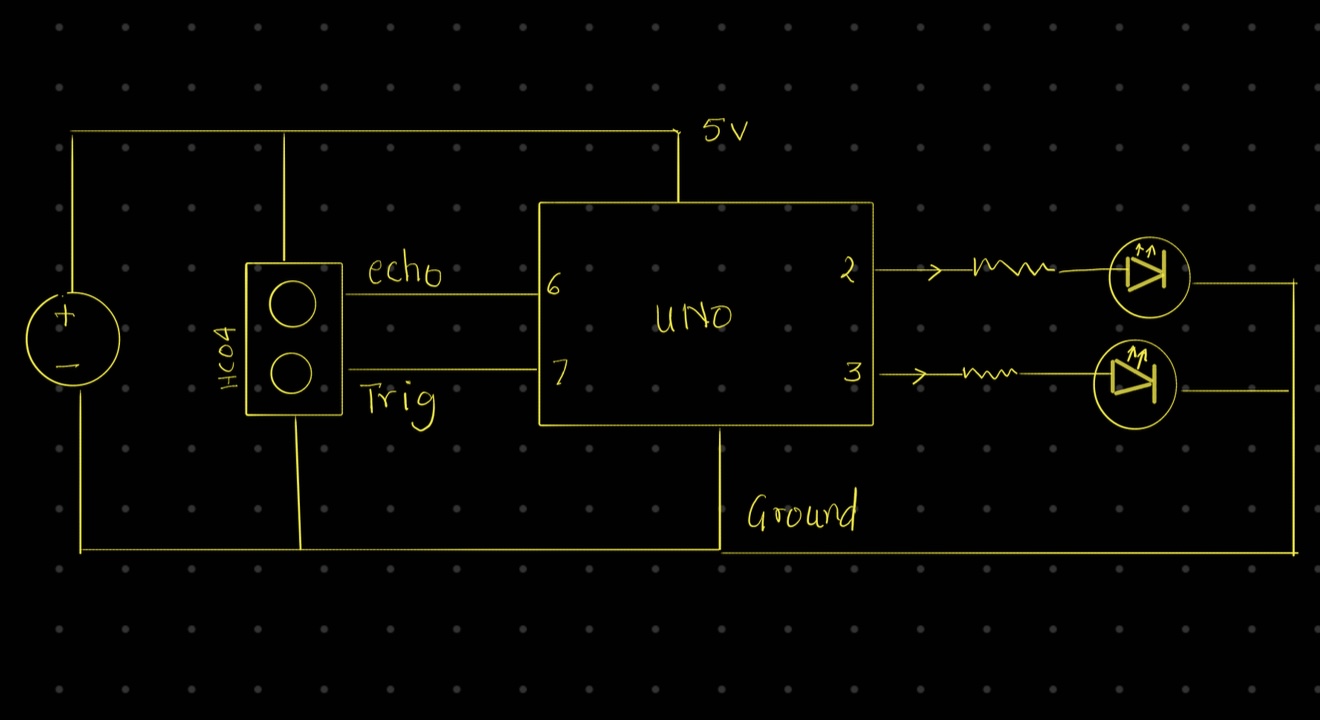
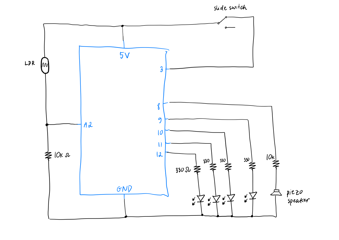
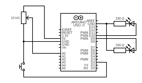
schematic:

Week- 9 reading

This week’s readings made me think about how important it is to be okay with things not always working out. In Physical Computing’s Greatest Hits and Misses, I liked how it showed both the successful projects and the ones that didn’t go as planned. That felt real. I often feel like everything I make has to be perfect, but this reminded me that trying new things and failing is part of the process. It also made me wonder—what really makes something a “failure”? If people still interact with it or feel something from it, maybe it still has value. I want to be more open to things going wrong, because those moments can lead to better ideas.

The second reading, Making Interactive Art: Set the Stage, Then Shut Up and Listen, really stayed with me. I’m used to explaining my work a lot or trying to get people to understand exactly what I meant. But this reading made me realize that sometimes the best thing I can do is let go and let the audience explore for themselves. I don’t fully agree with the idea that artists should just “shut up,” because I think some guidance can help people connect. Still, I like the idea of trusting people more. It made me think about how I can make work that gives people space to feel, move, and react in their own way, without me controlling every part of the experience.

Week 9 – Sensors

Concept: 

When thinking about an idea for this project, I kept coming back to the lights in my room and how they always stayed the same, no matter what the light outside was like, they were either always to bright or too dim. That simple thought inspired me to create a system where they could adjust automatically, so if it’s bright during the day, the lights would stay dim or even stay off, but as the sun sets and it gets darker, they would gradually get brighter and adjust to the environment. 

Implementation/ Setup: 

To implement this, I used the LDR and a button. The button would serve as a simple on/off switch for the LEDs, which would allow me to activate or deactivate the system manually. Then, once the LEDs are turned on, the LDR would take over by detecting the light levels in the room. This means as it gets darker outside, the LDR would read lower light values, which causes the LEDs to become brighter. On the other hand, if it’s bright out, the LEDs automatically dim or even turn off, since additional lighting isn’t really needed. Below is the set up and demo: 

Code/Challenges: 

One of the initial challenges I faced was figuring out how to use both the button and the LDR together in a way that made sense. I wanted the button to first be used to switch the system on, and then only after that should the LDR take over and adjust the LED brightness based on the surrounding light levels. To solve this, I used a boolean variable ledOn, which was inititally set as false, that toggles the LED system on or off when the button is pressed . Once the system is turned on (ledOn true), the LDR starts reading the  light and adjusts the LED brightness accordingly, so darker surroundings make the LEDs brighter, and brighter conditions dim the LEDs. This setup ensured that the button controlled the system’s activation, while the LDR only adjusted the lighting when the system was switched on.

// Detect button press (transition from LOW to HIGH)
 if (buttonState == HIGH && lastButtonState == LOW) {
   delay(50);  // Debounce
   ledOn = !ledOn;  // flips value of ledOn, toggles between on/off
 }


 lastButtonState = buttonState;  // Save current state for next loop


 if (ledOn) {
   // Read light level and map it to brightness
   int lightLevel = analogRead(ldrPin);  // 0 (dark) to 1023 (bright)
   int brightness = map(lightLevel, 0, 1023, 255, 0);  // Invert to make LED brighter in dark


   analogWrite(ledPin1, brightness);
   analogWrite(ledPin2, brightness);
 } else {
   // Turn LEDs off
   digitalWrite(ledPin1, LOW);
   digitalWrite(ledPin2, LOW);
 }
}

Reflection/Improvements: 

Reflecting on this project, one key area for improvement would be expanding the functionality of the button to maybe control more features. So, currently, the button toggles the LED system on or off, but I think it could also be used to switch between different modes or lighting patterns for more dynamic control. For example, I could program the button to cycle through several lighting modes. The first press could turn the system on with brightness adjusted by the LDR as it currently works. A second press could set the LEDs to a fixed brightness level, independent of the light conditions outside, giving the user more control over the lighting. A third press could switch the LEDs to a blinking pattern.

Week 9 Reading

One of the most interseting concepts found in “Physical Computing’s Greatest Hits” I found was the tilty tables. While the concept of tilting and how it can alter the objects on a surface is so very intuitive to us, the tilting table adds a degree of complexity compared to something live a wave wall. The tilting allows for another, interesting way for audiences to interact with art in a non-conventional way that is still very rooted in modern day physics.

One of the most out there ideas was also the meditation helpers; devices designed to take away stimulus. This also struck me as very counter-intuitive yet fascinating. Normally, we think about taking away stimulus when it comes to being in a state to meditate, yet this machine attempts to connect the user to the compuation through the interpretation of a series of sensors in a way I think fuses technology and biopsyhcology in a fascinating way.


From the other article, I found the message to be very important and true. Similar to how Norman said doors that need signs are poorly designed, I think an artwork being able to stand alone with less surrounding context is in some shape or form a testament to its thoughtful design. Because the truth is, if one designs their artwork well enough, operation should be intuitive to the user.

The way the article says to indicate what the user should do with the art is so obvious, but when we ourselves are creating art, from an opposing perspective, it is definitely true that these things are just not as obvious as they would if we were not the artist.

Another important note from the article is to listen for feedback. Unlike other mediums, this one is more able to changed over time with feedback. So when for users there is a disconnect in what needs to be done and what they are trying to do, the artist should really take that into account to improve their work.

Week 9: Analog Inputs and Outputs

Concept

My piece this week was inspired by the recent Eid break we enjoyed. During the break, a couple of friends and I made the 5.5 hour road trip to Muscat, Oman, where we enjoyed a relaxing stay over a couple of nights. On the road trip itself, I took turns driving with a friend, who was a bit newer to driving than I was.

Navigating in the passenger seat really revealed the complexity of driving that had become a form of second-nature to me, after driving to high school almost every day since I turned 16 back in the US. Certain movements were inherently complex requiring a combination of precise motor muscle movements to be coordinated at the same time. For instance, turning in a roundabout is a hodgepodge of visual queues from oncoming traffic, a crescendoing breaking, mirror checks, precise wheel adjustments, and juggling the break and gas pedals with your feet. Once you’ve driven for a while, you begin to take for granted the muscle-memory you built up over years of experience.

This piece of art is a small encapsulation of some of those mechanisms–while reversing some of the expectations you may traditionally think of for automobiles. For instance, rather than turning a steering wheel, you turn the wheel wheel, powering on gas light. The potentiometer adjusts your servo motor (along with a blue light), which mimics the car’s wheel turns. Lastly, in case of emergency, you can always press the red button to sound the alarms and hopefully bail yourself out of trouble–honking the buzzer horn.

Reading Reflection – Week 9

Physical Computing’s Greatest hits and misses

The blog post compiles and reviews popular themes in physical computing. As we head into the last few weeks of the semester and as I start thinking about the final project, I found myself having a hard time coming up with ideas from scratch. This reading reminded me that it is okay to build upon existing themes and not be pressured to create something entirely novel. There is a lot of room for “personal touch” and creativity in each of the themes discussed and by the end of the reading, I found myself feeling a little less anxious about the final project as it provided a solid foundation to start creating on. Out of the many examples mentioned, I am most intrigued by the musical instruments theme, especially because I am taking a musical instruction course this semester and appreciating the intricacies of musical instruments more deeply, so I hope to explore this idea and think about ways of elevating it with creativity and surprises.

Making Interactive Art: Set the Stage, Then Shut Up and Listen

This reading emphasizes the perspective shift required to create interactive art that makes it uniquely distinct from traditional art forms. To create a good interactive art, the artist needs to be undertake less of the role of an expressive painter who prescribes the interpretation of the piece, and more of a performance director who offers only the basic context and subtle cues, and observes the rest from a distance. I do think that this is a skill that will take practice and conscious thinking/planning, especially because there needs to be a delicate balance between providing guidance and offering ample space for creative experimentation for the audience. But this is precisely what appeals to me about interactive art — the fact that there usually exists room for spontaneity, and the opportunity to figure out the piece in my own pace.

Week 9: Reading Response

Making Interactive Art: Set the Stage, Then Shut Up and Listen

I definitely agreed with most of what Tigoe had to say in his article. I think the idea that your art is a collaboration, and that it is often more powerful when you allow those who are observing your art to be the ones to interpret it–without your outside influence. In the case of Interactive Media (IM), it seems even more important that the art you design is intuitive from the get-go, in order to promote this natural discovery process from being inhibited by any obtuse design decisions.

The one place that I may disagree with Tigoe is in the last part of the article, where he says:

So if you’re thinking of an interactive artwork, don’t think of it like a finished painting or sculpture. Your audience completes the work through what they do when they see what you’ve made.

In my opinion, even “complete,” pieces of artwork, such as paintings or sculptures, are interpreted subjectively by the viewer–and that’s part of the process too. These interpretations are influenced by life experiences and emotions–love, grief, and joy–to name a few. That’s not something inherit to only IM or Film, but rather part of what makes art, well, art. In my opinion, art should always be first interpreted by the person viewing it, before hearing the inspiration behind it.

Physical Computing’s Greatest Hits (and misses)

As someone who is positively obsessed with music (my 2024 Spotify wrapped came in at 121,839 minutes or ~84 continuous days of listening), the projects that stood out to me the most are the music ones (e.g., floor pads and gloves). The idea of creating an instrument for your user to play builds on the idea of the prior article, where IM is about a collaboration between the person engaging with the art, and the artist. In that way, the viewer becomes an artist themselves–actively contributing their own preferences and talents into the piece. I find these types of work the most interesting, because of the empowering nature they promote.


Week 9: Sensors

Concept

It was my birthday recently and while thinking of this week’s assignment, I came up with the idea to create a birthday-themed project. I wanted to specifically capture the moment when the lights are turned off and your loved ones bring a cake to you with candles on it while singing happy birthday.

How To Take Birthday Candle Photos

Implementation

Link to demonstration video

The analog sensor is a photoresistor that controls the on/off state of the 3 LEDs (red, blue and green). When the brightness is below a certain threshold, i.e. the room is dark, the 3 LEDs light up, as if party lights are turned on. The digital sensor (switch) is a slide switch that we perform a digitalRead from. When the switch closes the circuit, the yellow LED in the middle lights up to simulate a birthday candle being lit up and the piezo speaker starts playing the birthday song. The song and the yellow LED can be stopped by sliding the switch to open the circuit.

We didn’t use the slide switch in class and I was a bit confused by the 3 pins, so I referred to this video to complete the analog sensor portion. Another cool resource I found is this GitHub repo that contains Arduino code for a bunch of different songs and melodies. I simply copy pasted the code for the birthday melody from this repo and it worked perfectly!

// ------------ source: https://github.com/robsoncouto/arduino-songs/blob/master/happybirthday/happybirthday.ino
// happy birthday song portion
// change this to make the song slower or faster
int tempo = 140;

// change this to whichever pin you want to use
int buzzer = 8;

// notes of the melody followed by the duration.
// a 4 means a quarter note, 8 an eighteenth , 16 sixteenth, so on
// !!negative numbers are used to represent dotted notes,
// so -4 means a dotted quarter note, that is, a quarter plus an eighteenth!!
int melody[] = {

  // Happy Birthday
  // Score available at https://musescore.com/user/8221/scores/26906

  NOTE_C4,4, NOTE_C4,8, 
  NOTE_D4,-4, NOTE_C4,-4, NOTE_F4,-4,
  NOTE_E4,-2, NOTE_C4,4, NOTE_C4,8, 
  NOTE_D4,-4, NOTE_C4,-4, NOTE_G4,-4,
  NOTE_F4,-2, NOTE_C4,4, NOTE_C4,8,

  NOTE_C5,-4, NOTE_A4,-4, NOTE_F4,-4, 
  NOTE_E4,-4, NOTE_D4,-4, NOTE_AS4,4, NOTE_AS4,8,
  NOTE_A4,-4, NOTE_F4,-4, NOTE_G4,-4,
  NOTE_F4,-2,
 
};

// sizeof gives the number of bytes, each int value is composed of two bytes (16 bits)
// there are two values per note (pitch and duration), so for each note there are four bytes
int notes = sizeof(melody) / sizeof(melody[0]) / 2;

// this calculates the duration of a whole note in ms
int wholenote = (60000 * 4) / tempo;

int divider = 0, noteDuration = 0;
// ------------

int analogPin = A2;
int switchPin = 3;

void setup() {
  Serial.begin(9600);

  pinMode(12, OUTPUT);
  pinMode(11, OUTPUT);
  pinMode(10, OUTPUT);
  pinMode(9, OUTPUT);
  pinMode(switchPin, INPUT);
}

void loop() {

  int lightValue = analogRead(analogPin);
  int switchState = digitalRead(switchPin);
  
  // turn on the red, blue, green LEDs
  if (lightValue < 400) {
    digitalWrite(12, HIGH);
    digitalWrite(11, HIGH);
    digitalWrite(10, HIGH);
  } else {
    // turn off the 3 LEDs
    digitalWrite(12, LOW);
    digitalWrite(11, LOW);
    digitalWrite(10, LOW);
  }

  if (switchState == HIGH) {
    // turn on the yellow LED
    digitalWrite(9, HIGH);
    // play happy birthday
    for (int thisNote = 0; thisNote < notes * 2; thisNote = thisNote + 2) {
      // Check switch state during playback
      if (digitalRead(switchPin) == LOW) {
        digitalWrite(9, LOW);   // Turn off the LED
        noTone(buzzer);         // Stop any sound
        break;                  // Exit the loop
      }

      divider = melody[thisNote + 1];
      if (divider > 0) {
        noteDuration = (wholenote) / divider;
      } else if (divider < 0) {
        noteDuration = (wholenote) / abs(divider);
        noteDuration *= 1.5;
      }

      tone(buzzer, melody[thisNote], noteDuration * 0.9);
      delay(noteDuration);
      noTone(buzzer);
    }
  } else {
    // turn off the yellow LED
    digitalWrite(9, LOW);
    // stop playing happy birthday
    noTone(buzzer);
  }

  Serial.println(lightValue);
}

Challenges and Future Improvements

I really liked working on this week’s assignment and I am quite happy with the concept as well as the final result. I did try to make the candle (aka the yellow LED) blow-able, by taking the wind-blowing idea from Mustafa, so that when you make a blow, the LED turns off, but I got stuck on seamlessly closing/opening the circuit with wind without using a very lightweight/airy material like aluminium foil (as I didn’t have any with me ), so I let go of that idea in the end. All in all, I am happy I got to further review and practice working with Arduino, and now I am feeling a lot more comfortable working with it!

Week 9 – Production

Initial Idea

The goal of this project was to explore the interaction between analog and digital sensors and how they can be used to control outputs creatively. Specifically, the task was to use at least one analog sensor and one digital sensor to control two LEDs, one through digital means (on/off) and the other through analog means (brightness control). The initial idea was to keep the components simple but effective: a push-button as a digital switch and a potentiometer as an analog input, controlling a red and green LED, respectively.

Video demonstration

Execution

The red LED was connected in series with a 330-ohm resistor and controlled by a push-button, which toggled it on or off based on the button state. The green LED was also connected with a 330-ohm resistor and its brightness was adjusted using a 10k potentiometer wired to an analog input pin. The analog value was read from the potentiometer and mapped to a PWM value to vary the green LED’s brightness.

Here is a diagram:


const int potPin = A0;
const int buttonPin = 2;
const int ledDigital = 10;
const int ledAnalog = 9;

bool ledState = false;

void setup() {
  pinMode(buttonPin, INPUT_PULLUP); // button active LOW
  pinMode(ledDigital, OUTPUT);
  pinMode(ledAnalog, OUTPUT);
}

void loop() {
  // Read potentiometer value
  int potValue = analogRead(potPin); // 0 - 1023

  // Map it to PWM range
  int brightness = map(potValue, 0, 1023, 0, 255);
  analogWrite(ledAnalog, brightness);

  // Read button
  if (digitalRead(buttonPin) == LOW) {
    delay(200); // debounce
    ledState = !ledState;
    digitalWrite(ledDigital, ledState);
  }

  delay(50); // loop delay
}


Highlights 

  • The logic worked exactly as planned: the button cleanly toggled the red LED, and the potentiometer provided smooth brightness control for the green LED.

  • The circuit was clean, and the schematic clearly represents the wiring and design intent.

  • I’m proud of how the components were chosen and integrated in a way that’s both simple and pedagogically effective, perfect for demonstrating basic input/output handling on Arduino.

What Could Be Improved

  • Debouncing the push-button in code could be refined further to prevent unintended toggles.

  • A creative twist (e.g., combining analog and digital inputs for more complex LED behaviors or using a different type of analog sensor like an LDR) could elevate the interactivity.

  • Next time, I might also add a small OLED screen or serial output for live feedback on sensor values for better debugging and visualization.

Week 9 Reading Response

Reading Tom Igoe’s “Physical Computing’s Greatest Hits (and Misses)” honestly made me feel a lot more relaxed about project ideas. At first, it seemed like a list of all the things people have already done too many times, like gloves that make music, video mirrors, or floors that light up when you step on them. But then Igoe flips that idea. He basically says it’s okay to revisit these themes because what makes them interesting isn’t the concept itself, but how you approach it. That felt very refreshing. It reminded me that originality doesn’t mean starting from nothing every time. It can come from how you add your own twist to something familiar.

What I also appreciated was how much these themes connect to actions we already do in real life, like tapping, dancing, waving, tilting, or even yelling. It’s amazing how intuitive some of these interactions are, and how physical computing works with that. You don’t have to explain much when someone naturally knows how to interact with your piece.

In “Making Interactive Art: Set the Stage, Then Shut Up and Listen”, Igoe talks more about the role of the artist or designer in this kind of work. The main idea that stood out to me was that we shouldn’t try to control how people respond or tell them exactly what to think. Interactive work is more like setting up a space or a situation and then letting people figure it out on their own. I liked the comparison to a theater director. You can give actors tools and a setting, but the emotional part of the performance has to come from them. The same thing goes for interactive art. It only works when people bring something of themselves to it.

Both readings helped shift the way I think about making interactive projects. It’s not just about cool tech or trying to be the most unique. It’s really about creating something that invites people to participate and explore. Ideally, they leave with their own story or feeling from it, not just the one I imagined in advance.