Shown below is a video of one of my suitemates testing out my project! It was great to be able to show off my project to someone who knows that I’ve been working (and struggling, haha) on this for a while but has never actually seen it in action.
He tested it out without much prior knowledge or instructions and was able to figure out almost immediately how things worked! It was encouraging to feel that my project does have at least some intuitive design. He also found it nice that the user’s interactions with the Arduino instrument and the pj5s sketch were linked in a musical way—this too was very encouraging, as I personally liked my own idea of using music as a means of engagement. All in all, this was some valuable input to receive!
Concept: A physically interactive balloon inflation game. On the screen (p5.js), the user is first presented with an instructions page that guides them through the game. The first step is to select a port to make a serial connection. Then the user could use a knob (potentiometer) to inflate the balloon and collect money using a button.
Future Improvements: I would have loved to build a pretty platform where only the interactive elements show (potentiometer and button with labels, no wires). I would print out the instructions page and have it displayed on the platform for the user. If I had more time, I would also make the game more challenging by displaying different balloon colors that burst at different rates.
User testing helped me improve any bugs and make unclear elements of the project clearer. I did not have an instructions page so adding that for the final helped guide the user with what to do. I struggled with having consistent, continuous serial connection with p5js and Arduino. I was worried about this but I solved the problem by having same number of inputs and outputs (even if I’m not really using one of them, which is the case).
As cliche as it sounds, this semester really did fly by; I can’t believe I’m sitting at the airport gate documenting my very last post for Intro to IM already! Many things have changed since my last update about my game, and I’m excited to share everything I’ve learned these last few days.
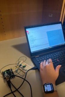
So as I mentioned before, I was almost done with my p5.js part…or at least I thought so. However, I turned out running into two main problems with it, which were: 1) setting up the code so that I can go from start screen –> draw game stage –> game over stage and repeat this process, and 2) figuring out the code for connecting with Arduino + the buttons on my physical controller, which relates to the Arduino part.
Just to recap, here were the items on my to-do list from my last post:
reset + start game
Arduino connection
Building a physical game controller using Arduino
…which basically encapsulates my progress that I’ve made this week!
Moreover, here’s my initial concept and the description of interactive design:
Concept: create a dinosaur game that is upgraded to a Christmas version.
Description fo interactive design: users will be able to control and play the game by using a physical game controller.
Problem #1: reset + start game
I knew I was going to have problems with this function because I wasn’t able to figure this out for my last project, which was my midterm game. However, because this is the final assignment, I was determined to get to the bottom of it and tackle this challenge. Unfortunately, my game kept jumping straight to the “game over” screen from the “start” screen when I tried to replay it after my gingerbread man “died,” when I was trying to get it to go through the order of the three stages I had, which were the “start” screen, “draw game” screen, and then “game over” screen, and looping again when I tried to replay it by pressing “backspace” button. This was a HUGE struggle I had because I was just stuck in this loop without being able to identify what was causing this; but with a lot of hours spent discussing and debugging with Jack and professor Shiloh, I realized that it was a combination of different mistakes in my code, such as adding “noLoop()” at the end of this part of the code:
for (let c of chimneys) {
      c.move();
      c.show();
      if (gingerbreadman.hits(c)) {
        gameState = "gameOver";
      }
as well as realizing that the main reason why my game immediately jumped to “game over” stage was because the gingerbread man had already ran into the chimneys even before the game “reset” since I never redrew the chimneys despite having a redraw function for the gingerbread man. This was why I couldn’t replay the game, for my code made it so that when the gingerbread man hits a chimney, the game will immediately be over! So I added the following code in “function setup(),” which successfully redrew the chimneys and thus erasing all the previous chimneys that were being drawn in the previous stage:
chimney1 = new Chimney1();
chimney2 = new Chimney2();
While it was a simple and easy mistake, it took me such a long time to realize it.
Problem #2: Arduino connection
Now, this was another struggle of mine that I wasn’t able to solve fully in my last assignment where I had to connect Arduino with p5.js. Thankfully, I had Jack to help me again, and he walked me through the initial setup of connection, etc. During this I realized that:
I don’t need to assign a specific key from my keyboard to the button when I was transmitting my p5.js code from keyboard keys to button pins on Arduino.
I don’t need to use a third party application/installation to call on the serial port library.
Serial port is like a “tube,” where ideally information from both p5.js and Arduino will transmit to each other – this will ensure that I’m receiving the correct data from both sides, even if I’m only feeding information from one platform to other (in this case, from Arduino to p5.js).
Here’s the code highlight for connecting Arduino and p5.js:
function readSerial(data) {
  ////////////////////////////////////
  //READ FROM ARDUINO HERE
  ////////////////////////////////////

  if (data != null) {
    // make sure there is actually a message
    // split the message
    let fromArduino = split(trim(data), ",");
    // console.log(fromArduino);
    // if the right length, then proceed
    if (fromArduino.length == 3) {
      // only store values here
      // do everything with those values in the main draw loop
      GREEN = fromArduino[0];
      RED = fromArduino[1];
      BLUE = fromArduino[2];
    }

    //////////////////////////////////
    //SEND TO ARDUINO HERE (handshake)
    //////////////////////////////////
    let sendToArduino = GREEN + "," + RED + "," + BLUE + "\n"; //?
    writeSerial(sendToArduino);
  }
}
It was interesting to learn that the “fromArduino.length” indicates how many variables I’d like to establish, and that each will be an array ([]) numbering from 0, which meant that in this case, it’d be arrays 0,1,2. I also realized that each array should be separated by a comma.
This was also a function that was crucial/necessary in setting up the connection:
 let serial; // constructing variable for serial port library

...

 function keyPressed() {
    if (key === "A") {
    // important to have in order to start the serial connection!!
    setUpSerial();
    }
  }// end of keyPressed
Through this method that Jack taught me, I didn’t run into the constant error messages of how “p5.js port is not a serial library,” which was the problem I had for my last assignment.
Problem #3: Building a physical game controller using Arduino
Now, this was honestly the most interesting and exciting part of my final project, which was surprising because I was the most intimated with this aspect before I began.
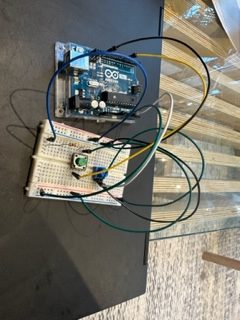
At first, I was going towards a totally wrong direction; all of my button setups on my breadboard were completely incorrect, so I had to fix all of them after Jack showed me this page, which basically showed how to construct buttons on Arduino. So I repeated that for all of my 3 buttons, which carried out the “START GAME,” “RESTART GAME,” and “JUMP” functions. Once I was done building the circuit, I also made sure to construct them in p5.js by doing the following:
let GREEN = 0; //JUMP key
let RED = 0; //RESTART GAME key
let BLUE = 0; //START GAME key
I also realized that it’s best to use three = sign, and that I can simply set the button code so that it’s either pressed or not pressed, which were 1 or 0 respectively. This led me to create a code like the following for the three buttons:
function drawGame() {
    //make it so that when you press the up arrow, the gingerbread man will jump
    if (GREEN === "1") {
      gingerbreadman.jump();
      jump.play();
    }
Now once I was done with p5.js, I moved onto my Arduino code, where I constructed the pinMode for each button and digitalRead functions for each. Here’s the Arduino code:
void setup() {
  Serial.begin(9600);
  pinMode(10, INPUT);
  pinMode(11, INPUT);
  pinMode(12, INPUT);
  // start the handshake
  while (Serial.available() <= 0) {
    Serial.println("0,0,0"); // send a starting message
    delay(300);            // wait 1/3 second
  }
}

void loop() {
  // wait for data from p5 before doing something
  while (Serial.available()) {
    int GREEN = Serial.parseInt();
    int RED = Serial.parseInt();
    int BLUE = Serial.parseInt();
    if (Serial.read() == '\n') {
      int GREEN = digitalRead(10);
      delay(1);
      int RED = digitalRead(11);
      delay(1);
      int BLUE = digitalRead(12);
      delay(1);
      Serial.print(GREEN);
      Serial.print(',');
      Serial.println(RED);
      Serial.print(',');
      Serial.println(BLUE);
    }
  }
}
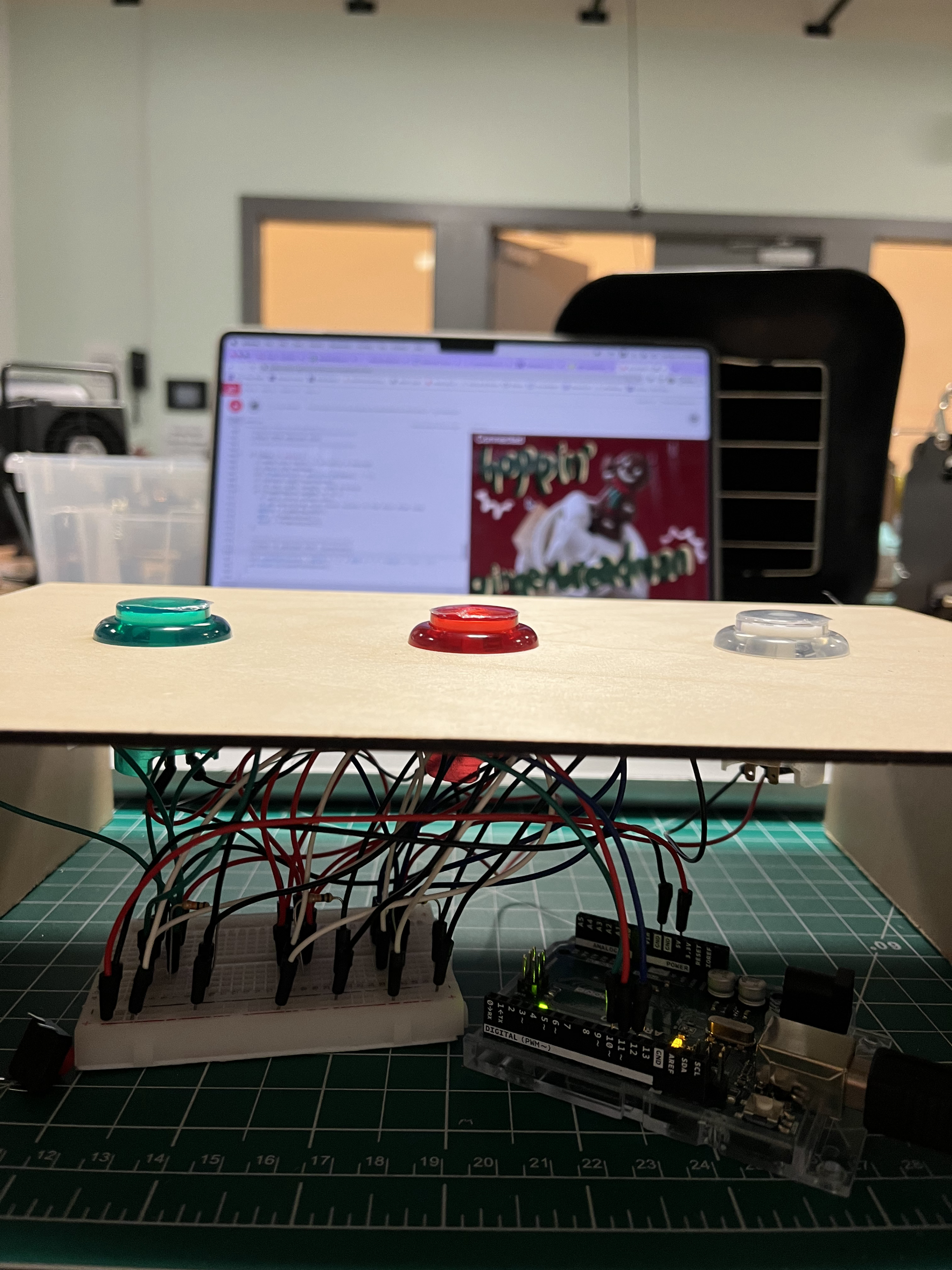
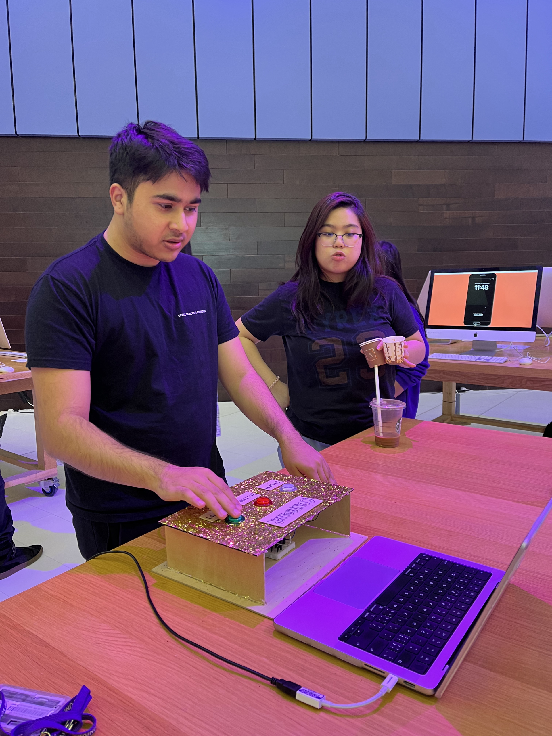
Thankfully, till here it was successful! I was almost done…but I still had to create a physical controller that was an extension of the Arduino buttons that I had already. For this, I used thin wooden boards to create a controller box; I used the laser cutter, saw, and the exacto knife to cut the pieces that made up the box as well as the 3 circles for my 3 larger buttons (green, red, and white). Then I learned how to solder from Maryam and Vivianna (special shoutout to both of them!), which was honestly the BEST thing I’ve tried in this course, haha. Here’s a photo of what my controller looked like at this point before decoration:
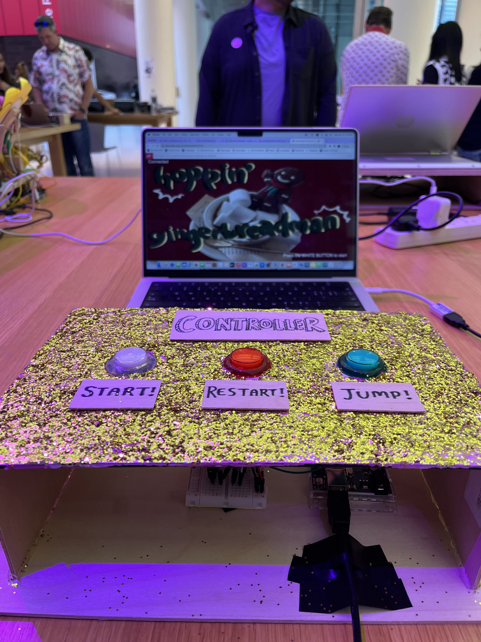
It was so satisfying to test the code and find out that your large buttons successfully work! Once that was all done, I simply hid the Arduino breadboard and the microcontroller inside the box, and decorated the wooden box with gold glitter, paint, and glue as well as tags that indicated which button was for what function.
What I’m proud of:
Now that I’ve described the problems I’ve struggled with, here are some things that I was proud of! For creating the actual physical game controller, I ended up designing, crafting, and putting everything together myself from scratch to finish because I was running out of time. I honestly didn’t expect myself to finish it this quickly, and also didn’t expect myself to have no struggles with soldering because it was something that I was completely oblivious of. I was also proud of myself for figuring out and overcoming the challenges that I previously weren’t able to conquer before, such as connecting Arduino to p5.js and being able to make my game be repeatable! I was also proud of the decoration that I did, which is shown below:
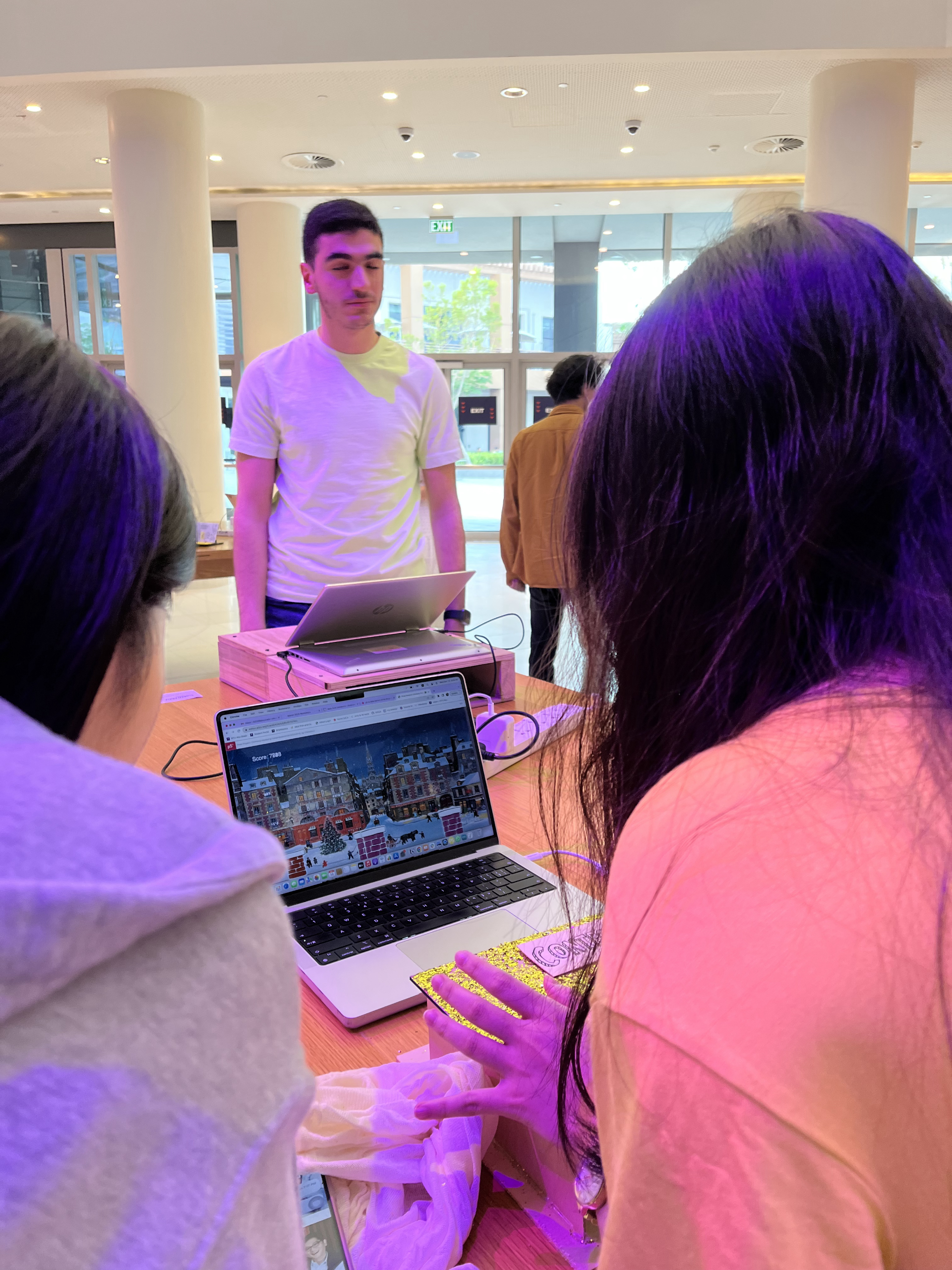
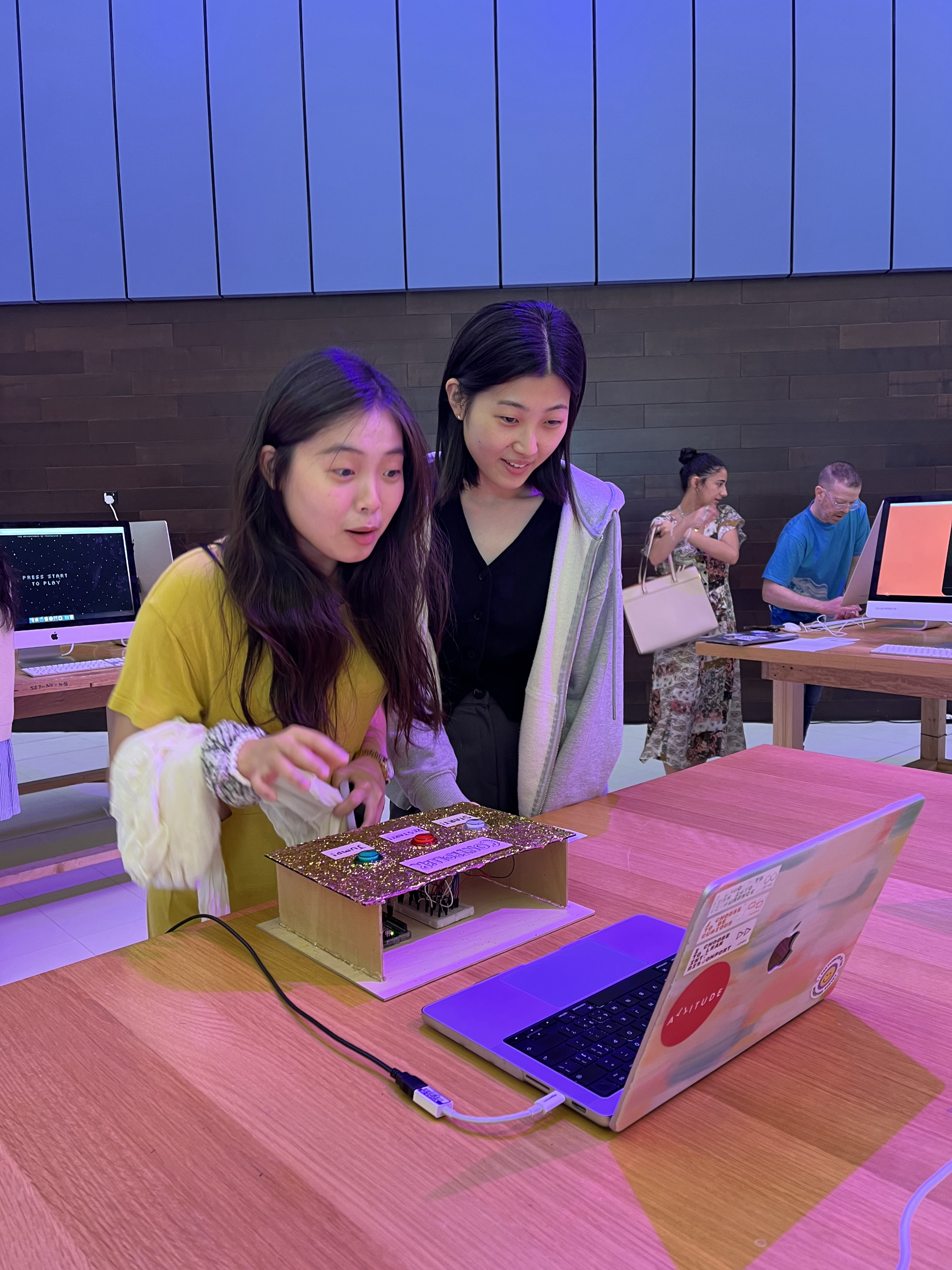
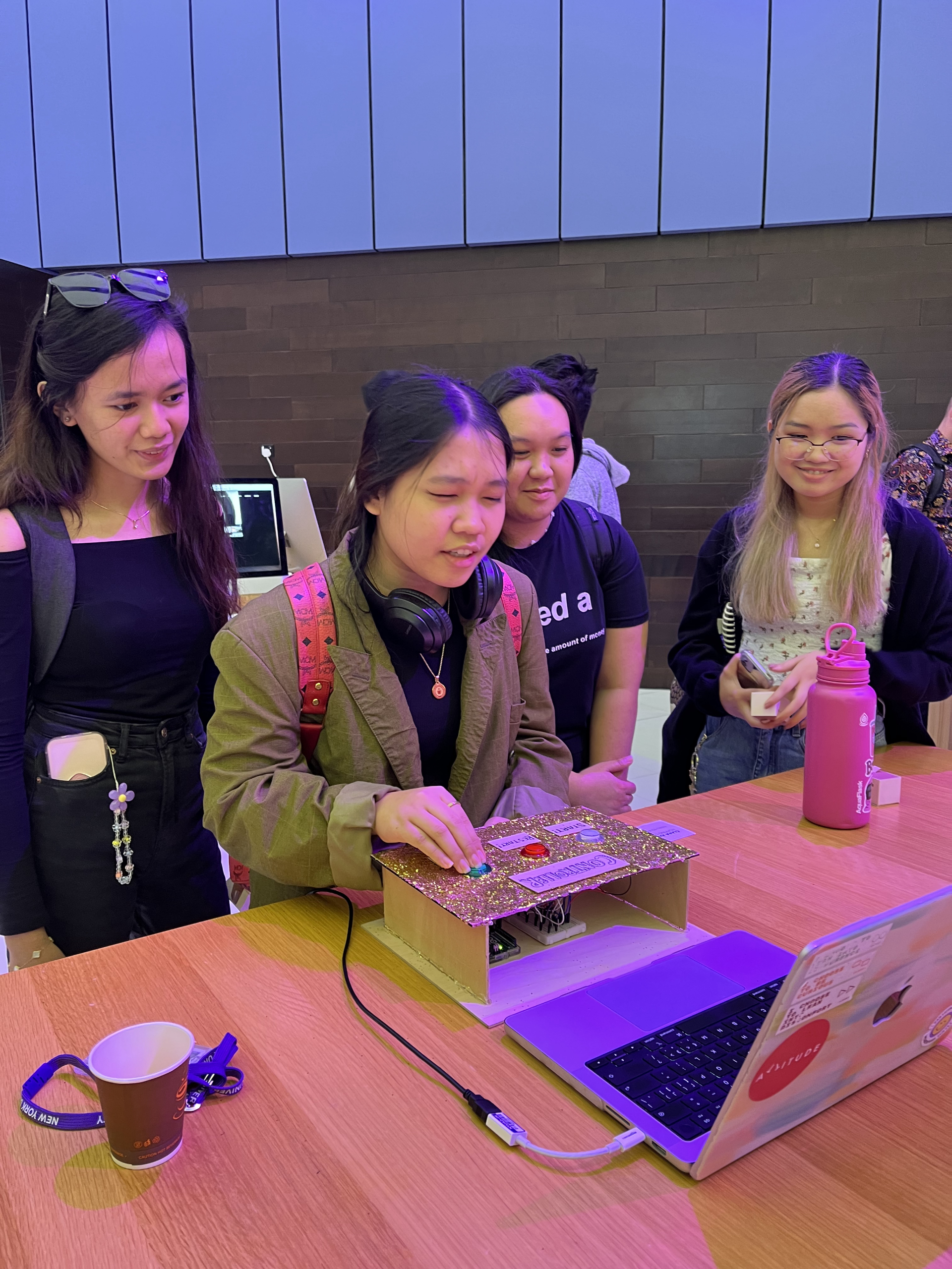
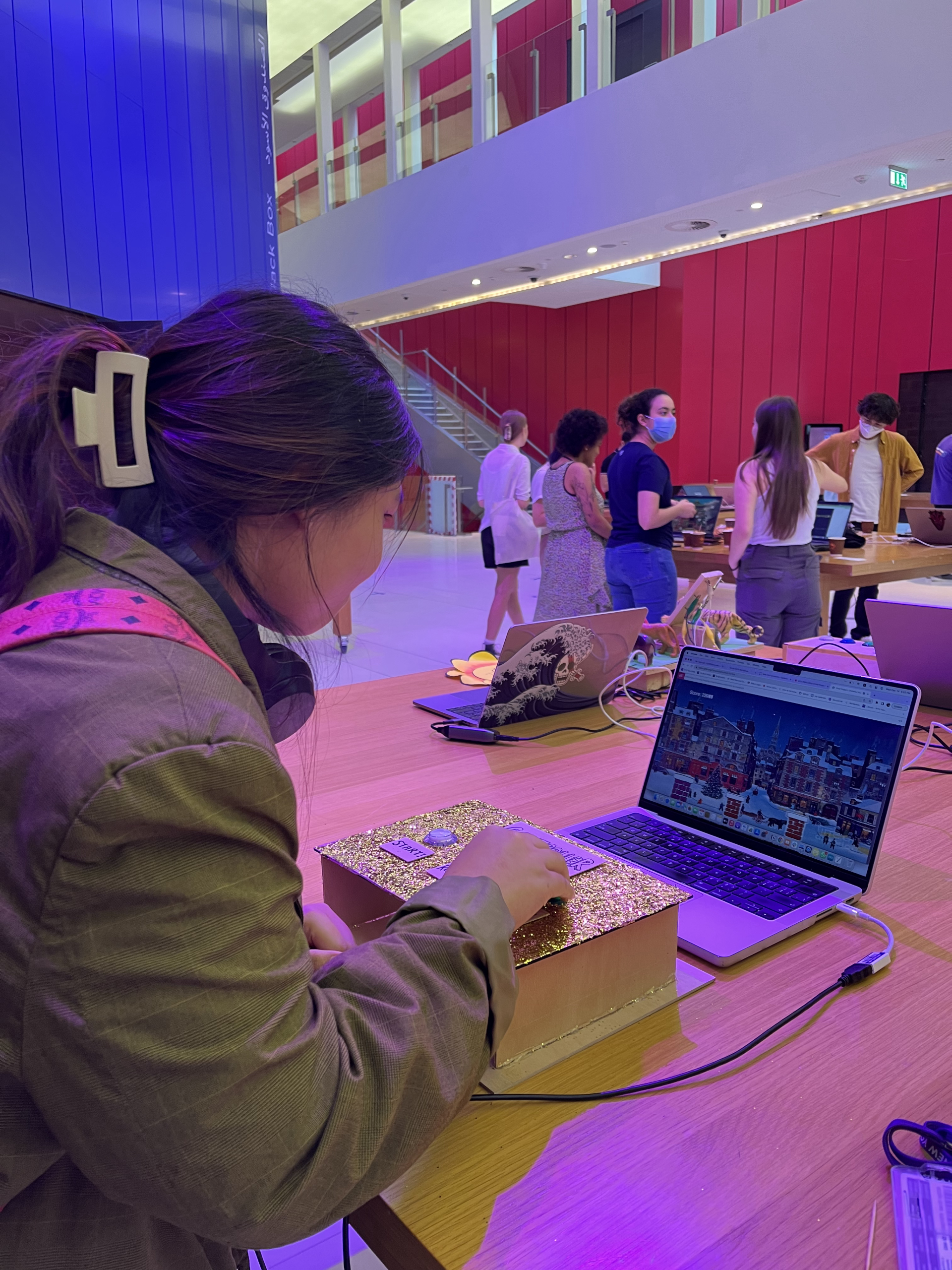
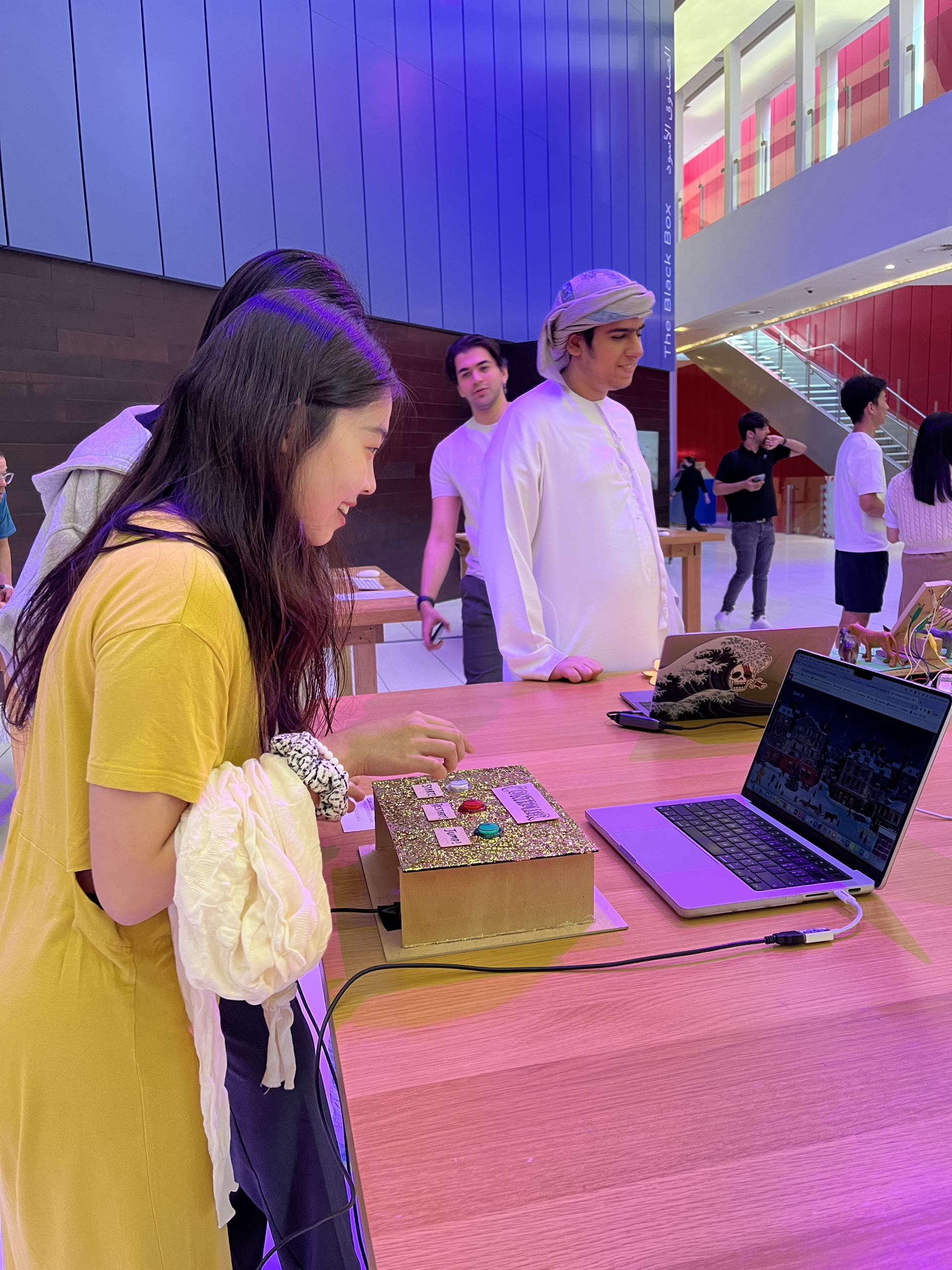
User experience/showcase:
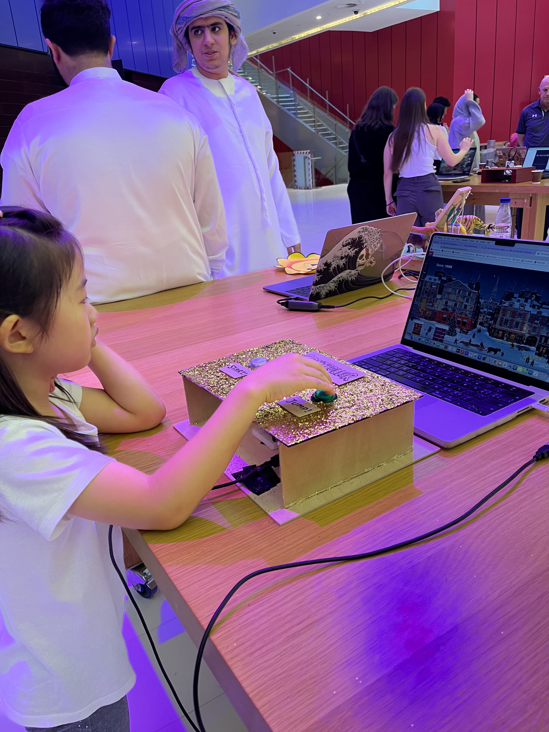
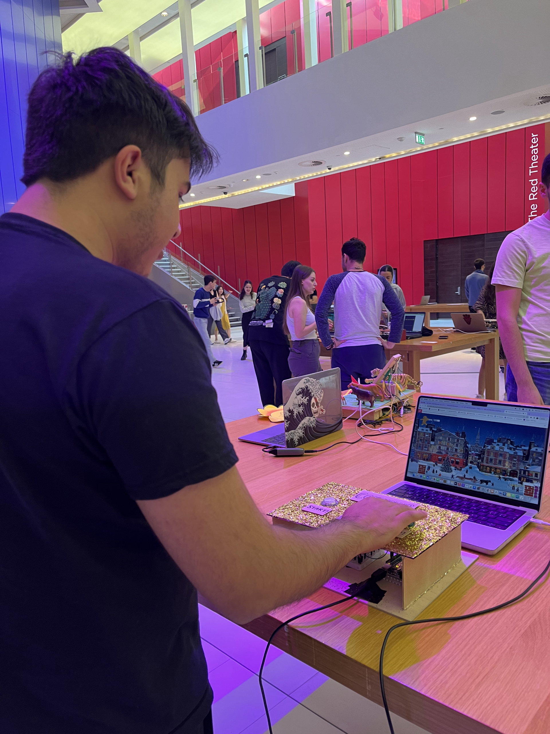
The showcase was a blast! Although there were some unexpected errors at times (ex. my game site crashing and having to reload every 20 minutes or so or my game starting to lag after going past a certain score point), I was happy to see my users actively interacting with the game and just having fun. 🙂 Here are some photos that I took of them playing my game after getting their consent:
One thing that kept coming up was having no limits to how much the users could make their gingerbread man jump; many of them figured out that they can use this to “cheat” the game because they could just make the gingerbread man constantly be up in the air by pressing down on the button continuously, which lagged the game but also meant they could go on forever. So I thought it’d be necessary to place some kind of a limit either for the amount of jumps they can do, the height that they can reach, or putting a time limit on the game.
Another thing that I thought I could try was making it like a flappy bird game instead of a dinosaur game, because the chimneys would have been perfect as a flappy bird game! I could’ve placed the chimneys at both the bottom and top of the screen and have the users try to float the gingerbread man between them, and that would’ve been cool as well.
Aaaaand that’s it! That’s a wrap of this course and the semester. 🙂 Huge thanks and props to our professor, the lab assistants, Jack, and our class for working altogether so hard for the past four months, and I hope to work with them again in future IM classes as well! But for now, holidays are awaiting all of us eagerly. 😉
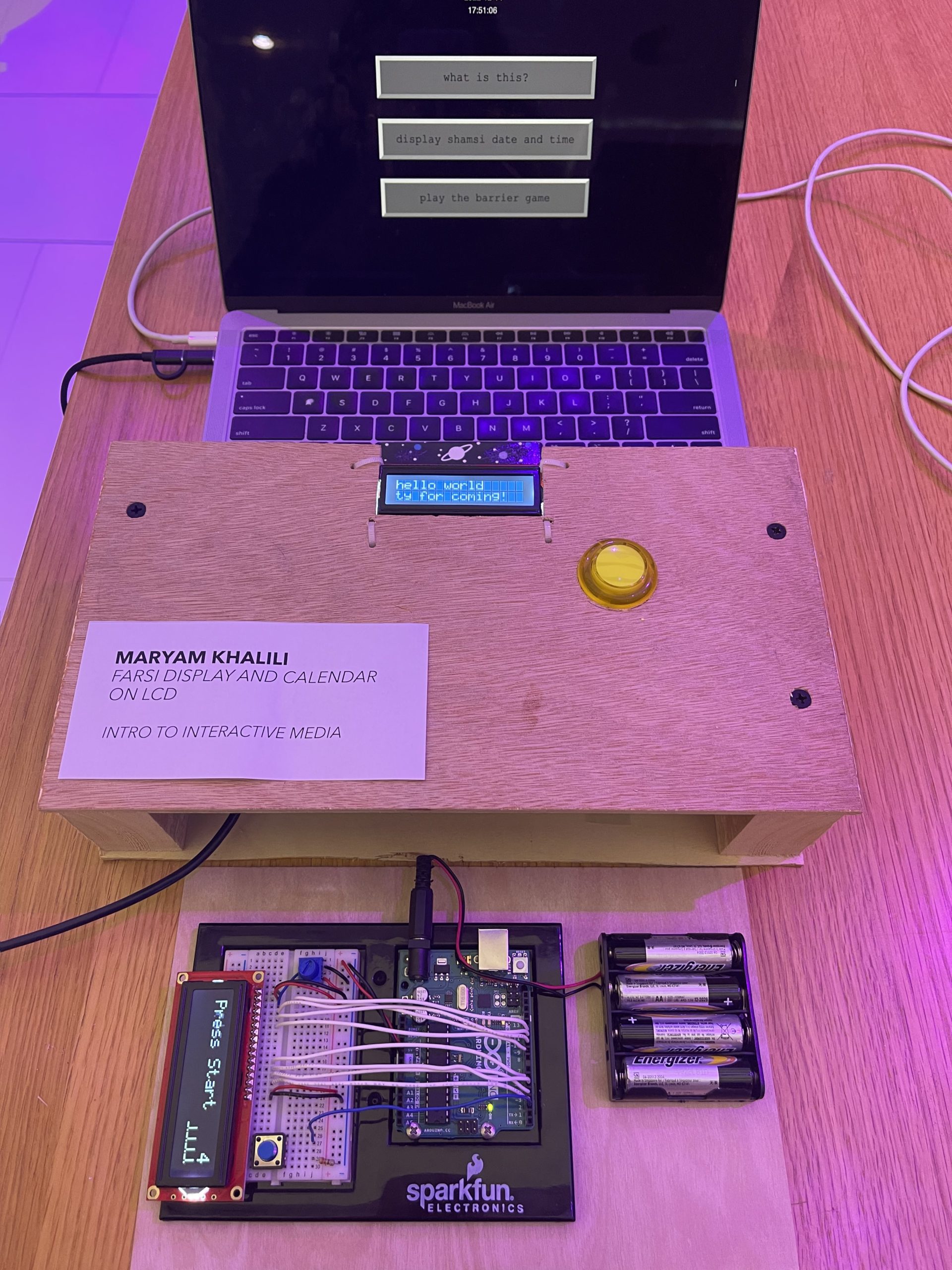
Farsi Display on Arduino: calendar and a dinosaur game
Describe your concept
The premise of my project is very simple: construct and display Persian/Arabic letters on Arduino LCD (16×2), with the main purpose of displaying the Persian calendar date (Hijri Shamsi) and making a little dinosaur game where the barriers are Farsi letters (or a block).
How does the implementation work?
Description of interaction design
Description of Arduino code
Description of p5.js code
Description of communication between Arduino and p5.js
Interaction design:
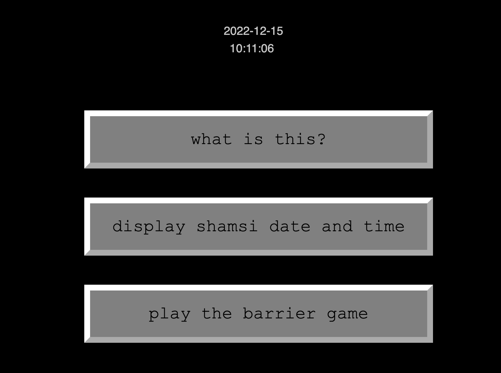
p5.js is where the user input is stored and communicated to Arduino over serial operations. P5.js would take input based on the button the user clicks:
Arduino code:
Arduino code reads serial input and does one of three things below:
Display a welcome text to the user
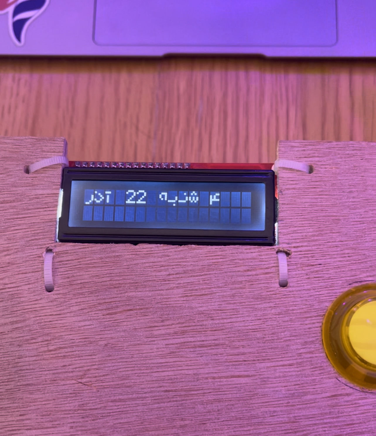
Construct Farsi letters and display the Shamsi date on the LCD
Call the main game function
For the game, I consulted the code from the Arduino project hub I used some functions for moving the barriers to the left of the screen and controlling the collision.
Establishes the handshake between p5 and Arduino. Based on the button the user clicks, p5 sends a unique digit to Arduino and Arduino will take it from there.
What are some aspects of the project that you’re particularly proud of?
My original idea was to make a Farsi letters reshaper/constructer only, but I decided to bring more interaction to the project by adding a little game. I enjoyed making the byte arrays for different Farsi letters and refining them so that they look better when put together in a word. I’m also proud of the little box I made with the help of Professor Shiloh. I had never worked with wood before and it was last minute but it turned out fine and people found it intuitive to interact with the button and LCD once they were made into the box.
What are some areas for future improvement?
There are two limitations:
The 16×2 LCD is very limited: in terms of how many custom characters you can make (only 8) and also in terms of how many characters it displays in general (32). A bigger LCD would solve this problem and improve the project.
Serial input only reads English: I tried sending Farsi letters over Serial communication which resulted in a gibberish serial read by Arduino. It might be possible to send English input and transliterate it in the Arduino and display it, but not all letters can be mapped.
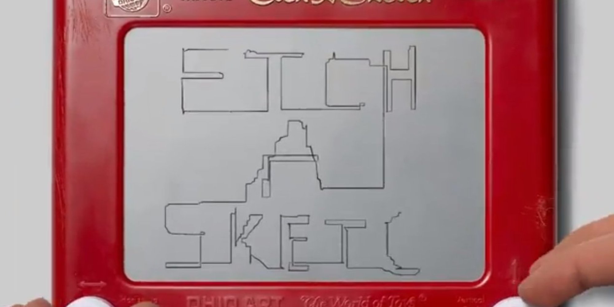
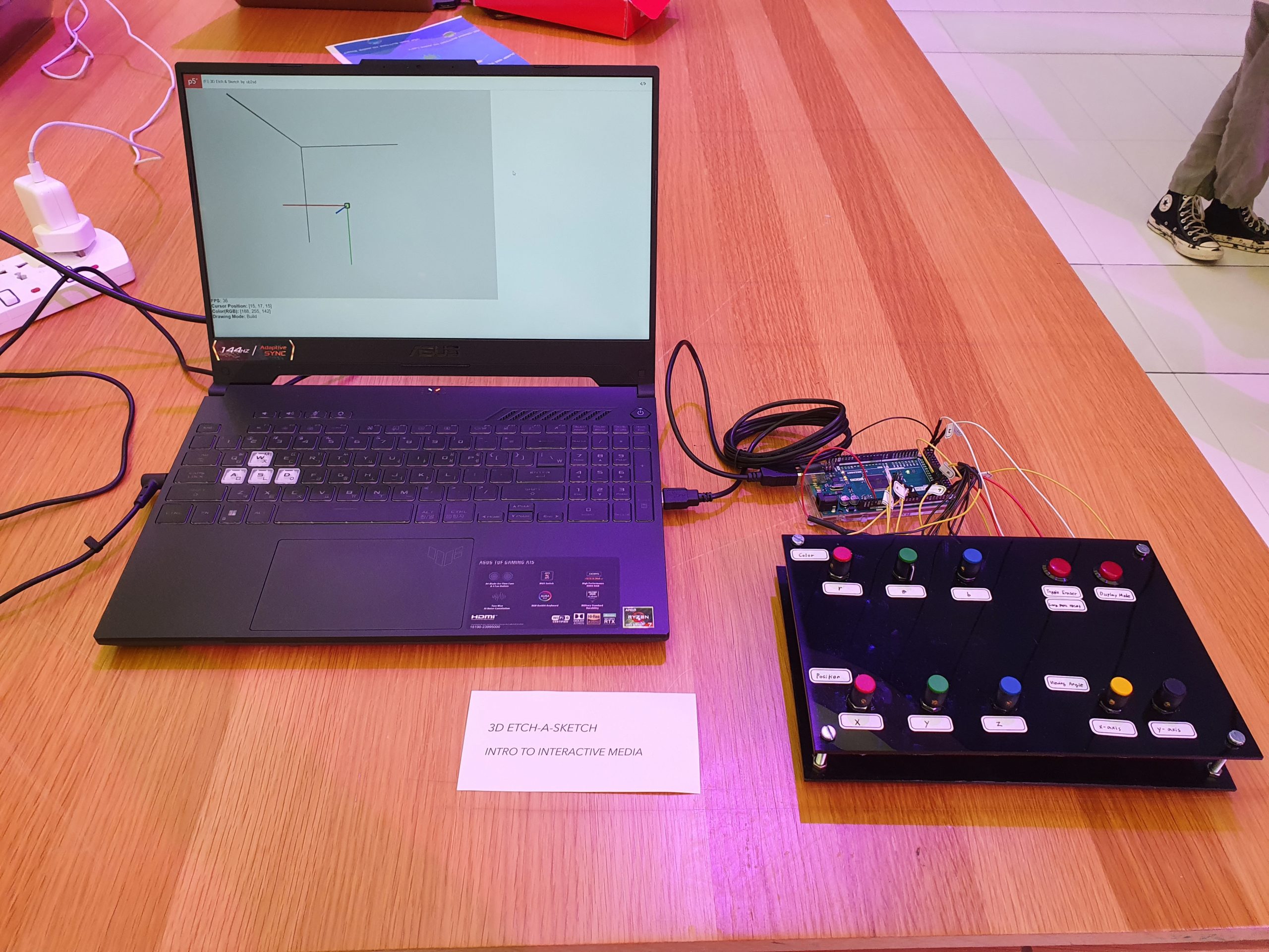
My project is inspired by Etch-a-sketch, a simple drawing tool with just two knobs that control the x and y coordinates of a drawing cursor. My initial thought was to create a digital replica of this tool, however, Prof. Shiloh made me I decided to challenge myself: add another drawing axis so it becomes a 3D drawing tool. It is a 3D-Etch-a-Sketch.
Interaction Design
3D-Etch-a-Sketch means that there are at least 3 knobs (potentiometers) for a drawing cursor, each for x, y, and z coordinate. Also, since the drawing can occur in front or behind a previous drawing, there need to be a way to shift/rotate the viewing angle to see where the user is drawing. So I added 2 more knobs for rotation of viewing angle in x-axis and y-axis.
In addition to this, I thought to myself, why not color, so I added 3 additional knobs for r, g, b values of drawing cursor’s color.
Two more switches (buttons) are added for eraser/reset function and change of display mode. Those functionalities will be described later.
As a result, my final product looks like the below image. A black control panel with 8 knobs and 2 buttons. Laptop screen is used to display the drawings.
Arduino Code
The Arduino code reads values from sensors, stores converted or raw values into different variables, convert, and send values to p5.js. It also receives whether p5.js finished a reset process. The detail is as the following:
Sensors: 8 potentiometers and 2 switches (buttons)
3 potentiometers: x, y, z coordinate of the drawing block (0-30)
3 potentiometers: R, G, B value of the drawing block (0-255)
2 potentiometers: x, y angle of rotation of entire drawing (0-360)
1 switch: choose among displayAll/disableIndicators/disableAll
displayAll: display 3D space indicators and block outline
disableIndicators: disable 3D space indicators
disableAll: disable 3D space indicators and block outline
1 switch: toggle eraser mode & long press to reset all
Build: normal drawing block
Remove: invisible drawing block (erase blocks)
Reset Warning: press 1.2 seconds to enter, warn that if pressing is continued, entire drawing will be removed
Reset: continued press (total 2.4 seconds) to enter, clear all blocks
show() {
  let fd = this.voxelSize * this.d; // used to go to next row
  let cd = fd / 2 + this.voxelSize / 2; // used to center voxel display
  translate(-cd, -cd, -cd);
  ...
  for (let i = 0; i < this.d; i++) {
    translate(this.voxelSize, 0, 0);
    for (let j = 0; j < this.d; j++) {
      translate(0, this.voxelSize, 0);
      for (let k = 0; k < this.d; k++) {
        translate(0, 0, this.voxelSize);
        this.voxels[i][j][k].show();
      }
      translate(0, 0, -fd);
    }
    translate(0, -fd, 0);
  }
  ...
}
This code displays each blocks (31 x 31 x 31) in the correct position. This code is nice because it is quite intuitive yet powerful.
Arduino:
void setEraserMode() {
  bool switchState = !digitalRead(btn_eraser);
  if (switchState) { // on
    unsigned long currentMillis = millis();
    if (!prevEraserSwitchState) { // when off > on
      eraserMillis = currentMillis;
    } else if (currentMillis - eraserMillis >= eraserTriggerDelay) { // 1.2 sec press: promptReset
      if (currentMillis - eraserMillis >= eraserTriggerDelay*2) {  // 2.4 sec press: resetAll
        eraserMode = 3;
      } else {
        eraserMode = 2;
      }
    }
  } else { // off
    if (prevEraserSwitchState) { // when on > off
      eraserMode = !eraserMode; // 0 becomes 1, nonzero becomes 0
    }
  }
  prevEraserSwitchState = switchState;
}
This code lets a switch(button) to serve multiple functions. You can press to toggle between two values (0 and 1) and, when pressed long, this code goes through different stages (3 and 4). If released in any time during higher stages, the value resets. This code is used in setting the eraserMode/reset.
Physical component:
The panel and casing seems to be made nicely. It is clean and sturdy.
Future Improvements
During the showcase, I realized that there could be a few improvements in my project:
Visible indication of color changes. People tend to turn knobs slowly (partly due to it being a bit stiff), and it is often that people do not realize the color changes on the screen. They move on to other visibly interactive sensors.
Removal of reset warning. Because reset warning shows a drastic change in view (a clear screen with warning message), people do not see it as a warning sign but instead an indication of actual reset. Also, people tend to not press the button for long period (1~ sec), so it may be better to have 2~2.5 sec delay with no reset warning.
Improved stabilization of analog read. Although there were multiple measures of making analog read stable (delay, double check, average, heat shrink tubing, etc.), there were noises in reading and it was difficult to make the drawing precise.
Previously, as a part of the progress, I posted the following video.
The video is recorded using a debug mode, which is controlling interactives with keyboard. My physical component was incomplete to create a user testing video back then.
However, I completed my physical component before the showcase.
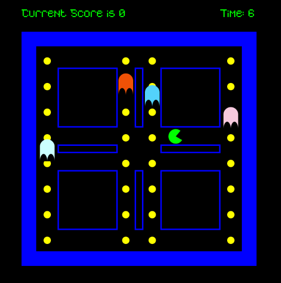
I decided for the final project to design a game that is very similar to the maze action video game, Pacman. Therefore, the main concept of my game is that there is a main character that looks like a green arc who tries to avoid the ghost enemies and eat circles, the more circles the character eats the more points he gets. The player will win the game if he or she can eat fifteen circles before bumping into one of the ghosts. On the other hand, if one of these ghosts catches the player before reaching a score of 15 circles eaten, then the player will lose the game.
I decided to create a game with this concept because I enjoyed playing Pacman as a kid and wanted to explore if I might be able to make a game that is very similar to my favorite childhood game. To make this project even more interesting, I decided to change some of the instructions of the normal Pacman game. If the main player eats a circle, the circle should change colors from yellow to red. Moreover, the main player can eat a circle more than one time.
This design for the game was implemented in my midterm project. For the final project, I decided to add more stuff to this game and make it controllable using hardware devices. Therefore, I created a physical structure that contains the hardware devices which control the Pacman game. These devices mainly include a joystick and a button and you can see the final output in the video below.
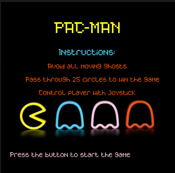
Description of Interaction Design
The interaction between the user and the game using hardware was done using mainly a joystick and a button. At first, the user will only see the main menu screen of the game that you can see attached below.
By pressing on the blue button that you can see in the image of the physical structure above, the user can start the game and move to the screen where the play screen of the game that you can see below.
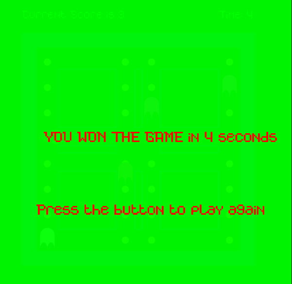
After that, the user can use the joystick to control the motion of Pacman in the game. By moving the joystick to the left PacMan will move to the left, while moving it to the right PacMan will move to the right, by moving the joystick forward PacMan will move up and by moving the joystick backward PacMan will move down. With this control of the PacMan motion the user can play the game easily and smoothly and enjoy one of the most famous classic arcade games. When the user win the game by reaching the score of 255 they will see the following screen
However, when the user loses the game they will see the following screen
By just pressing the blue button the user will be able to restart the game again.
Description of Arduino Code
The Arduino code for my final project is designed to control the joystick and the button in my game. I initialized four different pins that the Arduino code will read based on the inputs from the joystick. This is because the joystick that I am using has five different wires. One wire is connected to the ground while the other four wires are responsible for detecting the motion of the joystick in four different directions, forward, backward, left, and right. Therefore as you can see in this section of my Arduino code I am reading the values of these four different pins in Arduino. I decided to use the pull-up resistor when defining these pins to ensure that the pins are all set to 1 whenever the switch is turned off.
void loop() {

  switchState=digitalRead(12);

  UP = digitalRead(upPin);
  RIGHT = digitalRead(rightPin);
  LEFT = digitalRead(leftPin);
  DOWN=digitalRead(downPin);

  Serial.print(UP);
  Serial.print(',');
  Serial.print(DOWN);
  Serial.print(',');
  Serial.print(RIGHT);
  Serial.print(',');
  Serial.print(LEFT);
  Serial.print(',');
  Serial.println(switchState);
  delay(100); // add some delay between reads
}
Furthermore, I read another value in the Arduino code which is the value of the blue button to determine the state of the switch at any time. After that, I print the values of the four joystick pins as well as the value of the blue button and separate them by commas to send them to p5.js. I added delay between the reads to ensure that there is no unnecessary errors due to fast reads.
Description of P5.js code
The p5.js code contains information about the pacman game. It contains four main states which are the main menu, play state, win and loss states. I showed images of these states above, and to move from one state to another I created a state machine. To come up with the pacman and ghosts in the game I used two different classes. Inside the pacman class I created some functions to draw the pacman, move the pacman and check if the pacman hits any of the boundaries that I draw on the screen.
To create the ghosts in the game I created another class called ghost, in this class I also created functions to draw the ghosts and place them in random positions and move them up and down. I also control the speed of the ghosts in this class. After that, I created a function that detects whenever the pacman hits one of the ghosts to detect when the user is supposed to move to the loss state. I show the code for calling these functions in the playscreen below.
  for (let k = 0; k < 4; k++) {
    ghost[k].moveEnemy();
    ghost[k].checkBounds();
    ghost[k].drawEnemy();
    //check if the main player will hit the enemy
    ghost[k].checkLossState(mainCharacter.xPos, mainCharacter.yPos);
  }
  //draw main character and call different functions of the class
  mainCharacter.drawPlayer();
  currTime = int((millis() - prevTime) / 1000);
  textSize(15);

  text("Time: " + currTime, 300, 30);

  mainCharacter.checkBoundsConditions();
  mainCharacter.movePlayer();
  mainCharacter.eatCircles();
  mainCharacter.displayCount();

  mainCharacter.checkWinningState();
}
Communication between Arduino and p5.js
P5.js should also read 4 different values from arduino which will be the UP position, DOWN position, LEFT position and RIGHT position. If any of these values is zero then in p5.js I will write if statements to move the pacman towards this direction. For instance, if UP is zero then pacman moves towards the up direction.
In addition to this, the p5.js program will read another value from Arduino which will be the current state of the blue button. If the button is pressed, then in the p5.js I can move from one game state to another. For example, if I am in the main menu screen and would like to move to the game screen then I can easily do this by just pressing the blue button.
As a result, in the Arduino part of my project, I will be writing to the serial the 5 different values that I want to send to p5.js which are the four different directions along with the switch state and will separate these values by commas so that they could be easily read in p5.js. I display below the finalized version of my game with sounds implemented in it.
What are some aspects of the project that you’re particularly proud of?
This project especially the hardware and the physical computing part of it was very challenging for me. I spent so much time drilling wood and connecting wooden pieces together, therefore I think that the most challenging part of my project is mainly building the physical structure to house the different hardware devices. Although it was not easy, I am very proud of the result that came out of it because I really like how it looks right now and you can see it in the video that I attached above. Furthermore, I discuss in detail how I came out with this output in my previous post which shows the progress towards my final project.
What are some areas for future improvement?
I believe that I could add more hardware stuff to the game in the future. I would be adding some indicators like LED lights that will display to the user their progress in the game. For instance, if the user needs 25 points to win the game, I will have 5 LED lights and each LED light will light up after the user obtains 5 points. So after the user get the 25 points, he will have the 5 lights all being on.
Furthermore, I would also like to improve more on the software part of the game. This will be done by making the yellow circles disappear when the user goes over them. This will avoid having a glitch in the game where the user can go over the same yellow circle multiple times and still win the game. Overall, I really enjoyed this project and believe that I learned so much from it. I hope I can design more creative things with this knowledge in the future.
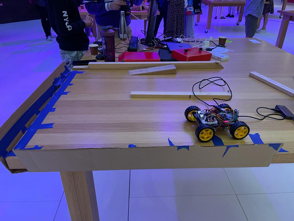
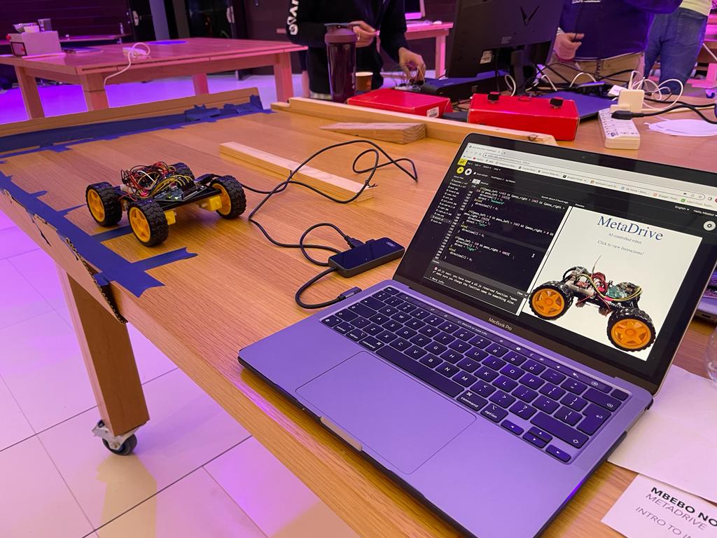
The concept was to use AI to control an arduino robot. Using the machine learning module handsfree.js, I mapped different hand gestures and finger positions to control an arduino robot I created. The arduino robot had 4 DC motors for movement, 1 ultrasonic sensor to measure the distance of nearest obstacles, 1 buzzer and two LED lights.
Interaction Design:
A video webcam feed in p5js maps your fingers and palms, calculates the positions of the two hands and sends the data to arduino. Based on the palm positions, arduino decides whether to move forward, backward, left or right. Arduino calculates the distance between the robot and the nearest obstacle ahead of it and sends the data to p5js, which then displays the distance to you.
Also, by pinching your index fingers in p5js, you’re able to increase and decrease the speed of the DC motors. Anytime your start the webcam in p5js, this sends data to arduino and it plays a sound using the buzzer to signal readiness to receive the data.
Arduino Code:
The arduino code uses two libraries: “NewPing.h” and “TimerFreeTone.h”. The NewPing library makesre using the ultrasonic sensor easy and convenient. The TimerFreeTone also simplifies the use of the tone function and makes working with the buzzer seamless.
The additional header file labeled “pitches.h” contains sounds that are played when arduino is ready to receive data from p5js.
#include "pitches.h"
#include <NewPing.h>
#include <TimerFreeTone.h>

//left_wheels
const int left_ain1Pin = 3;
const int left_ain2Pin = 4;
const int left_pwmAPin = 5;

//left wheels speed
int leftspeedA=200;


//right wheels
const int right_bin1Pin = 8;
const int right_bin2Pin = 7;
const int right_pwmBPin = 6;

//right wheels speed
int rightspeedB=200;


//ditance sensor
const int trig = 9;
const int echo = 10;
const int max = 100;
//distance
NewPing dist(trig, echo, max);
int direct;


//leds
int greenlight = 2;
int redlight = 12;


//state machine for timer
unsigned long previousMillis;
long interval = 1000;

//foward motion function
void forward(){
  analogWrite(left_pwmAPin, leftspeedA);
  analogWrite(right_pwmBPin, rightspeedB);

  digitalWrite(left_ain1Pin, LOW);
  digitalWrite(left_ain2Pin, HIGH);

  digitalWrite(right_bin1Pin, HIGH);
  digitalWrite(right_bin2Pin, LOW);
}

//backward motion function
void backward(){
  analogWrite(left_pwmAPin, leftspeedA);
  analogWrite(right_pwmBPin, rightspeedB);

  digitalWrite(left_ain1Pin, HIGH);
  digitalWrite(left_ain2Pin, LOW);

  digitalWrite(right_bin1Pin, LOW);
  digitalWrite(right_bin2Pin, HIGH);
}

//left motion function
void left(){
  analogWrite(left_pwmAPin, leftspeedA);
  analogWrite(right_pwmBPin, rightspeedB+50);

  digitalWrite(left_ain1Pin, LOW);
  digitalWrite(left_ain2Pin, LOW);

  digitalWrite(right_bin1Pin, HIGH);
  digitalWrite(right_bin2Pin, LOW);
}

//right motion function
void right(){
  analogWrite(left_pwmAPin, leftspeedA+50);
  analogWrite(right_pwmBPin, rightspeedB);

  digitalWrite(left_ain1Pin, LOW);
  digitalWrite(left_ain2Pin, HIGH);

  digitalWrite(right_bin1Pin, LOW);
  digitalWrite(right_bin2Pin, LOW);
}

//stop all movements
void stop(){
  analogWrite(left_pwmAPin, leftspeedA);
  analogWrite(right_pwmBPin, rightspeedB);

  digitalWrite(left_ain1Pin, LOW);
  digitalWrite(left_ain2Pin, LOW);

  digitalWrite(right_bin1Pin, LOW);
  digitalWrite(right_bin2Pin, LOW);
}

//playing christmas themed songs as the car moves
void play(){
  int tempo = 180;
  int notes = sizeof(melody) / sizeof(melody[0]) / 2;

  // this calculates the duration of a whole note in ms
  int wholenote = (60000 * 4) / tempo;

  int divider = 0, noteDuration = 0;
  // iterate over the notes of the melody.
  // Remember, the array is twice the number of notes (notes + durations)
  for (int thisNote = 0; thisNote < notes * 2; thisNote = thisNote + 2) {
    // calculates the duration of each note
    divider = melody[thisNote + 1];
    if (divider > 0) {
      // regular note, just proceed
      noteDuration = (wholenote) / divider;
    } else if (divider < 0) {
      // dotted notes are represented with negative durations!!
      noteDuration = (wholenote) / abs(divider);
      noteDuration *= 1.5; // increases the duration in half for dotted notes
    }
      // we only play the note for 90% of the duration, leaving 10% as a pause
    TimerFreeTone(11, melody[thisNote], noteDuration * 0.9, 10);
  }
}

void setup() {
  Serial.begin(9600);

  pinMode(left_ain1Pin, OUTPUT);
  pinMode(left_ain2Pin, OUTPUT);
  pinMode(left_pwmAPin, OUTPUT); // not needed really

  pinMode(right_bin1Pin, OUTPUT);
  pinMode(right_bin2Pin, OUTPUT);
  pinMode(right_pwmBPin, OUTPUT);

  //leds
  pinMode(greenlight, OUTPUT);
  pinMode(redlight, OUTPUT);

  play();
}


void loop() {
  direct = dist.ping_cm();
  if(direct == 0){
    direct = 100;
  }

  Serial.println(direct);

  //reading values for p5js
  //toggles between 1 and 0 to specify which movement
  int fo = Serial.parseInt(); //controls forward movement
  int ba = Serial.parseInt(); //controls back movement
  int le = Serial.parseInt(); //controls left movement
  int ri = Serial.parseInt(); //controls right movement
  int sp = Serial.parseInt(); //controls speed

  //read the speed from p5js and assign it to the speed of the wheels
  leftspeedA = sp;
  rightspeedB = sp;

  //checking to see which direction to move as per the command from p5js

  if(fo != 0 || ba != 0 || le != 0 || ri != 0){
    //set a time stamp here
    unsigned long currentMillis = millis();

    //calculate interval between and current stamp and previous stamp
    //compare to the set duration (interval)
    long itr = currentMillis - previousMillis;
    if(fo == 1 && itr > interval){
      previousMillis = currentMillis;

      //turn green light on when moving forward
      digitalWrite(greenlight, HIGH);
      forward();
    }
    else if (ba == 1 && itr > interval){
      previousMillis = currentMillis;
      digitalWrite(redlight, HIGH);
      backward();
    }
    else if (le == 1 && itr > interval){
      previousMillis = currentMillis;
      //turn green light on when moving left
      digitalWrite(greenlight, HIGH);
      left();
    }
    else if (ri == 1 && itr > interval){
      previousMillis = currentMillis;
      //turn green light on when moving right
      digitalWrite(greenlight, HIGH);
      right();
    }
  }else{
      stop();
      digitalWrite(greenlight, LOW);
      digitalWrite(redlight, LOW);
  }
}
p5js uses two additional libraries: handsfree.js library and the webserial library. The handsfree.js is a machine learning module that enables detection of the hands, postures and hand movement. The webserial library enables serial communication between arduino and p5js.
let speed = 50;
let distance;
//handsfree module
let running = false;
let once = false;
//forward, back, left, right
let direction = [0, 0, 0, 0];
let direct;
//image
let robo;
let right;
let left;
let back;
//fonts
let rboto;
let header;
//states
let start_state = true;
let instruct_state = false;
let command_state = false;
// This is like pmouseX and pmouseY...but for every finger [pointer, middle, ring, pinky]
let prevPointer = [
// Left hand
[{x: 0, y: 0}, {x: 0, y: 0}, {x: 0, y: 0}, {x: 0, y: 0}],
// Right hand
[{x: 0, y: 0}, {x: 0, y: 0}, {x: 0, y: 0}, {x: 0, y: 0}]
]
// Landmark indexes for fingertips [pointer, middle, ring, pinky]...these are the same for both hands
let fingertips = [8, 12, 16, 20]
//preload function
function preload(){
robo = loadImage("robo.png");
header = loadFont("DiplomataSC-Regular.ttf");
rboto = loadFont("Roboto-Regular.ttf");
left = loadImage("left.jpg");
right = loadImage("right.jpg");
forward = loadImage("forward.jpg");
back = loadImage("back.jpg");
pinch_r = loadImage("right_pinch.jpg");
pinch_l = loadImage("left_pinch.jpg");
}
function setup() {
sketch = createCanvas(windowWidth, 200)
// Colors for each fingertip
colorMap = [
// Left fingertips
[color(0, 0, 0), color(255, 0, 255), color(0, 0, 255), color(255, 255, 255)],
// Right fingertips
[color(255, 0, 0), color(0, 255, 0), color(0, 0, 255), color(255, 255, 0)]
]
// #1 Turn on some models (hand tracking) and the show debugger
// @see https://handsfree.js.org/#quickstart-workflow
handsfree = new Handsfree({
showDebug:true,
hands: true,
})
handsfree.enablePlugins('browser')
handsfree.plugin.pinchScroll.disable()
handsfree.update({
setup:{
canvas:{
hands: {
$el: true,
width: 400,
height: 400
},
wrap: {
$el: true,
width: 400,
height: 400
},
video: {
$el: true,
width: 400,
height: 400
}
}
}
})
}
function draw() {
start();
instruct();
command();
}
function keyPressed()
{
if(keyCode === ENTER){
setUpSerial();
command_state = true;
}
}
function fingerPosition () {
// Check for pinches and create dots if something is pinched
const hands = handsfree.data?.hands
if (hands?.pinchState) {
// Loop through each hand
hands.pinchState.forEach((hand, handIndex) => {
// Loop through each finger
hand.forEach((state, finger) => {
if (hands.landmarks?.[handIndex]?.[fingertips[finger]]) {
// Landmarks are in percentage, so lets scale up
let x = 640 - hands.landmarks[handIndex][fingertips[finger]].x * 640
let y = hands.landmarks[handIndex][fingertips[finger]].y * 480
// Set the position of each finger
prevPointer[handIndex][finger] = {x, y}
}
})
})
}
//pinch right left index finger to decrease volume
if (hands?.pinchState && hands.pinchState[0][0] === 'released') {
if(speed > 50){
speed-=10;
}
}
//pinch right index finger to increase volume
if (hands?.pinchState && hands.pinchState[1][0] === 'released') {
if(speed < 200){
speed +=10;
}
}
//pinch right middle finger to play christmas songs
if (hands?.pinchState && hands.pinchState[1][1] === 'held') {
christmas = 1;
}else{
christmas = 0;
}
let posx_right= int(prevPointer[1][1].x);
let posy_right = int(prevPointer[1][1].y);
let posx_left= int(prevPointer[0][1].x);
let posy_left = int(prevPointer[0][1].y);
if( (posy_right < 150) && (posy_left < 150) && (posx_right > 320 && posx_left < 320) ){
direction[0] = 1;
direct = "foward";
}
else{
direction[0] = 0;
direct = "";
}
if((posy_left >240) && (posy_right > 240) && (posx_right > 320 && posx_left < 320)){
direction[1] = 1;
direct = "backward"
}else{
direction[1] = 0;
}
if((posx_left > 0 && posx_left < 160) && (posx_right > 0 && posx_right < 320)){
direction[2] = 1;
direct = "left"
}
else{
direction[2] = 0;
}
if(posx_left > 320 && posx_right > 480){
direction[3] = 1;
direct = "right"
}
else{
direction[3] = 0;
}
}
function readSerial(data) {
if(data != null){
distance = int(data);
}
let sendToArduino = direction[0] +"," + direction[1]+"," + direction[2]+","+direction[3]+","+ speed + "\n";
writeSerial(sendToArduino);
}
function windowResized() {
resizeCanvas(windowWidth, 200);
}
function sethandsfree(){
if(running == false){
buttonStart = createButton('START Webcam')
buttonStart.size(100, 100);
let scol = color(76, 187, 23);
buttonStart.style('background-color', scol);
buttonStart.class('handsfree-show-when-stopped')
buttonStart.class('handsfree-hide-when-loading')
buttonStart.mousePressed(() => handsfree.start())
// Create a "loading..." button
buttonLoading = createButton('...loading...')
buttonLoading.size(windowWidth);
buttonLoading.class('handsfree-show-when-loading')
running = true;
}
if(running == true){
// Create a stop button
buttonStop = createButton('STOP Webcam')
buttonStop.size(100, 100);
let stcol = color(128,0,0);
//buttonStop.position(windowWidth-100);
buttonStop.style('background-color', stcol);
buttonStop.class('handsfree-show-when-started')
buttonStop.mousePressed(() => handsfree.stop())
running = false;
}
}
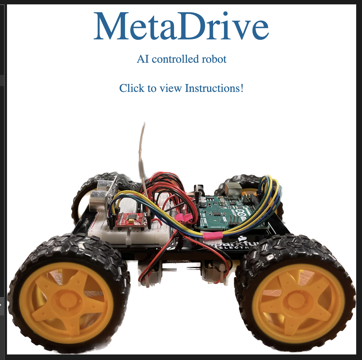
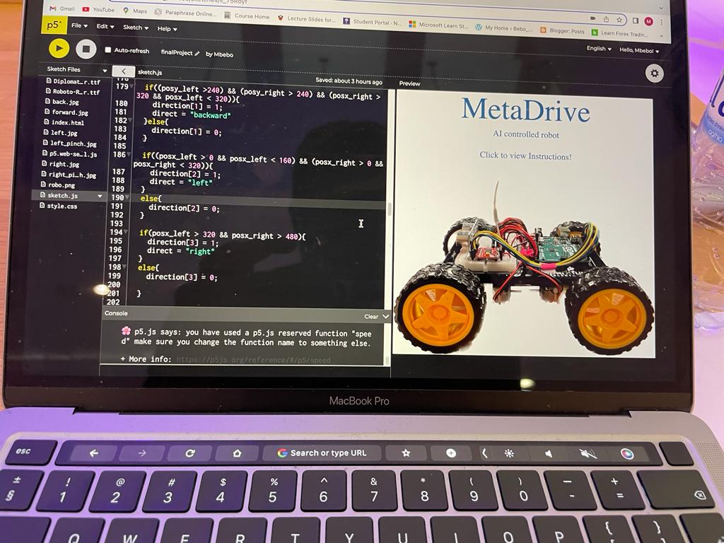
function start(){
if(start_state == true){
createCanvas(600, 600);
background(255, 255, 255);
image(robo, 0, 200, 600, 400);
//header
textSize(70);
fill(0, 102, 153);
textAlign(CENTER)
textFont("header");
text("MetaDrive", 300, 60);
//click for instructions
textSize(20);
fill(0, 102, 153);
textAlign(CENTER)
textFont("rboto")
text("AI controlled robot", 300, 100);
text("Click to view Instructions!", 300, 150);
}
}
function instruct(){
if (instruct_state == true){
createCanvas(600, 600);
background(255, 255, 255);
textSize(40);
fill(0, 102, 153);
textFont("header");
text("INSTRUCTIONS", 300, 30);
textAlign(LEFT);
textSize(20);
textWrap(WORD);
textFont("rboto")
fill(0);
//movement
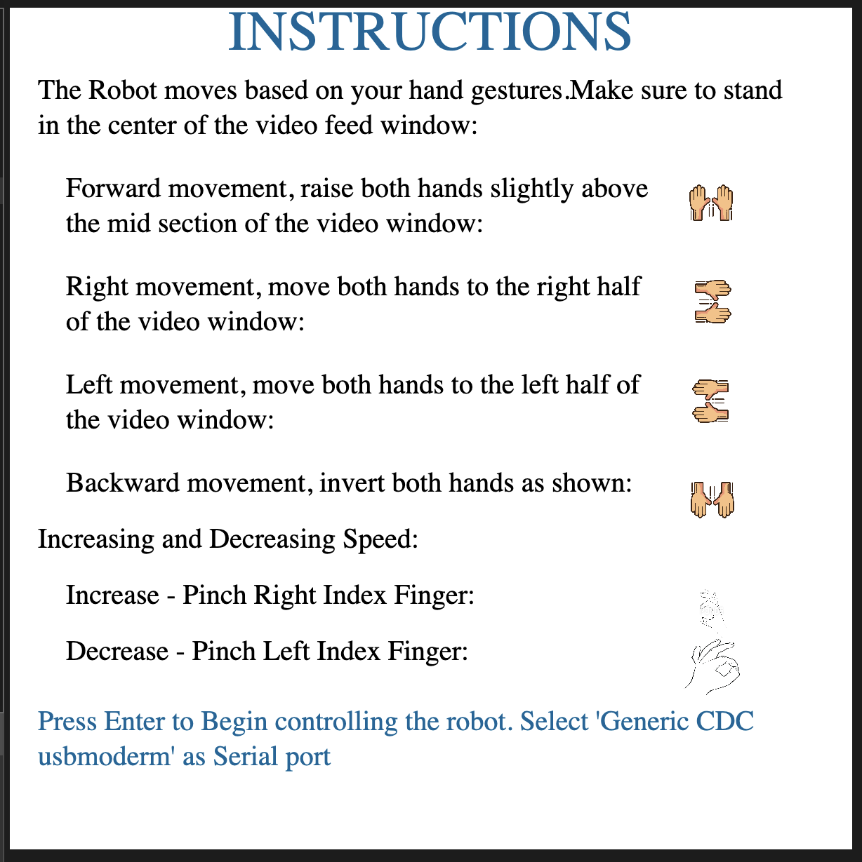
text("The Robot moves based on your hand gestures.Make sure to stand in the center of the video feed window: ", 20, 50, 550, 50);
text("Forward movement, raise both hands slightly above the mid section of the video window: ", 40, 120, 420, 50);
text("Right movement, move both hands to the right half of the video window: ",40, 190, 420, 50);
text("Left movement, move both hands to the left half of the video window: ", 40, 260, 420, 50);
text("Backward movement, invert both hands as shown: ", 40, 330, 420, 50);
//speed
text("Increasing and Decreasing Speed: ", 20, 370, 420, 50);
text("Increase - Pinch Right Index Finger: ", 40, 410, 420, 50);
text("Decrease - Pinch Left Index Finger: ", 40, 450, 420, 50);
fill(0, 102, 153);
text("Press Enter to Begin controlling the robot. Select 'Generic CDC usbmoderm' as Serial port ", 20, 500, 550, 50);
//instruction images
image(forward, 480, 120, 40, 40);
image(right, 480, 190, 40, 40);
image(back, 480, 330, 40, 40);
image(left, 480, 260, 40, 40);
image(pinch_r, 480, 410, 40, 40);
image(pinch_l, 480, 450, 40, 40);
instruct_state = false;
}
}
function command(){
if(command_state == true){
createCanvas(windowWidth, 200);
if(serialActive){
background(255);
textSize(30);
fill(0, 102, 153);
textAlign(CENTER)
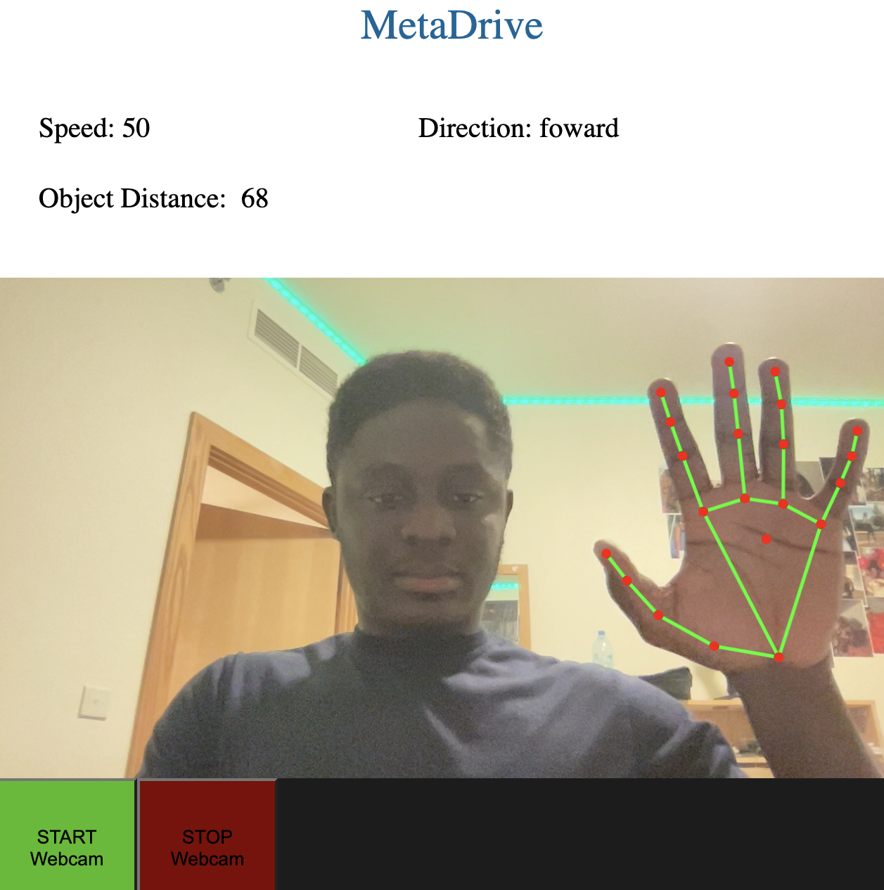
text("MetaDrive", windowWidth/2, 30);
textSize(20);
fill(0);
textAlign(LEFT);
text("Speed: "+ speed, 30, 100);
text("Direction: "+ direct, 300, 100);
if(distance < 10){
fill(255, 0, 0);
}
text("Object Distance: "+ distance, 30, 150);
fingerPosition()
if(once == false){
sethandsfree()
once = true;
}
}
}
}
function mousePressed(){
if(start_state == true){
start_state = false;
instruct_state = true;
}
}
The p5js code has three pages: the start page, instruction page and command page. The three pages move in order based on the events that the user executes. The command page is where the interaction happens between p5js and arduino.
The start page:
The instruction page:
The control page:
Communication between p5js and arduino:
p5js sends 5 integer controls for forward, back, left, right and speed in arduino. Arduino sends the distance measured by the ultrasonic sensor to p5js.
Video Demo:
Project Pictures:
Aspects I’m proud of:
I’m particularly proud of how I drew the hand skeleton, measured the hand gestures and hand positions from the handsfree.js.
function fingerPosition () {
  // Check for pinches and create dots if something is pinched
  const hands = handsfree.data?.hands


  if (hands?.pinchState) {
    // Loop through each hand
    hands.pinchState.forEach((hand, handIndex) => {
      // Loop through each finger
      hand.forEach((state, finger) => {
        if (hands.landmarks?.[handIndex]?.[fingertips[finger]]) {

          // Landmarks are in percentage, so lets scale up
          let x = 640 - hands.landmarks[handIndex][fingertips[finger]].x * 640
          let y = hands.landmarks[handIndex][fingertips[finger]].y * 480

          // Set the position of each finger
          prevPointer[handIndex][finger] = {x, y}
        }
      })
    })
  }

  //pinch right left index finger to decrease volume
  if (hands?.pinchState && hands.pinchState[0][0] === 'released') {
    if(speed > 50){
      speed-=10;
    }
  }

  //pinch right index finger to increase volume
  if (hands?.pinchState && hands.pinchState[1][0] === 'released') {
    if(speed < 200){
      speed +=10;
    }
  }

  //pinch right middle finger to play christmas songs
  if (hands?.pinchState && hands.pinchState[1][1] === 'held') {
    christmas = 1;
  }else{
    christmas = 0;
  }


  let posx_right= int(prevPointer[1][1].x);
  let posy_right = int(prevPointer[1][1].y);

  let posx_left= int(prevPointer[0][1].x);
  let posy_left = int(prevPointer[0][1].y);

  if( (posy_right < 150) && (posy_left < 150) && (posx_right > 320 && posx_left < 320) ){
      direction[0] = 1;
      direct = "foward";
  }
  else{
    direction[0] = 0;
    direct = "";
  }

  if((posy_left >240) && (posy_right > 240) && (posx_right > 320 && posx_left < 320)){
    direction[1] = 1;
    direct = "backward"
  }else{
    direction[1] = 0;
  }

  if((posx_left > 0 && posx_left < 160) && (posx_right > 0 && posx_right < 320)){
    direction[2] = 1;
    direct = "left"
  }
  else{
    direction[2] = 0;
  }

  if(posx_left > 320 && posx_right > 480){
    direction[3] = 1;
    direct = "right"
  }
  else{
    direction[3] = 0;

  }

}
Future Improvements:
I plan to make the communication between arduino and p5js wireless and probably attach a camera to the robot to access the robot arial vision. Another area of improvement is to remodel the robot’s body and 3D print the model.